Sign In
Upload
Manuals
Brands
Ricoh Manuals
Copier
M026
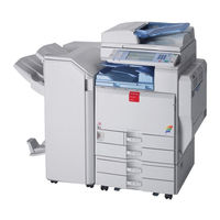
Ricoh M026 Developer Parts Accessories Manuals
Manuals and User Guides for Ricoh M026 Developer Parts Accessories. We have
3
Ricoh M026 Developer Parts Accessories manuals available for free PDF download: Service Manual, Product Support Manual
Ricoh M026 Service Manual (1989 pages)
Brand:
Ricoh
| Category:
Printer
| Size: 80 MB
Table of Contents
Table of Contents
13
Product Information
29
Product Information
35
Specifications
37
Product Overview
38
Component Layout
38
Paper Path
39
Drive Layout
40
Machine Configuration
42
Guidance for those Who Are Familiar with Predecessor Products
46
Installation
47
Installation Requirements
49
Environment
49
Machine Level
50
Machine Space Requirements
50
Machine Dimensions
51
Power Requirements
51
Machine Options
52
Optional Unit Combinations
52
Controller Options
54
Other Options
55
Fax Options
55
Copier Installation
56
Power Sockets for Peripherals
56
Installation Flow Chart
57
Installation Procedure
58
Tapes and Retainers
58
Developer and Toner Bottles
59
Paper Trays
60
Emblem and Decals
61
Initialize the Developer
61
Settings Relevant to the Service Contract
62
SP Operation Sound On/Off Setting
63
Settings for @Remote Service
63
VM Card Installation
68
Enabling App2Me
68
Moving the Machine
69
Transporting the Machine
69
Paper Feed Unit Pb3080 (D387)
70
Accessory Check
70
Installation Procedure
71
Caster Table Type a (D446)
73
Component Check
73
Installation Procedure
74
Accessory Check
75
Paper Feed Unit Pb3010 (D537)
75
Installation Procedure
76
Envelope Feeder Ef3000 (D547)
78
Accessory Check
78
Installation Procedure
79
Lcit Rt3010 (D539)
80
Component Check
80
Installation Procedure
81
Side Fence Position Change
83
Accessory Check
84
Lcit Pb3110 (D538)
84
Installation Procedure
85
Ardf Df3050 (D541)
87
Component Check
87
Installation Procedure
88
Adf Handle Type B (D366)
91
Component Check
91
Installation Procedure
93
Preparing before Installing the DF Handle
93
Installing the DF Handle
94
Component Check
98
Internal Shift Tray Sh3040 (D388)
101
Component Check
101
Installation Procedure
101
Installation Procedure
104
Bridge Unit Bu3030 (D386)
107
Component Check
107
Installation Procedure
108
Finisher Sr3050 (D372)
111
Accessory Check
111
Installation Procedure
112
Sr790 (B408)
114
Accessory Check
114
Nstallation Procedure
115
Booklet Finisher Sr3000 (B793)
117
Accessory Check
117
Installation Procedure
118
Punch Kit Pu3000 (B807)
122
Component Check
122
Installation
123
Key Counter Bracket Type H (A674)
128
Installation Procedure
128
Optional Counter Interface Unit Type a (B870)
130
Installation Procedure
130
Usb2.0/Sd Slot Type F (D546)
132
Accessory Check
132
Installation Procedure
133
Testing the Sd Card/Usb Slot
136
Card Reader Bracket Type C5501 (D547)
137
Component Check
137
Installation Procedure
138
Anti-Condensation Heater (Scanner)
139
Installation Procedure
139
Anti-Condensation Heater Type a
141
Component Check
141
Installation Procedure
142
For Installing the Tray Heater in the Main Machine
142
For Installing the Tray Heater in D537
143
For Installing the Tray Heater in D538
145
For Installing the Tray Heater in D387
148
Controller Options
151
Overview
151
I/F Card Slots
151
SD Card Slots
151
Overview
152
Sd Card Appli Move
152
Move Exec
153
Undo Exec
153
Postscript3 Unit Type C5501
154
Ipds Unit Type C5501
156
File Format Converter Type E
157
Ieee 1284 Interface Board Type a
158
Installation Procedure
158
Installation Procedure
159
Ieee 802.11A/G Interface Unit Type J
159
UP Mode Settings for Wireless LAN
161
SP Mode and up Mode Settings for IEEE 802.11 A/G Wireless LAN
162
Bluetooth Interface Unit Type 3245
163
Camera Direct Print Card Type I
164
Browser Unit Type E
165
Installation Procedure
165
Gigabit Ethernet Type B
167
Check All Connections
168
Preventive Maintenance
169
Maintenance Tables
171
Pm Parts Settings
172
Before Removing the Old Pm Parts
172
After Installing the New Pm Parts
173
Preparation before Operation Check
173
Operation Check
173
Replacement and Adjustment
175
Beforehand
177
Special Tools
178
Image Adjustment
179
Scanning
179
Scanner Sub-Scan Magnification
179
Scanner Leading Edge and Side-To-Side Registration
180
Ardf
181
ARDF Side-To-Side, Leading Edge Registration and Trailing Edge
181
Leading Edge
182
Side to Side
182
Adjustment Standard
182
Image Area
182
Registration
182
ARDF Sub-Scan Magnification
182
Paper Registration Standard
183
Adjustment Procedure
183
Erase Margin Adjustment
184
Color Registration
185
Line Position Adjustment
185
Copy Mode
186
Printer Gamma Correction
186
Printer Mode
192
Exterior Covers
193
Front Door
193
Controller Cover
194
Left Cover
194
Rear Cover
195
Right Rear Cover
195
Operation Panel
196
Paper Exit Cover
197
Inner Tray
197
Ozone Filter and Dust Filter
198
Ozone Filters for the Scanner Unit
198
Ozone Filter and Dust Filter for the IH Inverter
199
Scanner Unit
200
Exposure Glass
200
Original Length Sensors
201
Exposure Lamp
202
Reassembling
203
Scanner Motor
204
Sensor Board Unit (Sbu)
205
When Reassembling
205
Exposure Lamp Stabilizer
206
Sio (Scanner In/Out) Board
206
Scanner Hp Sensor
207
Platen Cover Sensor
208
Front Scanner Wire
210
Reinstalling the Front Scanner Wire
211
Rear Scanner Wire
213
Reinstalling the Rear Scanner Wire
214
Touch Panel Position Adjustment
216
Laser Optics
217
Caution Decal Location
217
Ld Safety Switch
218
Error Messages
218
Laser Optics Housing Unit
219
Preparing the New Laser Optics Housing Unit
219
Recovery Procedure for no Replacement Preparation of Laser Optics Housing Unit
220
Before Removing the Old Laser Optics Housing Unit
220
Removing the Old Laser Optics Housing Unit
221
Installing a New Laser Optics Housing Unit
222
After Installing the New Laser Optics Housing Unit
223
Polygon Mirror Motor and Drive Board
225
Airflow Fans
226
Image Creation
227
Pcdu
227
Drum Unit and Development Unit
228
Developer
231
Toner Collection Bottle
232
Second Duct Fan
233
When Reinstalling the Second Duct Fan
234
Third Duct Fan
234
When Reinstalling the Third Duct Fan
234
Toner Pump Unit
235
When You Install the New Toner Pump Unit
238
Toner End Sensor
240
Image Transfer Belt Unit
241
Image Transfer
241
Image Transfer Belt Cleaning Unit
242
Image Transfer Belt
243
When Reinstalling the Image Transfer Belt
246
Paper Transfer
248
Paper Transfer Roller Unit
248
Paper Transfer Unit
249
ID Sensor Board
251
Cleaning for ID Sensors
252
After Installing a New ID Sensor Unit/Board
253
Temperature and Humidity Sensor
253
Drive Unit
254
Gear Unit
255
When Installing the Drive Unit
259
Adjustment after Replacing the Gear Unit
260
Registration Motor
260
Paper Feed Motor
261
Drum/Development Motors for M, C, and y
262
Drum/Development Motor-K
262
Itb Drive Motor
263
Fusing/Paper Exit Motor
263
Image Transfer Belt Contact Motor
264
Duplex Inverter Motor
264
Pressure Roller Contact Motor
266
Duplex/By-Pass Motor
267
Paper Transfer Contact Motor
268
Toner Transport Motor
270
Toner Collection Unit
271
Paper Feed Clutches
272
Development Clutch-Y
274
Development Clutches for M and C
275
Development Clutch-K
276
Fusing
277
Fusing Unit Maintenance Parts
277
Fusing Unit
277
Fusing Entrance Guide Plate
279
Cleaning Requirement
279
Fusing Exit Guide Plate Cleaning Procedure
280
Heating Roller and Heating Roller Bearing
281
When Re-Installing the Heating Roller
285
Fusing Cleaning Felt
286
When Attaching a New Fusing Cleaning Felt
287
Fusing Lamp
288
Pressure Roller and Pressure Roller Bearing
290
When Re-Installing the Pressure Roller
291
Stripper Plates
293
Cleaning Requirement
294
Heating Roller Thermistor
295
Pressure Roller Thermostat
296
Pressure Roller Thermistors
297
Pressure Roller Thermistor: Center
297
Pressure Roller Thermistor: End
298
Fusing Fan
298
When Installing the Fusing Fan
299
Paper Exit Fan
299
When Installing the Paper Exit Fan
299
Ih (Induction Heating) Inverter Fan
300
When Installing the IH Inverter Fan
300
Thermopile
301
When Cleaning the Lens of the Thermopile
302
Pressure Roller Hp Sensor
303
Ih Coil Fan
304
Ih Coil Unit
304
Paper Feed
307
Paper Feed Unit
307
Tray 1 and Tray 2
308
Separation Roller, Feed Roller and Pick-Up Belt Unit
308
Tray Lift Motor
309
Vertical Transport, Paper Overflow, Paper End and Paper Feed Sensor
310
Registration Sensor
311
By-Pass Paper Size Sensor and By-Pass Paper Length Sensor
312
When Reinstalling the By-Pass Paper Size Sensor
313
By-Pass Bottom Tray
314
By-Pass Paper End Sensor
316
By-Pass Pick-Up, Feed and Separation Roller, Torque Limiter
317
By-Pass Feed Clutch
318
Paper Exit Unit
318
Fusing Exit, Paper Overflow, Junction Paper Jam and Paper Exit Sensor
319
Duplex Unit
321
Duplex Door Sensor
323
Duplex Entrance Sensor
324
Duplex Exit Sensor
326
Electrical Components
327
Boards
327
Controller Unit
330
Controller Box Right Cover
331
Controller Box
332
When Opening the Controller Box
332
When Removing the Controller Box
333
Iob (In/Out Board)
335
Bicu
336
When Installing the New BICU
336
PSU Board
337
PSU Bracket
337
Psu
337
Power Relay Switch
338
Itb Power Supply Board
339
High Voltage Supply Board
339
High Voltage Supply Board Bracket
340
Ih Inverter
340
Controller Board
341
When Installing the New Controller Board
342
Hdd Fan
342
When Installing a New HDD Unit
343
Hdd
343
Reinstallation
344
Disposal of HDD Units
344
Nvram Replacement Procedure
345
NVRAM on the BICU
345
Using Dip Switches
347
Controller Board
347
Bicu Board
347
System Maintenance
349
Entering SP Mode
351
Exiting SP Mode
351
Service Program Mode
351
Enabling and Disabling Service Program Mode
351
Sp Tables
351
Types of Sp Modes
352
SP Mode Button Summary
352
Switching between SP Mode and Copy Mode for Test Printing
353
Selecting the Program Number
354
Service Mode Lock/Unlock
355
Exiting Service Mode
355
Remarks
356
Display on the Control Panel Screen
356
Others
357
Main Sp Tables-1
358
Sp1-XXX (Feed)
358
Main Sp Tables-2
391
Sp2-XXX (Drum)
391
D086/D087 Appendices
931
Appendix: Specifications
935
General Specifications
937
Main Frame
937
Printer
941
Scanner
942
North America
943
Paper Feed
943
Supported Paper Sizes
943
Europe/ Asia
946
1000-Sheet Booklet Finisher
948
Paper Exit
948
1000-Sheet Finisher and 500-Sheet Finisher
950
Platen/Ardf Original Size Detection
953
Printer Drivers
955
Software Accessories
955
Scanner and Lan Fax Drivers
956
Utility Software
957
Ardf (D541)
958
Optional Equipment
958
Lct 2000-Sheet (D538)
959
Paper Feed Unit (D537)
959
1000-Sheet Booklet Finisher & Punch Unit (B793)
960
Lct 1200-Sheet (D539)
960
1000-Sheet Finisher (B408)
962
Lower Tray
962
Upper Tray
962
500-Sheet Finisher (D372)
963
500-Sheet Finisher
964
Bridge Unit (D386)
965
1-Bin Tray Unit (D536)
966
Shift Tray (D388)
966
Appendix: Preventive Maintenance Tables
969
Ardf (D541)
972
Two-Tray Paper Feed Unit (D537)
972
1200-Sheet LCT (D539)
973
2000-Sheet LCT (D538)
973
1000-Sheet Booklet Finisher (B793)
974
1000-Sheet Finisher (B408)
974
Bin Tray (D536)
975
Shift Tray (D388)
975
One-Tray Paper Feed Unit (D387)
976
Ardf
977
Mainframe
977
Others Yield Parts
977
Appendix Sp Mode Tables
979
Sp1-XXX (Feed)
981
System Sp1-XXX
981
Sp2-XXX (Drum)
1021
System Sp2-XXX
1021
-Sheet Finisher B408
1420
Main Pcb
1422
Replacement and Adjustment
1422
Stapler Unit
1423
Motors
1424
Shift Motor
1424
Stapler Motor
1424
Lower Transport Motor
1425
Upper Transport Motor and Exit Motor
1425
Motors and Sensors
1426
Preparation
1426
Stack Height Sensor
1427
Stapler Tray Paper Sensor
1427
Lower Tray Lift Motor
1428
Stack Feed-Out Motor
1428
Jam Detection
1429
Troubleshooting
1429
Dip Switch Settings
1430
Service Tables
1430
Detailed Descriptions
1431
General Layout
1431
Electrical Component Layout
1432
Electrical Component Description
1434
Drive Layout
1436
Junction Gates
1437
Sort/Stack Mode
1437
Staple Mode
1437
Upper Tray Mode
1437
Upper Tray
1438
Lower Tray Up/Down Mechanisms
1439
Paper Shift Mechanism
1440
Jogger Unit Paper Positioning Mechanism
1441
Exit Guide Plate
1442
Stapler Mechanism
1443
Stapler Unit Movement Mechanism
1444
Paper Feed-Out Mechanism
1445
Booklet Finisher B793
1449
Covers
1453
Front/Inner/Rear Covers
1453
Replacement and Adjustment
1453
Upper Covers
1455
Main Body
1457
Shift Tray Position Sensor, Upper Limit Switch
1457
Proof Tray Exit / Full Sensor
1458
Finisher Entrance Sensor
1459
Shift Tray Exit Sensor
1460
Staple Tray Paper Sensor
1461
Shift Tray Motor
1462
Entrance Motor
1463
Upper Transport Motor
1464
Lower Transport Motor
1465
Shift Motor
1466
Folder
1467
Staple Folder Unit
1467
Folder Unit
1468
Folder Unit Exit Sensor
1469
Folder Unit Entrance Sensor
1470
Stapler Unit
1471
Main Board
1481
Others
1481
Dip Switches
1482
Component Layout
1483
Detailed Section Descriptions
1483
Mechanical Component Layout
1483
Electrical Component Layout
1485
Bridge Unit Bu3030 (D386)
1519
Bridge Unit Control Board
1523
Replacement and Adjustment
1523
Bridge Unit Drive Motor
1524
Tray Exit Sensor
1525
Relay Sensor
1526
Details
1527
Mechanical Component Layout
1527
Drive Layout
1528
Electrical Component Layout
1529
Electrical Component Description
1530
Junction Gate Mechanism
1531
Fax Option Type C5000 (D393)
1543
Component Check
1549
Fax Unit (D393)
1549
Installation Procedure
1549
Installation Procedure
1551
Fax Unit Options
1557
Handset (B433)
1557
Memory Unit (G578)
1557
G3 Interface Unit (D393)
1563
For Installing the Single G3 Board
1564
Installation Procedure
1564
For Installing the Double G3 Boards
1567
Fcu
1570
Replacement and Adjustment
1570
Error Codes
1571
Troubleshooting
1571
Ifax Troubleshooting
1592
Cannot Send by IP Address/Host Name
1595
Ip-Fax Transmission
1595
Ip-Fax Troubleshooting
1595
Cannot Send Via Voip Gateway
1596
Cannot Send by Alias Fax Number
1597
Cannot Receive by Voip Gateway
1599
Cannot Receive Via IP Address/Host Name
1599
Ip-Fax Reception
1599
Paper Feed Unit Pb3100 (D537)
1729
Exterior Cover
1731
Rear Cover
1731
Replacement and Adjustment
1731
Electrical Components
1732
Lift Motors
1732
Upper and Lower Paper Feed Clutches
1733
Main Board
1734
Paper Feed Motor
1734
Feed
1735
Paper Feed Unit
1735
Pick-Up, Paper Feed and Separation Rollers
1736
Lift, Paper End, and Relay Sensors
1737
Lcit Pb3110 (D538)
1741
Exterior Cover
1743
Left and Right Tray
1743
Replacement and Adjustment
1743
Changing the Tray Size
1744
Electrical Components
1745
End Fence Hp Sensor/Paper End Sensor 2
1745
Paper Height Sensors on Paper Storage Side
1745
Tray Lift Motor
1746
Main Board
1747
Tray Motor
1747
Stack Transport Clutch
1748
Feed
1749
Paper Feed Unit
1749
Pick-Up, Feed and Separation Rollers
1750
Paper Feed, Paper End, Lift and Relay Sensors
1751
Advertisement
Ricoh M026 Service Manual (1152 pages)
Brand:
Ricoh
| Category:
All in One Printer
| Size: 23 MB
Table of Contents
Table of Contents
12
Service Manual
1
Important Safety Notices
3
Responsibilities of the Customer Engineer
3
Before Installation, Maintenance
3
During Maintenance
4
Safety Devices
5
Lithium Batteries
5
After Installation, Servicing
6
Special Safety Instructions for Toner
7
Safety Instructions for this Machine
8
Laser Safety
10
Symbols, Abbreviations and Trademarks
11
Trademarks
11
Table of Contents
12
Product Information
25
Specifications
25
Machine Configuration
26
Overview
27
Component Layout
27
Paper Path
28
Drive Layout
32
Installation
35
Installation Requirements
35
Environment
35
Machine Level
36
Machine Space Requirements
36
Machine Dimensions
37
Power Requirements
37
Optional Unit Combinations
39
Machine Options
39
Controller Options
39
Fax Options
40
Other Options
40
Copier Installation
41
Installation Flow Chart
41
Accessory Check
42
Installation Procedure
43
SP2-XXX (Drum)
48
VM Card Installation
55
Enabling App2Me
56
Security and Encryption Card
57
Moving the Machine
65
Transporting the Machine
65
Paper Feed Unit (M368)
66
Component Check
66
Installation Procedure
66
Paper Feed Unit (M367)
75
Component Check
75
Installation Procedure
75
Side Tray (M369)
83
Component Check
83
Installation Procedure
83
1-Bin Tray Unit (M370)
88
Component Check
88
Installation Procedure
89
Optional Counter Interface Unit (B870)
95
Installation Procedure
95
Copy Data Security Unit (B829)
97
Installation
97
Tray Heater (Mainframe)
99
Installation Procedure
99
Tray Heater (Optional Unit)
100
Component Check
100
Installation Procedure
100
Controller Options
113
Overview
113
SD Card Appli Move
114
Move Exec
115
File Format Converter Type E
117
IEEE 802.11 A/G (Wireless LAN)
118
Browser Unit Type E
122
Gigabit Ethernet
124
IC Card Reader
125
Check All Connections
127
Preventive Maintenance
129
Maintenance Tables
129
PM Parts Settings
130
Before Removing the Old PM Parts
130
After Installing the New PM Parts
131
Preparation before Operation Check
131
Operation Check
131
Replacement and Adjustment
133
Beforehand
133
Special Tools
134
Image Adjustment
135
Scanning
135
Ardf
136
Registration
137
Erase Margin Adjustment
139
Color Registration
139
Printer Gamma Correction
140
Exterior Covers
146
Toner Collection Bottle
146
Front Door
147
Left Cover
148
Rear Lower Cover
149
Rear Cover
149
Dust Filter
150
Exhaust Filter
151
Right Rear Cover
151
Operation Panel
152
Touch Panel Position Adjustment
156
Paper Exit Tray
157
Inner Right Cover
159
Inner Right Lower Cover
162
Right Upper Cover
164
Scanner Unit
165
Exposure Glass
165
ARDF Exposure Glass
167
LED Board
169
Scanner Motor
171
Sensor Board Unit (SBU)
173
Led-Db
174
Scanner HP Sensor
175
Cover Sensor
176
Front Scanner Wire
177
Rear Scanner Wire
183
Laser Optics
186
Caution Decal Location
186
Laser Unit
186
Ventilation Fan
192
Image Creation
194
PCDU (Photo Conductor and Development Unit)
194
PCU and Development Unit
196
Toner Supply Motor
199
Toner Collection Motor
201
Waste Toner Bottle Full Sensor
203
Waste Toner Bottle Set Sensor
204
RFID CPU Board
204
RFID Board
205
Toner Supply Fan
205
Image Transfer
207
ITB (Image Transfer Belt) Unit
207
Image Transfer Belt, ITB Cleaning Unit
209
ITB Contact Motor
215
ITB Contact Sensor
216
ID Sensor Board
218
Paper Transfer
221
PTR (Paper Transfer Roller) Unit
221
PTR Contact Motor
222
PTR Contact Sensor
225
Temperature and Humidity Sensor
226
Drive Unit
228
Gear Unit
228
Drum Motor: CMY
233
Development Motor: CMY
234
ITB Unit/ Drum: K/ Development: K Motor
235
Development Clutch: K
236
Fusing/Paper Exit Motor
236
Motors with Bracket
237
Registration Motor
239
Duplex/ By-Pass Motor
239
Paper Feed Motor
240
Vertical Transport Motor
241
Drum Phase Sensor: CMY
243
Drum Phase Sensor: K
244
Inverter Motor
245
Drive Unit Fan
246
Fusing
247
Fusing Unit Maintenance Parts
247
Fusing Unit
247
Cleaning Unit
248
Oil Supply Roller
249
Cleaning Roller
250
Plain Shaft Bearing
250
Pressure Roller Fusing Lamp
251
Pressure Roller
254
Heating Roller Fusing Lamp
256
Fusing Belt
262
Fusing, Heating and Tension Roller
263
Heating Roller Thermostat
265
Heating Roller Thermistor
265
Pressure Roller Thermistor
266
Pressure Roller Thermostat
267
Thermopile
268
Fusing Front Fan
269
Fusing Rear Fan
270
Paper Feed
272
Separation Roller
272
Paper Feed Unit
272
Pick-Up and Paper Feed Rollers
274
Registration Sensor
275
Vertical Transport Sensor
276
Paper Lift Sensor
277
Paper End Sensor
278
Paper Feed Sensor
279
Tray Lift Motor
280
Paper Size Switch
281
Cleaning the Paper Dust Container
281
Paper Exit
283
Paper Exit Unit
283
Paper Exit Sensor
287
Paper Overflow Sensor
287
Fusing Exit Sensor
288
Duplex Unit
291
By-Pass Tray Unit
292
Duplex Entrance Sensor
294
Duplex Exit Sensor
295
Inverter Sensor
296
Fusing Entrance Sensor
298
By-Pass Paper Size Sensor
298
By-Pass Paper End Sensor
300
By-Pass Pick-Up Roller
300
By-Pass Feed and Separation Rollers
301
Hvps: D
302
Ardf
304
ARDF Rear Cover
306
ARDF Front Cover and Original Tray
306
Original Feed Unit
307
Pick-Up Roller
308
Feed Roller
309
Friction Pad
310
ARDF Drive Board
310
Original Set Sensor and ARDF Top Cover Sensor
311
Feed Motor
313
Feed Clutch
315
Transport Motor
315
Registration Sensor
317
Inverter Sensor
318
Cooling Fan
320
Internal Finisher
322
Output Tray Unit
324
Stapler Unit
325
Gathering Roller Motor
325
Paper Exit Motor
326
Shift Roller Motor
327
Transport Motor
328
Tray Lift Motor
328
Jogger Motor
330
Exit Guide Plate Motor
333
Shift Roller HP Sensor
333
Gathering Roller HP Sensor
334
Jogger Fence HP Sensor
335
Entrance Sensor
337
Paper Exit Sensor
337
Paper Sensor
339
Staple Tray Paper Sensor
339
Tray Lower Limit Sensor
340
Main Board
341
Electrical Components
343
Boards
343
Controller Box Cover
344
Controller Box
345
Controller Board
350
Hdd
351
Controller Fan
353
Bcu
354
NVRAM/EEPROM Replacement Procedure
358
Ipu
359
PSU Box
360
Psu
361
HVPS: T1T2 Board
362
HVPS: CB Board
363
Sdb
364
System Maintenance
367
Service Program Mode
367
SP Tables
367
Enabling and Disabling Service Program Mode
367
Types of SP Modes
367
Selecting the Program Number
368
Exiting Service Mode
369
Remarks
370
Main SP Tables-1
372
SP1-XXX (Feed)
372
Main SP Tables-2
391
SP2-XXX (Drum)
391
Main SP Tables-3
418
SP3-XXX (Process)
418
Main SP Tables-4
449
SP4-XXX (Scanner)
449
Main SP Tables-5
465
SP5-XXX (Mode)
465
Main SP Tables-6
512
SP6-XXX (Peripherals)
512
Main SP Tables-7
514
SP7-XXX (Data Log)
514
Main SP Tables-8
542
SP8-XXX (Data Log2)
542
Main SP Tables-9
587
Input Check Table
587
Output Check Table
593
Printer Service Mode
600
Scanner Service Mode
609
Test Pattern Printing
610
Firmware Update
613
Type of Firmware
613
Before You Begin
614
Updating Firmware
615
Update Procedure for App2Me Provider
617
Browser Unit Update Procedure
619
Handling Firmware Update Errors
620
Installing Another Language
622
Reboot/System Setting Reset
625
Software Reset
625
System Settings and Copy Setting Reset
625
Controller Self-Diagnostics
627
Overview
627
Downloading Stamp Data
629
NVRAM Data Upload/Download
630
Uploading Content of NVRAM to an SD Card
630
Downloading an SD Card to NVRAM
630
Address Book Upload/Download
632
Information List
632
Download
632
Upload
633
Using the Debug Log
634
Overview
634
Switching on and Setting up Save Debug Log
634
Retrieving the Debug Log from the HDD
638
Recording Errors Manually
638
Debug Log Codes
639
Card Save Function
640
Overview
640
Procedure
640
Error Messages
643
Troubleshooting
645
SC Tables
645
Service Call Conditions
645
Sc1Xx: Scanning
648
SC 2Xx: Exposure
652
Sc3Xx: Image Processing - 1
656
Sc3Xx: Image Processing - 2
657
Sc4Xx: Image Processing - 3
660
Sc5Xx: Paper Feed and Fusing
664
Sc6Xx: Device Communication
675
Sc7Xx: Peripherals
685
Sc8Xx: Overall System
689
Sc9Xx: Miscellaneous
701
Process Control Error Conditions
706
Developer Initialization Result
706
Process Control Self-Check Result
707
Line Position Adjustment Result
709
Troubleshooting Guide
711
Line Position Adjustment
711
Problem at Regular Intervals
717
Blank Print
719
All-Black Print
719
Missing CMY Color
720
Light Print
720
Repeated Spots or Lines on Prints
720
Dark Vertical Line on Prints
721
White Horizontal Lines or Bands
722
Missing Parts of Images
722
Dirty Background
722
Partial CMY Color Dots
723
Dark Irregular Streaks on Prints
723
CMY Color Irregular Streaks
723
Ghosting
723
Unfused or Partially Fused Prints
724
Image Skew
724
Background Stain
725
No Printing on Paper Edge
725
Image Not Centered When It Should be
725
Jam Detection
726
Paper Jam Display
726
Jam Codes and Display Codes
726
Electrical Component Defects
731
Sensors
731
Blown Fuse Conditions
736
Scanner Test Mode
737
SBU Test Mode
737
Energy Saving
739
Energy Save
739
Energy Saver Modes
739
Energy Save Effectiveness
740
Paper Save
743
Effectiveness of Duplex/Combine Function
743
Ricoh M026 Product Support Manual (54 pages)
Color MFP
Brand:
Ricoh
| Category:
Copier
| Size: 1 MB
Table of Contents
Main Frame
2
Installation Requirements
7
Power Requirements
7
Copy Specifications
18
Printer Specifications
19
Fax Specifications
25
Document Server
30
Utility Software
46
Special Paper
50
Contact Information
52
Advertisement
Advertisement
Related Products
Ricoh M022
Ricoh M024
Ricoh M028
Ricoh M075
Ricoh Aficio MP C3502
Ricoh MP 2014 Series
Ricoh MP C3004 series
Ricoh MP 1813L
Ricoh MPC 2050
Ricoh M020
Ricoh Categories
All in One Printer
Printer
Digital Camera
Copier
Printer Accessories
More Ricoh Manuals
Login
Sign In
OR
Sign in with Facebook
Sign in with Google
Upload manual
Upload from disk
Upload from URL