Sign In
Upload
Manuals
Brands
Perkins Manuals
Engine
UA
Perkins UA Manuals
Manuals and User Guides for Perkins UA. We have
2
Perkins UA manuals available for free PDF download: Workshop Manual, Manual
Perkins UA Workshop Manual (206 pages)
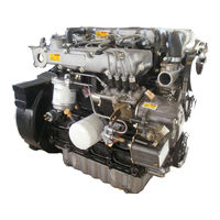
four cylinder naturally aspirated and turbocharged diesel engines
Brand:
Perkins
| Category:
Engine
| Size: 30.66 MB
Table of Contents
Table of Contents
3
1 General Information
13
Introduction
13
Engine Views - Naturally Aspirated Engine
15
Engine Views - Turbocharged Engine
16
Engine I.D. Location
17
Specifications
17
Safety Precautions
18
Viton Seals
20
Engine Lift Equipment
21
POWERPART Consumable Products
22
2 Specifications
25
Basic Engine Data
25
Data and Dimensions
26
Timing Case and Drive Assembly
35
Lubrication System
39
Fuel System
40
Thread Sealant
42
Recommended Torque Tensions
43
Cooling System
44
Compression Test Data
45
3 Cylinder Head Assembly
47
Rocker Cover
47
Rocker Assembly (Latest Engines)
48
Rocker Assembly (Earlier Engines)
50
Rocker Shaft (Latest Engines)
52
Rocker Shaft (Earlier Engines)
53
Valve Tip Clearance
54
Valve Springs (with Cylinder Head Fitted)
55
Special Tools
55
Exhaust / Induction Manifolds and Gasket
56
Cylinder Head Setscrews
57
Cylinder Head Gasket
58
Valve and Valve Springs
59
Valve Stem
60
Valve Depth
61
Valve Guides
62
Valve Seats
64
Valve Seat Insert
65
Cylinder Head
65
Cylinder Head
66
4 Piston and Connecting Rod Assemblies
67
Big End Bearing and Cap
67
Piston and Connecting Rod
70
Piston and Piston Rings
76
Piston Rings
78
Connecting Rod
79
Small End Bush
84
Piston Height above the Cylinder Block
85
Piston Cooling Jets (UC Engines)
86
5 Crankshaft Assembly
89
Crankshaft Pulley
89
Rear Oil Seal
92
Thrust Washers and Crankshaft End-Float
94
Thrust Washers
95
Main Bearing Caps (with Crankshaft in Position)
96
Main Bearings
97
Main Bearing Caps (Front and Rear)
98
Crankshaft
100
Wear Sleeve
104
6 Timing Case and Drive Assembly
107
Tamper Proof Screws
107
Timing Case
109
Gear Teeth Meshing
112
Front Oil Seal
113
Idler Gear
114
Idler Gear Bushes
115
Idler Gear Hub
116
Camshaft Assembly for the Fuel Injection Pump
117
Camshaft Assembly and Tappets for the Valves
118
Camshaft Assembly for the Valves
119
Crankshaft Gear
120
7 Cylinder Block Assembly
123
Cylinder Block Bores
123
Camshaft Bores
124
8 Engine Timing
127
To Set Approximately Number 1 Piston to TDC on the Compression Stroke
127
Valve Timing
129
Fuel Injection Pump Timing
130
9 Aspiration System
135
Turbocharger
135
10 Lubrication System
143
Oil Filter Canister
143
Engine Lubricating Oil
144
Filter Head and Oil Cooler
145
Aluminium Sump
146
Steel Sump
147
Oil Strainer and Suction Pipe
148
Lubricating Oil Pump
149
Relief Valve
151
11 Fuel System
153
Fuel Filter Element
153
Atomiser Fault
155
High Pressure Fuel Pipes
156
Leak off Rail
157
To Change a Plain Bush to a Threaded Bush
167
To Record the Maximum Fuel Position of the Fuel Control Rack
171
How to Use the Reference Setting for Maximum Fuel
176
Thermostat
179
Flywheel and Housing
185
Starter Ring
187
Flywheel Housing
188
Alternator
189
Drive Belt
189
Electrical Equipment
189
Glowplugs (Starting Aid)
191
Operation 14-4 to Check
194
Starter Motor
196
Electrical Stop Solenoid
197
Auxiliary Equipment
199
Power Take-Off Assembly
199
Special Tools List
201
Advertisement
Perkins UA Manual (159 pages)
700 series 4 cylinder naturally aspirated and turbocharged diesel engines
Brand:
Perkins
| Category:
Engine
| Size: 6.37 MB
Table of Contents
How to Use this Manual
2
Contents
6
General Safety Precautions
10
Engine Lift Equipment
11
Viton Seals
12
Consumable Products
13
Engine Identification - Location
15
Engine Views
16
Compression Test Data
18
How to Do a Compression Test
18
Specifications
19
Recommended Torque Tensions
20
Data and Dimensions
22
Cylinder Head Assembly Data
25
Crankshaft Data
29
Timing Case and Drive Assembly
30
Lubrication Oil Pump Data
31
Pistons Data
32
Big-End Bearings Data
33
Gudgeon Pins Data
33
Fuel Injection Pump Data
34
Electrical Equipment Data
35
Auxiliary Equipment
35
Cylinder Head Assembly
36
Rocker Cover - to Remove and to Fit
36
Rocker Assembly - to Remove and to Fit
37
Rocker Shaft - to Dismantle, to Inspect and to Assemble
39
Valve Tip Clearance - to Check
41
Valve Springs (with Cylinder Head Fitted) - to Remove and to Fit
42
Exhaust/Induction Manifolds and Gaskets - to Remove and to Fit
43
Cylinder Head Setscrews - to Remove and to Fit
44
Cylinder Head Gasket - to Remove and to Fit
45
Valve and Valve Springs - to Remove and to Fit
46
Valve Stem - to Inspect
47
Valve Depth - to Check
48
Valve Guides - to Check
49
Valve Guides - to Remove and to Fit
50
Valve Seats - to Correct
51
Valve Seat Insert - to Fit
52
Piston and Connecting Rod Assembly
53
Big and Bearing and Cap - to Remove and to Fit
53
Notes on Connecting Rods
53
Cylinder Head - to Check the Distortion of the Lower Face
54
Piston and Connecting Rod - to Dismantle and Assemble
55
Piston and Piston Ring - Inspection
56
Piston and Connecting Rod - to Fit
59
Connecting Rod - to Check for Bend and to Inspect
60
Connecting Rod - to Check the Length and to Inspect
61
Small End Bush - to Remove and to Fit
62
To Check the Piston Height above the Cylinder Block
63
Connecting Rod Assembly
64
Piston Cooling Jets (UC Engines) - to Remove, to Fit and to Align
64
Crankshaft Pulley - to Remove and to Fit
65
Crankshaft Pulley - to Fit a Wear Sleeve
66
Rear Oil Seal - to Remove
67
Rear Oil Seal - to Fit
68
Thrust Washers and Crankshaft End-Float - to Inspect
69
Thrust Washers - to Remove and to Fit
70
Main Bearing Caps (with Crankshaft in Position) - to Remove and to Fit
71
Main Bearings - to Inspect
72
Main Bearing Caps (Front and Rear) - to Remove
73
Main Bearing Caps (Front and Rear) - to Fit
74
Crankshaft - to Remove
75
Crankshaft - to Fit
76
Crankshaft - to Inspect and to Overhaul
77
Wearsleeve - to Fit
78
Timing Case - to Remove and to Fit
79
Tamper Proof Screws
80
Timing Case - to Fit
82
Timing Case - to Renew
83
Front Oil Seal - to Remove and to Fit
84
Idler Gear - to Remove
85
Idler Gear Bushes - to Remove and to Fit
86
Idler Gear Hub - to Remove and to Fit
87
Camshaft Assembly for the Fuel Injection Pump - to Remove and to Fit
88
Camshaft Assembly and Tappets for the Valves - to Remove and to Fit
89
Camshaft Assembly for the Valves - to Remove and to Fit
90
Backplate - to Remove and to Fit
91
Crankshaft Gear - to Remove and to Fit
92
Cylinder Block Assembly
93
Cylinder Block Bores - to Inspect
93
Camshaft Bush - to Renew
94
Engine Timing
95
To Set Approximately Number 1 Piston to TDC on the Compression Stroke
95
Fuel Injection Pump Timing
97
To Check Valve Timing
98
Turbocharger - to Remove and to Fill
101
To Clean the Impeller and Compressor Casing
103
Engine Breather Assembly - to Renew
104
Lubrication System
105
Oil Filter Canister - to Renew
105
Engine Lubricating Oil - to Renew
106
Filter Head and Oil Cooler - to Remove and Fit
107
Sump - to Remove and to Fit
108
Oil Strainer and Suction Pipe - to Remove and Fit
109
Lubricating Oil Pump - to Renew
110
Lubricating Oil Pump - to Inspect
111
Relief Valve - to Remove, to Fit and to Renew
112
Fuel System
113
Fuel Filter Element - to Renew
113
Atomiser Fault - to Inspect
114
High Pressure Fuel Pipes - to Remove and to Fit
115
Leak off Rail - to Remove and to Fit
116
Atomisers - to Remove and to Fit
117
Fuel Lift Pump - to Remove and to Fit
118
Fuel Lift Pump - to Test
119
Fuel Injection Pump - to Remove and to Fit
120
To Eliminate Air from Fuel System
122
Governor Weight Assembly - to Remove and to Fit
123
Speed Control Lever Assembly - to Remove and to Fit
124
Speed Control Lever Assembly - to Renew
125
To Change a Plain Bush to a Threaded Bush
126
Fuel Injection Pump Linkage - to Remove and to Fit
127
Fuel Injection Pump Linkage - to Renew
128
To Record the Maximum Fuel Position of the Fuel Control Rack
129
How to Use the Reference Setting for Maximum Fuel
134
Cooling System
136
To Drain and Fill the Cooling System
136
Thermostat - to Remove and to Fit
137
Thermostat - to Test
138
Fan - to Remove and to Fit
139
Coolant Pump - to Remove and to Fit
140
Oil Cooler - to Remove and to Fit
141
Flywheel and Flywheel Housing
142
Flywheel - to Remove and to Fit
142
Flywheel - to Inspect
143
Starter Ring - to Remove and to Fit
144
Flywheel Housing - to Remove and to Fit
145
Electrical Equipment
146
Drive Belt - to Remove and to Fit
146
Alternator - to Remove and to Fit
147
Glowplugs (Starting Aid) - to Remove and to Fit
148
Glowplugs (Starting Aid) - to Check
149
Starter Motor - to Remove, to Fit and to Test
150
Electrical Stop Solenoid - to Remove and to Fit
151
Power Take-Off Assembly - to Remove and to Fit
152
Power Take-Off Assembly - to Dismantle and to Assemble
153
Special Equipment
154
List of Special Tools
154
Advertisement
Related Products
Perkins UB
Perkins UC
Perkins 100 Series
Perkins 1000 Series
Perkins 102-05
Perkins 103-06
Perkins 103-07
Perkins 103-09
Perkins 103-10
Perkins 103-13
Perkins Categories
Engine
Lifting Systems
Compact Loader
Inverter
Speakers
More Perkins Manuals
Login
Sign In
OR
Sign in with Facebook
Sign in with Google
Upload manual
Upload from disk
Upload from URL