Sign In
Upload
Manuals
Brands
Opticon Manuals
Laboratory Equipment
NLV-5201
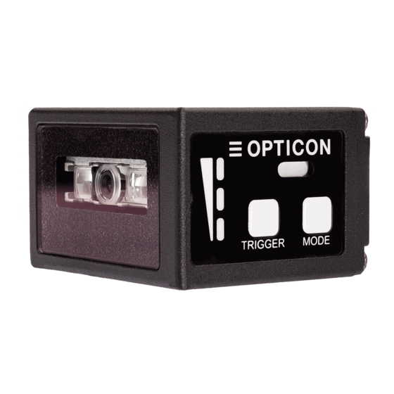
Opticon NLV-5201 Fixed Position Scanner Manuals
Manuals and User Guides for Opticon NLV-5201 Fixed Position Scanner. We have
3
Opticon NLV-5201 Fixed Position Scanner manuals available for free PDF download: User Manual, Specification Manual
Opticon NLV-5201 User Manual (172 pages)
Fixed Position 2D Imager Scanner
Brand:
Opticon
| Category:
Laboratory Equipment
| Size: 7 MB
Table of Contents
Caution and Warning
3
Table of Contents
6
1 Abstract
11
Features of the Scanner
12
Usage of the Scanner
13
Flow to Integrate
14
Flow to Integrate for Industrial Uses
14
Flow to Integrate for General Uses
15
2 Before Using
16
Model Details
17
Standard
17
Model Description
17
Package Contents
18
Connect to the Host
19
How to Read
21
Depth of Field and Focus Type
22
Standard Model (SR) Depth of Field
22
High Resolution Model (HD) Depth of Field
23
Ultra High Resolution Model (UD) Depth of Field
24
Detailed View
25
Operation Mode and Control Panel Description
26
Operation Mode
26
Control Panel Operation Specifications
27
LED Indicator Specifications
28
Buzzer and LED Indicator
29
Operation Transition
30
Normal Trigger
30
Auto Trigger
31
Operation Invalid Transition Diagram
32
Installation of the Scanner
33
Scan Area
34
Image Range
34
Optical Path
35
Scanned Media and Placement
36
Solution for Specular Reflection of the LED Illumination
36
Solution for Specular Reflection of the External Illumination
37
Exit Window Placement
38
Exit Window Material
38
Solution for Specular Reflection of the Illumination
39
3 Configurations
40
Configuring with Commands
41
Command Packet
41
Configuring with 2D Menu
42
Configuring with 1D Menu Code
43
Command Packet Sending Precautions
44
Each Interface Default Setting
44
Save Settings
45
Custom Setting
45
Basic Commands
46
ACK/NAK for Serial Commands
46
Diagnostic Commands
46
Enable/Disable 2D Menu Code
46
Enable/Disable 1D Menu Code
46
Image Settings
47
Buzzer and Indicator
48
Disable Reading Operation
48
Enable/Disable Mode Key
48
Reboot the Scanner
48
Direct Numerical Input Command
49
4 Indicator Options
50
Buzzer
51
Buzzer Loudness
51
Good Read Buzzer
51
Start-Up Buzzer
52
Read Timeout Buzzer
52
Intermediate Buzzer
52
Status LED
53
Status LED Lighting Time
53
Good Read Aiming
54
Indicator in General
55
Indicator Timing
55
5 Interface
56
Rs-232C
57
RS-232C Basic Information
58
Baud Rate (Transfer Speed)
58
Character Format
59
Handshaking (Flow Control)
59
Inter Character Delay (RS-232C)
64
Trouble Shooting (RS-232C)
64
Usb-Hid
65
USB-HID Basic Information
66
Connection Confirmation (USB-HID)
67
Numlock Capslock Control
67
Data Output Speed (USB-HID)
68
Inter Character Delay (USB-HID)
68
Keyboard Language
69
Trouble Shooting (USB-HID)
70
Usb-Com
71
USB-COM Basic Information
72
Integration (USB Driver)
72
Connection Confirm
72
Fixed USB-COM Port
73
COM to HID Output
73
Connection Method
73
Trouble Shooting (USB-COM)
74
Common Settings
75
Data Buffer Mode
75
6 Reading and Timing
76
Reading and Trigger Control
77
Code Read Timing
77
Command Trigger Control
78
External Trigger Signal Control
79
Read Time Setting
80
Trigger Delay
81
Decode Timeout
82
OK/NG Signal
83
Enable/Disable OK/NG Signal
83
OK/NG Signal Behavior Settings
84
7 Tuning and Bank Function
85
Tuning Overview
86
Tuning Function
86
Tuning Setting Flow
87
Tuning
88
Execute Tuning
88
Setting the Exposure Adjustment Range of Tuning
89
Reading Test
90
Reading Test Command
90
Bank Function
91
Bank Selection
91
Bank Specify Trigger
91
Confirm Current Bank
91
Initialize Bank
91
8 Read Options
92
Read Modes Overview
93
Read Operation Flow
93
Read Modes
94
Batch Reading
96
Data Edit Function
96
Auto Trigger
97
Auto Trigger Sensitivity
97
Double Read Reset Time
97
Normal Auto Trigger (Without Stand)
97
Auto Trigger Sleep Mode
98
Read Time Adjustment
98
Illumination and Aiming
99
Reading LED Illumination
99
LED Aiming
99
9 Code Options
100
Setting of Readable Codes
101
Codes
101
Postal Code
102
GS1 Databar
103
GS1 Composite Code
103
Codes
104
Other Options for Codes
104
Ocr
105
Setting of Code Common Options
106
GS1 Convert
106
Positive and Negative Image of Barcodes (1D Code Common)
107
Redundancy (1D Code Common)
108
Add-On Waiting Time
108
ECI Protocol Output
109
OCR Free Edit
110
Setting of Code Specific Options
111
Upc
111
Ean/Jan
114
Code 39 and It. Pharm (Code 32)
118
Codabar
120
Interleaved 2 of 5 and S-Code
122
Code128
123
Iata
124
Msi/Plessey
124
Telepen
124
Uk/Plessey
124
Code 11
125
Korean Postal Authority
125
GS1 Databar
126
Composite GS1 Databar
127
Pdf 417
128
QR Code
129
Data Matrix
131
Aztec Code
132
Setting of Number of Characters
133
Fixed Length ON, Minimum / Maximum Length for Selected Codes
133
Command List: Fixed Length On/Minimum/Maximum Length
134
10 String Options
135
Prefix / Suffix (Appending Character Function)
136
Program Value
137
Set Prefix / Suffix
138
Command List: Settings of the Prefix / Suffix
139
ASCII (Prefix / Suffix Values)
141
Code ID
142
Code Length
142
Code Coordinates
143
Scan Time
144
Case Conversion
145
11 Appendix
146
Code ID Table
147
Opticon Code ID Prefix / Suffix Value
147
Code Option AIM / ISO15424 Code ID Prefix / Suffix Value
148
NLV-5201 Specification Overview
152
Common Specification Overview
152
Technical Specifications
155
Detailed View
158
Product Label
159
Sample Codes
160
Barcode
160
Postal Code
164
GS1 Databar
165
GS1 Composite Code
166
Code
168
OCR Font (Machine Readable Travel Document)
169
OCR Font (Free OCR Edit)
170
Advertisement
Opticon NLV-5201 Specification Manual (54 pages)
Fixed Mount 2D Imager Scanner
Brand:
Opticon
| Category:
Scanner
| Size: 4 MB
Table of Contents
Table of Contents
5
1 Overview
9
2 About the NLV-5201 2D Imager Scanner
9
Model Details
9
Standard Product Description
10
3 Physical Features
10
4 Detailed View
11
Figure 1: Detailed View of NLV-5201
11
5 Basic Operation Mode
12
Exposure Control
13
Automatic Adjustment Exposure Control
13
Tuning Exposure Control
13
Figure 2: Automatic Adjustment Exposure Control
13
Figure 3: Tuning Exposure Control
13
Operation Modes and Status
14
Control Panel Operation Specifications
15
LED Indicator Specifications
16
6 Electrical Specifications
17
7 Power Specifications
17
Figure 4: Electrical Configuration Diagram
17
8 Interface Specification
18
RS-232C Interface
18
Initial RS-232C Communication Settings
18
Interface Signals
18
Signal Level
19
RS-232C Interface Circuit
19
Figure 5: Interface Circuit (RS-232C)
19
RS-232C Interface Cable
20
USB Interface
20
Figure 6: RS-232C Loose End Interface Cable
20
Figure 7: USB Plug (A) Pin Assignment
21
Figure 8: Interface Circuit (USB)
21
USB Connector
21
USB Interface Circuit
21
USB Interface Specifications
21
USB Interface Cable
22
9 Optical Specifications
22
Basic Optical Specifications
22
Figure 9: USB Interface Cable
22
Aiming Pattern
23
Image Range
23
Figure 10: Aiming Pattern and Image Range
23
10 Technical Specifications
24
Figure 11: Test Condition for Depth of Field
24
Barcode Test Labels
25
GS1 Databar/Composite
25
Scan Area and Depth of Field
26
Figure 12: Scan Area and Depth of Field
28
Printed Contrast Signal (PCS)
31
Minimum Resolution
32
Barcode Width
33
Figure 13: Barcode Width
33
Pitch, Skew and Tilt
34
Figure 14: Pitch, Skew, and Tilt
34
Curvature
35
Figure 15: Curvature
35
Motion Tolerance
36
Figure 16: Motion Tolerance
36
Scan Speed
37
Figure 17: Scan Speed
37
Auto Trigger
38
Figure 18: Auto Trigger
38
Indicator Specifications
39
Imager Specifications
39
11 Environmental Specifications
39
Temperature
39
Humidity
39
Ambient Light Immunity
40
Environmental Durability (IP)
40
Key Durability
40
Figure 19: Ambient Light Immunity
40
Figure 20: Key Durability
40
Cable Strength
41
Cable Bending Strength
41
Vibration Resistance
41
Vibration Resistance of the Imager Scanner
41
Vibration Resistance of the Imager Scanner in Packaging
41
Figure 21: Cable Bending Strength
41
Drop Impact Resistance
42
Drop Impact Resistance of the Imager Scanner
42
Drop Impact Resistance of the Imager Scanner in Packaging
42
Electrostatic Discharge Immunity
42
Figure 22: Drop Impact Strength
42
Radio Frequency Electromagnetic Field Amplitude Modulation
43
Power Frequency Magnetic Field
43
12 Regulatory Compliance
43
LED Safety
43
Emc
43
13 Rohs
44
14 Reliability
44
15 Precautions
44
16 Cleaning NLV-5201
45
Figure 23: Cleaning NLV-5201
45
17 Product Labels
46
Serial Number Label
46
Address Label
46
Figure 24: Serial Number Label
46
Figure 25: Serial Number Label Affixed to the NLV-5201
46
Figure 26: Address Label
46
Figure 27: Address Label Affixed to the NLV-5201
46
18 Packaging Specifications
47
Individual Packaging Specification
47
Figure 28: Individual Packaging (USB)
47
Collective Packaging Specification
48
Figure 29: Collective Packaging
48
19 Mechanical Drawing
49
Figure 30: Mechanical Drawing
49
20 Default Factory Settings
50
Barcode Default Settings
50
Postal Code Default Settings
51
GS1 Databar Default Settings
51
Composite GS1 Default Settings
52
Barcode Default Settings
53
OCR Font Default Settings
53
Read, Trigger, and Buzzer Default Settings
54
Interface Communication Default Settings
54
RS-232C Default Settings
54
USB Default Settings
54
Opticon NLV-5201 Specification Manual (47 pages)
Fixed Position 2D Imager Scanner, Standard range
Brand:
Opticon
| Category:
Laboratory Equipment
| Size: 3 MB
Table of Contents
Table of Contents
4
1 Abstract
7
2 Overview
7
3 Model Details
8
Standard
8
Model Description
8
4 Basic Specifications
9
5 Detailed View
12
Figure 1: Detailed View of NLV-5201
12
6 Basic Operation Mode
13
Exposure Control Method
13
Operation Modes and Status
13
Figure 2: Exposure Control Method
13
Control Panel Operation Specifications
14
LED Indicator Specifications
15
7 Electrical Specifications
16
Electrical Characteristics
16
Figure 3: Configuration Diagram
16
8 Optical Specifications
17
Basic Optical Specifications
17
Aiming Pattern
18
Figure 4: Aiming Pattern and Imaging Range
18
Image Range
18
Figure 5: Reading Condition
19
Barcode Test Sample
20
Figure 6: Scan Area and Resolution
21
Scan Area
21
Depth of Field
22
Barcode Width
23
Figure 7: Barcode Width
23
Minimum Resolution
23
Printed Contrast Signal (PCS)
23
Curvature
24
Figure 8: Pitch, Skew and Tilt
24
Figure 9: Curvature
24
Pitch, Skew and Tilt
24
Figure 10: Barcode Moving Vertically
25
Motion Tolerance
25
Figure 11: Scan Speed
26
Scan Speed
26
Auto Trigger
27
Figure 12: Auto Trigger
27
9 Technical Specifications
19
10 Interface Specification
28
RS-232C Interface
28
Initial Communication Settings
28
Pin Assignment
28
Signal Level
28
RS-232C Interface Circuit
29
RS-232C Interface Cable
29
Figure 13: Interface Circuit (RS-232C)
29
Figure 14: RS-232C Loose End Interface Cable
29
USB Interface
30
USB Interface Specifications
30
Figure 15: USB Plug (A) Pin Assignment
31
Figure 16: Interface Circuit (USB)
31
Figure 17: USB Interface Cable
31
USB Connector
31
USB Interface Cable
31
USB Interface Circuit
31
11 Environmental Specifications
32
Temperature
32
Humidity
32
Ambient Light Immunity
33
Dust and Drip Proof
33
Figure 18: Ambient Light Immunity
33
Cable Bending Strength
34
Cable Strength
34
Figure 19: Key Durability
34
Figure 20: Cable Bending Strength
34
Key Durability
34
Drop Impact Strength (in Individual Packaging)
35
Drop Impact Strength (Without Packaging)
35
Electrical Specifications
35
Figure 21: Drop Impact Strength
35
Vibration Strength (in Individual Packing)
35
Vibration Strength (Without Packing)
35
12 Regulatory Compliance
36
LED Safety
36
Emc
36
13 Rohs
36
14 Reliability
36
15 Precautions
37
Caution and Warning
37
Cleaning NLV-5201
38
Figure 22: Cleaning NLV-5201
38
16 Product Display
39
Product Label
39
Address Label
39
Figure 23: Product Label
39
Figure 24: Address Label
39
17 Packaging Specifications
40
Individual Packaging Specification
40
Figure 25: Individual Packaging (USB)
40
Collective Packaging Specification
41
Figure 26: Collective Packaging
41
18 Physical Features
42
Dimensions
42
Weight
42
Mechanical Drawing
42
Figure 27: Mechanical Drawing
42
19 Factory Setting
43
Default Setting (Part 1: Readable Codes)
43
Barcodes
43
Postal Code
43
Composite GS1
44
GS1 Databar, Composite Code
44
Codes
45
OCR Font
45
Default Setting (Part 2: Read Setting, Trigger, Buzzer)
46
Default Setting (Part 3: Interface Communication Setting)
47
Rs-232C
47
Usb
47
Advertisement
Advertisement
Related Products
Opticon NLV-3101-HD
Opticon NLV 2001
Opticon NLV-4001
Opticon NFT 1125 Series
Opticon NFT 2135 Series
Opticon NFT 2100
Opticon NLB 9625
Opticon NLB 9645
Opticon NFT 2200
Opticon NLB-1000
Opticon Categories
Barcode Reader
Scanner
Handhelds
Touch terminals
Telescope
More Opticon Manuals
Login
Sign In
OR
Sign in with Facebook
Sign in with Google
Upload manual
Upload from disk
Upload from URL