Table of Contents
Advertisement
Quick Links
Advertisement
Table of Contents

Subscribe to Our Youtube Channel
Related Manuals for Opticon NLV-5201


Summary of Contents for Opticon NLV-5201
- Page 1 NLV-5201 Fixed Mount 2D Imager Scanner Specifications Manual...
- Page 2 Opticon product during the warranty period. Opticon is not liable for damages caused by modifications made by a customer. In such cases, standard repair charges may apply.
- Page 3 NLV-5201 Specifications Manual Revision History Product Name: NLV-5201 Specification Number: SS17137 (Original Specification Number: SS17136) Edition Date Page Section Description of Changes May 22, 2020 Applied new template. Rewrote text for clarity. September 17, 2018 Initial release.
- Page 4 NLV-5201 Specifications Manual...
-
Page 5: Table Of Contents
NLV-5201 Specifications Manual Contents Overview ..........................1 About the NLV-5201 2D Imager Scanner ................1 Model Details ......................1 Standard Product Description ..................2 Physical Features ....................... 2 Detailed View ........................3 Basic Operation Mode ......................4 Exposure Control ......................5 5.1.1 Automatic Adjustment Exposure Control .............. - Page 6 NLV-5201 Specifications Manual Technical Specifications ....................15 10.1 Barcode Test Labels ....................17 10.1.1 1D Barcode Test Labels ..................17 10.1.2 GS1 DataBar/Composite ..................17 10.1.3 2D Barcode Test Labels ..................17 10.2 Scan Area and Depth of Field ..................18 10.3 Printed Contrast Signal (PCS) ...................23 10.4...
- Page 7 NLV-5201 Specifications Manual Regulatory Compliance .....................35 12.1 LED Safety ........................35 12.2 EMC ..........................35 RoHS ..........................36 Reliability ...........................36 Precautions ........................36 Cleaning NLV-5201 ......................37 Product Labels ........................38 17.1 Serial Number Label ....................38 17.2 Address Label......................38 Packaging Specifications ....................39 18.1 Individual Packaging Specification ................39 18.2...
- Page 8 Figure 23: Cleaning NLV-5201 ........................37 Figure 24: Serial Number Label ........................38 Figure 25: Serial Number Label Affixed to the NLV-5201 ................38 Figure 26: Address Label ..........................38 Figure 27: Address Label Affixed to the NLV-5201 ..................38 Figure 28: Individual Packaging (USB) .......................
-
Page 9: Overview
RoHS compliance: The 2D imager scanner is a RoHS compliant product, as declared by Optoelectronics Co., Ltd. 2 About the NLV-5201 2D Imager Scanner Before configuring or using the NLV-5201 2D imager scanner, make sure that you are familiar with its physical details and specifications. Model Details The 2D imager scanner model is a combination of the model name, focus, interface, cable length, and optional AC adapter. -
Page 10: Standard Product Description
AC adapter not included AC adapter for the RS-232C power supply is included Standard Product Description The standard 2D imager scanner has these configurations. Additional configurations are available by special order. For help, contact your Opticon Sales Representative. Configuration Description NLV-5201-RS232C(LE) -
Page 11: Detailed View
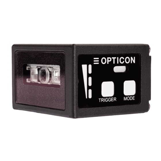
NLV-5201 Specifications Manual 4 Detailed View 1. Scan Window 2. Mounting Holes X X X X X X 4. Buzzer Holes 3. Control Panel 6. Trigger Key 5. Status LED 7. Mode Key Figure 1: Detailed View of NLV-5201... -
Page 12: Basic Operation Mode
Scan Window Light paths of the imager scanner, LED illumination, and aiming. Make sure that the lens is free from dust and dirt before scanning. For more “Cleaning the NLV-5201” on page information, see Mounting Holes Screw holes (two on the bottom and two on the side) that you can use to mount the imager scanner. -
Page 13: Exposure Control
NLV-5201 Specifications Manual Exposure Control Exposure Control determines shutter speed and illumination parameters. Exposure Control can be set to: • Automatic Adjustment • Tuning 5.1.1 Automatic Adjustment Exposure Control By default, Exposure Control is set to Automatic Adjustment. Exposure is automatically adjusted when the reading distance and the barcode to read is not fixed. -
Page 14: Operation Modes And Status
NLV-5201 Specifications Manual Operation Modes and Status Mode Mark Description Normal When the imager scanner is in a read mode, these conditions are used to trigger barcode reading: • Command trigger by serial communication (USB-COM/RS-232C) • External trigger signal (RS-232C) •... -
Page 15: Control Panel Operation Specifications
NLV-5201 Specifications Manual Control Panel Operation Specifications This section describes the operation of the control panel on the side of housing. Mode Trigger Operation Operation Description LED Indicator Mode Trigger Normal Normal operation status. Key for reading Press Mode Test Used when testing the read rate. -
Page 16: Led Indicator Specifications
NLV-5201 Specifications Manual LED Indicator Specifications The status LED’s indicate the read result and USB communication status. In read rate mode, the reading success rate is indicated by these three 3-color LED’s. Normal Mode Status LED Indication Status Reading Success... -
Page 17: Electrical Specifications
NLV-5201 Specifications Manual 6 Electrical Specifications The NLV-5201 consists of these components: • Decoder Section: Decodes 1D and 2D barcodes and OCR fonts from an image scanned by the CMOS sensor camera module. • Communication Control Section: Communicates with a host device. -
Page 18: Interface Specification
NLV-5201 Specifications Manual 8 Interface Specification The NLV-5201 uses these interfaces: • RS-232C • USB (COM/HID) RS-232C Interface This section describes RS-232C serial communications between the imager scanner and a host computer. If the host COM port is not open, the imager scanner cannot send data and will emit an error sound. -
Page 19: Signal Level
NLV-5201 Specifications Manual 8.1.3 Signal Level Signal names are based on signals transmitted from the imager scanner to the host. Signal Levels Voltage (V) Name IN/Out Mark Space -5 to -15 +5 to +15 -3 to -15 +3 to +15... -
Page 20: Rs-232C Interface Cable
The COM interface allows bidirectional serial communication, which supports transmitting commands from the host computer to the imager scanner, as well as receiving barcode data. To use USB-COM, you need to install the latest version of the Opticon USB-COM driver on your host device. -
Page 21: Usb Interface Specifications
NLV-5201 Specifications Manual 8.2.1 USB Interface Specifications The USB interface model is bus powered. No external power supply is needed. Caution: If you are using USB-HID to transmit barcode data, using the host keyboard may cause data to be lost. -
Page 22: Usb Interface Cable
NLV-5201 Specifications Manual 8.2.4 USB Interface Cable USB Interface Cable Specifications Parameter Specification Cable length 1500 mm φ3.8 mm Cable diameter Weight Approx. 70 g Cable material [Unit: mm] 1500 ± 50 Figure 9: USB Interface Cable 9 Optical Specifications... -
Page 23: Aiming Pattern
NLV-5201 Specifications Manual Aiming Pattern Aiming indicates the appropriate reading distance by projecting a bar of green LED light: • The optical axis of the imaging field of view and the center of the horizontal aiming bar coincide at a distance of L=148±20 mm from the front edge of the imager scanner. -
Page 24: Technical Specifications
NLV-5201 Specifications Manual Image Range for UD Models L: Distance from the Front Edge of the Imager Scanner (mm) Horizontal Field of View (FOV) 22.7 29.6 36.5 43.4 57.1 70.9 Vertical Field of View (FOV) 17.0 22.1 27.3 32.4 42.7 53.0... -
Page 25: Barcode Test Labels
NLV-5201 Specifications Manual 10.1 Barcode Test Labels This section describes the barcode labels used when the depth of field was measured. 10.1.1 1D Barcode Test Labels Code 39 Resolution PCS (MRD) Size (mm) No. of Digits 0.10 mm (3.9 mil) 0.9 (80) -
Page 26: Scan Area And Depth Of Field
NLV-5201 Specifications Manual 10.2 Scan Area and Depth of Field The scan area is measured from the front edge of the imager scanner. The depth of field depends on the view angle and symbol length. Depth of field values provided are the typical values measured by tilting the test chart 15°... - Page 27 NLV-5201 Specifications Manual Depth of Field for SR Models = 25°C Resolution Symbology Guaranteed Value Typical Value Type (MRD) Near Near 0.127 mm Code 39 0.9 (0.8) 64 mm 110 mm 53 mm 126 mm (5 mil) (2.5″) (4.3″) (2.1″) (5.0″)
-
Page 28: Figure 12: Scan Area And Depth Of Field
NLV-5201 Specifications Manual 10.2.2 Scan Area and Depth of Field for HD Models 0.076mm (3mil) 0.127mm (5mil) Code 39 0.254mm (10mil) 0.20mm (7.9mil) Code 128 0.33mm (13mil) EAN/UPC 0.127mm (5mil) PDF417 0.254mm (10mil) 0.127mm (5mil) QR Code 0.381mm (15mil) 0.127mm (5.0mil) Data Matrix 0.254mm (10mil) - Page 29 NLV-5201 Specifications Manual Depth of Field for HD Models = 25°C Resolution Symbology Guaranteed Value Typical Value Type (MRD) Near Near 0.127 mm Code 39 0.9 (0.8) 53 mm 63 mm 45 mm 72 mm (1.8″) (5 mil) (2.1″) (2.5″) (2.8″)
- Page 30 NLV-5201 Specifications Manual 10.2.3 Scan Area and Depth of Field for UD Models 0.076mm (3mil) 0.127mm (5mil) Code 39 0.254 (10mil) 0.33mm (13mil) EAN/UPC 0.084mm (3.3mil) QR Code 0.381mm (15mil) 0.084mm (3.3mil) Data Matrix 0.254mm (10mil) [Unit: mm] Figure 14: Scan Area and Depth of Field for UD Models...
-
Page 31: Printed Contrast Signal (Pcs)
NLV-5201 Specifications Manual Depth of Field for UD Models = 25°C Resolution Symbology Guaranteed Value Typical Value Type (MRD) Near Near 0.076 mm Code 39 0.9 (0.8) 35 mm 56 mm 28 mm 65 mm (3 mil) (1.4″) (2.2″) (1.1″) (2.6″) -
Page 32: Minimum Resolution
NLV-5201 Specifications Manual 10.4 Minimum Resolution 10.4.1 Minimum Resolution for SR Models “Barcode Test Labels” on page For details, see Minimum Resolution Barcodes Barcode Type Barcode Symbology Minimum Resolution 1D Barcode Code 39 0.1 mm GS1 DataBar GS1 DataBar Limited 0.169 mm... -
Page 33: Barcode Width
NLV-5201 Specifications Manual Minimum Resolution Conditions Condition Description Distance 43 mm from the front edge of the imager scanner α = 0°, β =+15°, γ = 0° Angle R = ∞ Curvature 10.5 Barcode Width Barcode width: 100 mm Barcode Width Conditions... -
Page 34: Pitch, Skew And Tilt
NLV-5201 Specifications Manual 10.6 Pitch, Skew, and Tilt Pitch, Skew, and Tilt Orientation Description α = ±65° (SR models) Pitch α = ±60° (HD models) α = ±50° (UD models) β = ±65° (SR and HD models) Skew β = ±50° (UD models) γ... -
Page 35: Curvature
NLV-5201 Specifications Manual 10.7 Curvature R ≧ 20 mm (SR and HD models) 0.33 mm 12-digit UPC R ≧ 25 mm (UD models) Note: Decoding may fail due to specular reflection. Curvature Conditions Condition Description “Barcode Test Labels” on page Barcode Sample UPC, 0.33 mm. -
Page 36: Motion Tolerance
NLV-5201 Specifications Manual 10.8 Motion Tolerance 2.54 m/s (UPC 100%) (SR models) 1.0 m/s (QR Code) (HD models) Motion Tolerance Conditions Condition Description Ambient Temperature Room temperature and room humidity and Humidity Ambient Light 500 lux to 1000 lux (on the surface of the barcode) -
Page 37: Scan Speed
NLV-5201 Specifications Manual 10.9 Scan Speed Scan speed only applies to SR and HD models. Number of scans per second: • 1D Barcode: 40 scans/sec. • 2D Barcode: 25 scans/sec. Scan Speed Conditions Condition Description Ambient Temperature Room temperature and Room humidity... -
Page 38: Auto Trigger
NLV-5201 Specifications Manual 10.10 Auto Trigger In auto trigger mode, the imager scanner detects an abrupt change in brightness in the scan area and automatically starts scanning. Auto trigger is activated when a black sheet of paper is placed in front of a gray sheet of paper. You can configure auto trigger. -
Page 39: Indicator Specifications
NLV-5201 Specifications Manual 10.11 Indicator Specifications Indicator Description Status LED Upper panel, 3 color LED: red, orange, and green Buzzer Adjustable volume and tone 10.12 Imager Specifications Specification Description Image data format Windows Bitmap, JPEG Shades of gray 1024, 256, 16, 2... -
Page 40: Ambient Light Immunity
NLV-5201 Specifications Manual 11.3 Ambient Light Immunity Scanning performance is optimal when the illumination on the surface of a barcode is between zero and these values: Incandescent Light: 10,000 lux Fluorescent Light: 10,000 lux Sunlight: 100,000 lux Note: To achieve the best scanning performance, make sure that direct ambient light and specular reflection do not enter the light receiving section of the imager scanner. -
Page 41: Cable Strength
NLV-5201 Specifications Manual 11.6 Cable Strength The cable is designed to withstand the conditions of the following cable strength test. Cable Strength Test: Attach the scanner to a stationary object. Pull the cable with a force of 25 N (2.5 kgf, static loading) for 60 seconds. -
Page 42: Drop Impact Resistance
NLV-5201 Specifications Manual 11.9 Drop Impact Tolerance 11.9.1 Drop Impact Tolerance of the Imager Scanner The imager scanner is designed to withstand the conditions of the following drop test. Drop test: Drop the imager scanner a total of 15 times (3 times for each position shown in the next illustration) from a height of 75 cm onto a concrete floor. -
Page 43: Radio Frequency Electromagnetic Field Amplitude Modulation
NLV-5201 Specifications Manual 11.11 Radio Frequency Electromagnetic Field Amplitude Modulation The Radio Frequency Electromagnetic Field Amplitude Modulation Test is compliant with IEC- 61000-4-3. Radio Frequency Electromagnetic Field Amplitude Modulation Condition Description Frequency 80 to 1000 MHz Level 3 V/m 80% (AM) 11.12 Power Frequency Magnetic Field... -
Page 44: Rohs
NLV-5201 Specifications Manual 13 RoHS The NLV-5201 is compliant with RoHS. RoHS Directive The restriction of the use of certain hazardous substances in electrical and electronic equipment, 2011/65/EU. 14 Reliability The imager scanner will perform reliably if it is operated under normal operating conditions in the range of advised operating temperature and humidity without excessive electrical or mechanical shock. -
Page 45: Cleaning Nlv-5201
To clean the scan window and housing, rub gently with either a soft dry cloth or a damp cloth with mild detergent. Figure 25: Cleaning the NLV-5201... -
Page 46: Product Labels
NLV-5201 Specifications Manual 17 Product Labels 17.1 Serial Number Label This serial number label is affixed to the NLV-5201. The serial number consists of 6 digits in the box labeled “SN”. Figure 26: Serial Number Label X X X X X X Figure 27: Serial Number Label Affixed to the NLV-5201 17.2 Address Label... -
Page 47: Packaging Specifications
Outer dimensions are approximately W: 240 mm, D: 110 mm, H: 37 mm Weight is approximately: 185 g Fold Fold NLV-5201 Put NLV-5201 into packing bag. Fold both sides and tape it to prevent it from moving inside. PACKING BAG QUICK START GUIDE... -
Page 48: Collective Packaging Specification
NLV-5201 Specifications Manual 18.2 Collective Packaging Specification Carton box: 50 pieces, NLV-5201 Assembled package size is approximately W: 575 mm × D: 505 mm × H: 200 mm Weight is approximately: 10 kg Put the box to the carton box in this direction. -
Page 49: Mechanical Drawing
NLV-5201 Specifications Manual 19 Mechanical Drawing Imaging Lens Aiming Lens Plastic Mask Illumination LED Lens Mounting Holes M3 Depth 3.5 Status LED 35.9 41.1 18.8 X X X X X X Trigger Key Mode Key Buzzer Holes Mounting Holes M3 Depth 3.5 10.9... -
Page 50: Default Factory Settings
NLV-5201 Specifications Manual 20 Default Factory Settings 20.1 Barcode Default Settings 20.1.1 1D Barcode Default Settings Only positive image 1D barcodes can be decoded. These suffix values are supported: • USB-HID: “ENTER” • USB-COM/RS-232C: “CR” 1D Barcode Default Settings Minimum... -
Page 51: Postal Code Default Settings
NLV-5201 Specifications Manual 20.1.2 Postal Code Default Settings These suffix values are supported: • USB-HID: “ENTER” • USB-COM/RS-232C: “CR” Postal Code Default Settings Symbology Enabled Minimum Digits Chinese Post Matrix 2 of 5 Korean Postal Authority Intelligent Mail Barcode ... -
Page 52: Composite Gs1 Default Settings
NLV-5201 Specifications Manual 20.1.4 Composite GS1 Default Settings These suffix values are supported: • USB-HID: “ENTER” • USB-COM/RS-232C: “CR” Composite GS1 Default Settings Symbology Enabled ✓ [Composite GS1 DataBar] CC-A CC-B Limited CC-A Limited CC-B Expanded CC-A Expanded CC-B ✓... -
Page 53: Barcode Default Settings
NLV-5201 Specifications Manual 20.1.5 2D Barcode Default Settings These suffix values are supported: • USB-HID: “ENTER” • USB-COM/RS-232C: “CR” 2D Barcode Default Settings Positive/Negative Symbology Enabled Tuning Image Mirroring ✓ ✓ PDF417 Positive ✓ Micro PDF417 Positive Codablock F* ✓... -
Page 54: Read, Trigger, And Buzzer Default Settings
Send “new line key “after data Enabled Send “TAB key” after data Disabled Send “→ key” after data Disabled Other CDC-ACM compliant (USB-COM)* To use USB-COM, you need to install the latest version of the Opticon USB-COM driver on your host device.
Need help?
Do you have a question about the NLV-5201 and is the answer not in the manual?
Questions and answers