Table of Contents
Advertisement
Quick Links
Download this manual
See also:
Specification Manual
Advertisement
Table of Contents
Troubleshooting

Related Manuals for Opticon NLV-5201


Summary of Contents for Opticon NLV-5201
- Page 1 NLV-5201 Fixed Position 2D Imager Scanner User's Manual...
- Page 2 Please read this manual carefully before installing or using the product. Serial Number A serial number appears on all Opticon products. This official registration number is directly related to the device purchased. Do not remove the serial number from your Opticon device. Removing the serial number voids the warranty.
-
Page 3: Caution And Warning
・Do not swing the product around by the cable. It may cause injury or damage to the device. Cable handling ・Do not wrap NLV-5201 cable around a host device (PC, tablet etc.). It may cause breakage to the strain relief and the cable jacket, and could cause malfunction, overheating, smoke and fire. - Page 4 ( 1 ) this device may not cause harmful Interference, and ( 2 ) this device must accept any interference received, including interference that may cause undesired operation. VCCI クラス B この装置は、クラスB機器です。この装置は、住宅環境で使用することを目的としています が、この装置がラジオやテレビジョン受信機に近接して使用されると、受信障害を引き起こすこ とがあります。 取扱説明書に従って正しい取り扱いをして下さい。 VCCI-B Disclaimer: OPTOELECTRONICS CO.,LTD. Will not bear any responsibility in case of malfunction, accident, repair and damage assurance. NLV-5201 User's Manual...
- Page 5 Revision History Document Name : NLV-5201 User's Manual Edition Date Page Section Description of Changes Prelimina 2019/02/22 Initial release NLV-5201 User's Manual...
-
Page 6: Table Of Contents
Solution for Specular Reflection of the External Illumination.......... 27 2.12 Exit Window Placement ......................28 2.12.1 Exit Window Material ...................... 28 2.12.2 Solution for Specular Reflection of the Illumination ............29 Configurations ..........................30 Configuring with Commands ....................31 NLV-5201 User's Manual... - Page 7 Handshaking (Flow Control) ................... 49 5.1.5 Inter Character Delay (RS-232C) ................... 54 5.1.6 Trouble Shooting (RS-232C) ..................54 USB-HID ..........................55 5.2.1 USB-HID Basic Information .................... 56 5.2.2 Connection Confirmation (USB-HID) ................57 5.2.3 NumLock CapsLock control .................... 57 NLV-5201 User's Manual...
- Page 8 7.4.1 Bank Selection ........................ 81 7.4.2 Bank Specify Trigger ...................... 81 7.4.3 Confirm Current Bank ..................... 81 7.4.4 Initialize Bank ........................81 Read Options ..........................82 Read Modes Overview ......................83 8.1.1 Read Operation Flow ...................... 83 NLV-5201 User's Manual...
- Page 9 Interleaved 2 of 5 and S-Code ..................112 9.3.6 Code128 ........................113 9.3.7 IATA ..........................114 9.3.8 MSI/Plessey ........................114 9.3.9 UK/Plessey ........................114 9.3.10 Telepen ......................... 114 9.3.11 Code 11 ........................115 9.3.12 Korean Postal Authority ....................115 9.3.13 GS1 DataBar ........................ 116 NLV-5201 User's Manual...
- Page 10 Case Conversion ........................135 Appendix ............................ 136 11.1 Code ID Table ........................137 11.1.1 Opticon Code ID prefix / suffix value ................137 11.1.2 Code Option AIM / ISO15424 Code ID prefix / Suffix value ......... 138 11.2 NLV-5201 Specification Overview ..................142 11.2.1...
-
Page 11: Abstract
Chapter-1 Abstract 1 Abstract This document provides the user’s manual for the NLV-5201 2D handy scanner (hereafter called “scanner”) 1.1 Feature of the Scanner 1.2 Usage of the Scanner 1.3 Flow to Integrate NLV-5201 User's Manual... -
Page 12: Features Of The Scanner
Chapter-1 Abstract Features of the Scanner The NLV-5201 is a fixed position 2D imager scanner that enables high speed reading of a standard barcode, 2D code and OCR font. Main features are as follows: ● High-speed reading The high-speed CMOS sensor (100fps) and high-speed CPU enables stress-free scanning and fast response from fast movement and poor/bright lighting conditions. -
Page 13: Usage Of The Scanner
Tuning Auto Adjustment (default) When reading distance and the code to read is Adjust exposure automatically when the fixed, reading will stabilized by setting the optimum reading distance and the code to read is not exposure. fixed. NLV-5201 User's Manual... -
Page 14: Flow To Integrate
Reading and Timing ● → (Refer to 8) Read options ● → (Refer to 10) String Options 4. Tuning and Testing Tune and test in the acturla envirioment. ● → (Refer to 7) Tuning and bank function Integrate NLV-5201 User's Manual... -
Page 15: Flow To Integrate For General Uses
Code Options ● → (Refer to 10) String Options ● → (Refer to 8) Read Options 4. Create Setting Menu Create a 2D menu code suitable for operation. ● → (Refer to 3.1.2) 2D menu code Integrate NLV-5201 User's Manual... -
Page 16: Before Using
2.5 Depth of Field and Focus Type 2.6 Detailed View 2.7 Operation Mode and Control Panel Description 2.8 Operation Transition 2.9 Installation of the Scanner 2.10 Scan Area 2.11 Scanned Media and Placement 2.12 When Placing Exit Window NLV-5201 User's Manual... -
Page 17: Model Details
Chapter-2 Before Using Model Details The NLV-5201 model name is constructed by a combination of following. Model Optional Focus Interface Cable length name AC Adapter -RS232C(LE) None -USB None NLV-5201 -USB-COM None -RS232C(9P) -RS232C 2.1.1 Standard The following specs are the standard products. -
Page 18: Package Contents
Package Contents Following items are packed to this product. Please check before using. USB-HID / USB-COM Interface Model Following are included to USB interface model. NLV-5201 Quick Start Guide Scanner with USB cable (1 copy) RS-232C Interface Model Following are packed to RS-232C interface model. -
Page 19: Connect To The Host
* USB-COM and USB-HID interface can be changed by the setting. * For the USB-COM interface model, the Opticon USB-COM driver must be installed on your host device. * While using USB-COM and not connected to the host, the scanner makes an error sound when reading. - Page 20 External NG output terminal Black S-GND Gray Blue Green White (Black) Shield GND Heat shrinkable tube Loose end Circuit External device NLV-5201 DC 5V OK / NG MAX DC 24V Load Barcode reader main circuit Trigger S-GND F-GND NLV-5201 User's Manual...
-
Page 21: How To Read
Reading Reference Standard mode (SR): Approx. 113 cm Scan Area (Refer to 2.10) Distance (Refer to 2.5.1) High Resolution model (HD): Approx. 63 cm (Refer to 2.5.2) Ultra High Resolution model (UD): Approx. 43 mm (Refer to 2.5.3) NLV-5201 User's Manual... -
Page 22: Depth Of Field And Focus Type
0.254mm (10mil) * The depth of field is the typical value measured by tilting the test chart 15° from the optical axis. (25C°) * Refer to 11.2.2 Technical Specifications Standard Model Reading Depth of Field for specified value. NLV-5201 User's Manual... -
Page 23: High Resolution Model (Hd) Depth Of Field
* The depth of field is the typical value measured by tilting the test chart 15° from the optical axis. (25C°) * Refer to 11.2.2 Technical Specifications High Resolution Model (HD) Reading Depth of Field for specified value. NLV-5201 User's Manual... -
Page 24: Ultra High Resolution Model (Ud) Depth Of Field
* The depth of field is the typical value measured by tilting the test chart 15° from the optical axis. (25C°) * Refer to 11.2.2 Technical Specifications Ultra High Resolution model (UD) Reading Depth of Field for specified value. NLV-5201 User's Manual... -
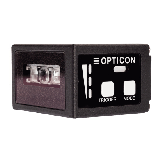
Page 25: Detailed View
Default is trigger key. When selecting mode, it operates as execution Trigger Key key. The key to select and cancel the mode. Mode Key Shift to bank select mode by long press. Mode key can be disabled, refer to 3.3.9 for detail. NLV-5201 User's Manual... -
Page 26: Operation Mode And Control Panel Description
Area to register the exposure etc. adjusted in the tuning mode. 1-7 can Bank be register to the bank, default is 1. Aiming lights and if code can be read, displays whether the code is close Aiming mode to the center coordinate of the image sensor to LED indicator. NLV-5201 User's Manual... -
Page 27: Control Panel Operation Specifications
5 seconds, it enters to the initialization standby. becomes initialization Initialize Initialized by pressing trigger key with that status, standby. And initialize by and initialization standby will be cancel by pressing pressing trigger key again. mode key. NLV-5201 User's Manual... -
Page 28: Led Indicator Specifications
The LED of the bank currently used will blink by pressing the mode key for more than 2 seconds. Bank No. No.1 No.2 No.3 No.4 No.5 No.6 No.7 indication * Status LED legend : OFF : Blinking : ON NLV-5201 User's Manual... -
Page 29: Buzzer And Led Indicator
* Low: around 1000 Hz, Low middle: around 1000-2000 Hz, Middle low: around 2500 Hz, Middle: around 3000 Hz, Middle high: around 3500 Hz, High: around 4000Hz. * Refer to 4. Indicator for setting detail. * Above is the definition of the representative status and does not indicate all of the operations. NLV-5201 User's Manual... -
Page 30: Operation Transition
The reading operation can be stopped by a successful decode, a stop Reading operation stop* command, or a timeout period after release of the trigger. * "Reading operation stop” is configured using commands. This cannot be done while using USB-HID interface. NLV-5201 User's Manual... -
Page 31: Auto Trigger
Auto-trigger mode will sleep after 60 seconds (default time). This sleep Auto trigger sleep time can be re-configured or disabled. Reading operation stop* Operation of the scanner is stopped. * "Reading operation stop” is configured using commands. This cannot be done while using USB-HID interface. NLV-5201 User's Manual... -
Page 32: Operation Invalid Transition Diagram
For USB-COM and RS-232C, scanner operation can be disabled by command’s serial communication. When disabled, auto trigger operation becomes invalid. Read operation enable command Read Operation Read Operation Enable Disable Read operation disable command Refer to 3.3.6 for setting command. NLV-5201 User's Manual... -
Page 33: Installation Of The Scanner
X X X X X X Mounting Holes M3 Depth 3.5 [Unit: mm] 10.9 Dimensions: Approx. 41.1 (W) ×33.0 (H) ×24.0 (D) Weight: Approx. 30 g (excluding cable) Cable: 1.5 m Please contact sales for 3D CAD data. NLV-5201 User's Manual... -
Page 34: Scan Area
Scan Area Image range is as follows. 2.10.1 Image Range NLV-5201 image range is as follows. Install a frame with sufficient clearance for the field of view. The range is ±5% from the following values. Image Range L: Distance from the front edge of scanner [mm] Horizontal FOV [mm] 29.6 43.4 57.1 70.9 84.7 98.5 112.3 126.0... -
Page 35: Optical Path
HD Focus (63 mm) Illumination LED Vertical Field of View Aiming (LED) Illumination LED *Obtain the image in the actual environment and evaluate it. The software tools for image capture can be found on the Opticon website. NLV-5201 User's Manual... -
Page 36: Scanned Media And Placement
Background *For the background, use non-specular surface within the image range. *Obtain the image in the actual environment and evaluate it. The software tools for image capture can be found on the Opticon website. NLV-5201 User's Manual... -
Page 37: Solution For Specular Reflection Of The External Illumination
It is recommended to shield the reading position from strong ambient light. Shade Scanned target *Obtain the image in the actual environment and evaluate it. The software tools for image capture can be found on the Opticon website. NLV-5201 User's Manual... -
Page 38: Exit Window Placement
● Hard coated acrylic sheets are readily available. Such a coating greatly enhances anti-scratch properties without degrading the optical characteristics of the acrylic material. Recommended acrylic material: Nitto Jushi Kogyo Co., Ltd. Clarex Precision Thin Sheet MITSUBISHI CHEMICAL CO., LTD. Shinkolite NLV-5201 User's Manual... -
Page 39: Solution For Specular Reflection Of The Illumination
* Use of AR coated material for the exit window is recommended. * External light is not factored in. * Confirm that there is no reflection of the LED illumination off the exit window by acquiring images from the scanner. NLV-5201 User's Manual... -
Page 40: Configurations
Chapter-3 Configurations 3 Configurations This chapter explains the scanner configuration, default setting and saving setting, and basic commands. 3.1 Configuring with Commands 3.2 Command Packet Sending Precautions 3.3 Basic Commands NLV-5201 User's Manual... -
Page 41: Configuring With Commands
* Commands entered in the “command:” box of this utility do not require the beginning command header <ESC>. The command or commands will be sent to the reader upon a ENTER key or a click of the [Send] button NLV-5201 User's Manual... -
Page 42: Configuring With 2D Menu
(Separator) ← Multiple sets allowed “Any menu command” (U2 etc) “@” (Separator) “ZZ” (END menu) “@” (Separator) “OTPO_UNEM@” (Stop key) ● 2D menu code can be created at “UniversalConfig”. Print *Please contact sales offices for the tools. NLV-5201 User's Manual... -
Page 43: Configuring With 1D Menu Code
* 1D Menu codes encode an ID consisting of two to five alphanumeric characters. 1D Menu codes are Code39 labels with modified start/stop characters and therefore the scanner will not acknowledge a 1D menu code as a normal barcode. ● Menu barcode can be created at “UniversalConfig”. Print *Please contact sales offices for the tools. NLV-5201 User's Manual... -
Page 44: Command Packet Sending Precautions
The Active Settings can be returned to the factory default settings. Set the command that corresponds to the interface being used. Item Command Interface Description Remark USB-HID Restore USB-HID to factory default settings Factory Default [C01 USB-COM Restore USB-COM to factory default settings Settings RS-232C Restore RS-232C to factory default settings NLV-5201 User's Manual... -
Page 45: Save Settings
* Place “[BAQ” at the end of command packet to be saved. * To save both “Custom settings” and “Active Settings” at same time, send “[BAQZ2”. * Custom settings for more than 30,000 times may destroy memory. When setting frequently, avoid saving every time. NLV-5201 User's Manual... -
Page 46: Basic Commands
Q1 Q0 Disable when using external trigger signal.* Q2 Q1 Enable when using command trigger or auto trigger. Q2 Q0 Disable when using command trigger or auto trigger.* * Indicates that 1D menu code reading is prohibited. NLV-5201 User's Manual... -
Page 47: Image Settings
[EFU[E8I Disable Enable 180° rotated image [EFV[E8I Enable Enable Right (Device) Top (Device) Bottom (Device) Left (Device) [①Normal image] [②Horizontal mirror image] Top (Device) Top (Device) Bottom (Device) Bottom (Device) [④180° rotated image] [③Vertical mirror image] NLV-5201 User's Manual... -
Page 48: Disable Reading Operation
Use this command to restart the scanner. Item Command Description Remark Software reboot Reboot the scanner 3.3.9 Enable/Disable Mode Key Item Command Description Default Disable mode key Enable/Disable [EHB Enable mode key Mode key Control Panel Mode Key NLV-5201 User's Manual... -
Page 49: Direct Numerical Input Command
When a command requires additional numerical input, the commands below can be used. Use these in one packet together with the command that requires the numerical input. Item Command Description Remark Input in a Direct input specified numerical values format NLV-5201 User's Manual... -
Page 50: Indicator Options
Chapter-4 Indicator Options 4 Indicator Options This chapter describes the options for Buzzer and Good Read LED. 4.1 Buzzer 4.2 Status LED 4.3 Good Read Aiming 4.4 Indicator in General NLV-5201 User's Manual... -
Page 51: Buzzer
4-digit numerical command. Frequency range normally use is 2000 to 4000 Hz. The scanner most resonance around 2750 Hz. Item Command Description Default Buzzer tone Numerical setting of 2600 Hz buzzer tone frequency frequency [DF0 (1-9999) setting (1000a+100b+10c+d)[Hz] NLV-5201 User's Manual... -
Page 52: Start-Up Buzzer
When the good read buzzer is disabled, this setting will be forcibly disabled. Item Command Description Default Disable intermediate buzzer Intermediate buzzer [EBY Enable intermediate buzzer * Intermediate buzzer frequency: 5000 Hz (5 KHz), duration: 10 ms NLV-5201 User's Manual... -
Page 53: Status Led
The status LED lights up after a code was successfully decoded and the data was output. This can be disabled or set for several durations. Item Command Description Default Disable indicator [XT8 Indicator duration: 100 ms Status LED Indicator duration: 200 ms Indicator duration: 400 ms Indicator duration: 800 ms NLV-5201 User's Manual... -
Page 54: Good Read Aiming
10b + c 00-99 x10 ms 50 ms Setting example) - Lights 2 times (After 100 ms: Default) Command: [EF3Q0Q0Q2 - Set first indicator duration after reading to 500 ms Continue to above indicator frequency setting Command: [EF3Q1Q5Q0 NLV-5201 User's Manual... -
Page 55: Indicator In General
Common settings for each indicator are described below. 4.4.1 Indicator Timing The indicators can be activated after decoding a code and before or after transmitting the data. Item Command Description Default Remark soon after Before data transmission decoding Indicator timing After data transmission NLV-5201 User's Manual... -
Page 56: Interface
Chapter-5 Interface 5 Interface The scanner support RS-232C, USB-COM and USB-HID interface. This chapter explains each interface in detail. 5.1 RS-232C 5.2 USB-HID 5.3 USB-COM 5.4 Common Settings NLV-5201 User's Manual... -
Page 57: Rs-232C
Chapter-5 Interface RS-232C This chapter explains RS-232C interface settings. 5.1.1 RS-232C Basic Information 5.1.2 Baud Rate (Transfer Speed) 5.1.3 Character Format 5.1.4 Handshaking (Flow Control) 5.1.5 Inter Character Delay (RS-232C) 5.1.6 Trouble Shooting (RS-232C) NLV-5201 User's Manual... -
Page 58: Rs-232C Basic Information
Item Command Description Default Remark 300 bps 600 bps 1200 bps 2400 bps 4800 bps Enabled only with Baud rate “Z2” 9600 bps 19200 bps 38400 bps 57600 bps 115200 bps NLV-5201 User's Manual... -
Page 59: Character Format
"Z2" (save command in non-volatile memory) needs be used after these commands to activate and save the new configuration. Item Command Description Default Remark No handshake Busy/ready Enabled after sending “Z2” Handshaking Modem ACK/NAK ACK/NAK NO RESPONSE NLV-5201 User's Manual... - Page 60 CTS line to be tuned on. If the CTS line is not turned on within the time specified, the data transmission will be aborted. Scanner Host System Cannot Receive Command Send Software Decode Wait to Send Wait to Buzzer Finish Send Send NLV-5201 User's Manual...
- Page 61 CTS. If, while RTS is ON, the CTS line is not ON for a certain configurable period, the scanner will terminate the transmission with an error indication of the buzzer. Scanner Host System Transmit Data Send Software Decode Wait to Send Wait to Buzzer Finish Send Send NLV-5201 User's Manual...
- Page 62 LabelB Read Finish Processing <ACK/NAK Flow chart> Start of transmission Transmit data Start 1 sec. timer As configured Response received Response = NAK Timer ended Response = ACK Response = DC1 ERROR Buzzer ERROR Buzzer GOOD READ Buzzer NLV-5201 User's Manual...
- Page 63 If there is no response within 100 ms then the scanner terminates transmission with the good read buzzer. <ACK/NAK No Response Flow Chart> Start of transmission Transmit data Start 100 ms. timer Response received Response = NAK Timer ended Response = ACK Response = DC1 GOOD READ Buzzer ERROR Buzzer GOOD READ Buzzer NLV-5201 User's Manual...
-
Page 64: Inter Character Delay (Rs-232C)
Set the 5.1.5 inter-character delay according to the host PC’s processing Garbled characters speed. Confirm that code to be read matches to the character code of the communication tool. Line-break is Check the line-break setting of the communication tool. doubled NLV-5201 User's Manual... -
Page 65: Usb-Hid
Interface USB-HID This chapter explains USB-HID interface settings. 5.2.1 USB-HID Basic Information 5.2.2 Connection Confirmation (USB-HID) 5.2.3 NumLock CapsLock control 5.2.4 Data Output Speed (USB-HID) 5.2.5 Inter Character Delay (USB-HID) 5.2.6 Keyboard Language 5.2.7 Trouble Shooting (USB-HID) NLV-5201 User's Manual... -
Page 66: Usb-Hid Basic Information
Set according to the keyboard language. Initial value: English (USA) Set according to reading symbol encode Initial value: not use Character code data. character code Output mode Set when outputting Chinese-character. Initial value: output as it is NLV-5201 User's Manual... -
Page 67: Connection Confirmation (Usb-Hid)
*2. When starting transmits, send CapsLock and invert status. Use when CapsLock is always ON. Return to CapsLock status when sending is completed. *3. Control CapsLock status to display as the original string. Return to original CapsLock status when transmit is complete. NLV-5201 User's Manual... -
Page 68: Data Output Speed (Usb-Hid)
Default No delay Delay = 1 Delay = 2 Delay = 3 Delay = 4 Inter character delay Delay = 5 Delay = 6 Delay = 7 Delay = 8 Delay = 9 Delay = 10 NLV-5201 User's Manual... -
Page 69: Keyboard Language
Windows 1250 [BAY Hungarian Windows 1250 [BPJ Turkish Windows 1254 [EF4 Russian English Windows 1251 [EF5 Russian Cyrillic Windows 1251 [BAZ Brazilian Windows 1252 [E76 Chinese Windows 1252 [E77 Korean Windows 1252 [E78 Taiwanese Windows 1252 Japanese Shift-JIS NLV-5201 User's Manual... -
Page 70: Trouble Shooting (Usb-Hid)
• The trigger cannot be turned on until the connection between PC and Does not start reading USB is established. Please refer to above “The scanner does not even trigger key is appear in Device Manager”. turned on. NLV-5201 User's Manual... -
Page 71: Usb-Com
Chapter-5 Interface USB-COM This chapter explains USB-COM interface settings. 5.3.1 USB-COM Basic Information 5.3.2 Integration (USB driver) 5.3.3 Connection Confirmation (USB-COM) 5.3.4 Fixed UBS-COM Port 5.3.5 Connection Method 5.3.6 COM to HID Output 5.3.7 Trouble Shooting (USB-COM) NLV-5201 User's Manual... -
Page 72: Usb-Com Basic Information
5.3.3 Connection Confirm USB-COM interface, confirm the connection by following procedure. For Windows 10 Install Opticon USB driver. 1. Connect the scanner to the PC. 2. Right-click "Windows icon" and select "Device Manager". 3. Open "Ports (COM & LPT)". NLV-5201 User's Manual... -
Page 73: Fixed Usb-Com Port
In case multi byte character is not output correctly with USB-HID, this can be solved by using WIME. Windows PC Scanner Scanner Output to focused application Output to focused application USB-COM USB - COM as character information as character information Communication Communication NLV-5201 User's Manual... -
Page 74: Trouble Shooting (Usb-Com)
Please refer to the tool help or manual. • Reboot the PC. • Confirm that code to be read matches to the character code of the Garbled characters communication tool. • Check the line-break setting of the communication tool. Line-break is doubled NLV-5201 User's Manual... -
Page 75: Common Settings
The following menu codes / commands are provided for the data buffer mode setting. Item Command Description Default [D80 Data buffer disable Data buffer mode [D81 Data buffer enable * * When handshaking is configured (refer to 5.1.4), this setting is ignored and Data Buffer Mode is disabled. NLV-5201 User's Manual... -
Page 76: Reading And Timing
Chapter-6 Reading and Timing 6 Reading and Timing This chapter describes the read timing and various timings of the scanner. 6.1 Reading and Trigger Control 6.2 OK/NG Signal NLV-5201 User's Manual... -
Page 77: Reading And Trigger Control
When decoding successes, green LED on the side panel Refer to Status LED of housing lights. When decoding success, the buzzer sounds. Refer to Buzzer When decoding success, aiming can be turned on. Refer to Good Read Aiming NLV-5201 User's Manual... -
Page 78: Command Trigger Control
“Y” Command Command Command Scan time When effective read time is set, it stops reading when the set time elapses. Also, it stops when sending “Y” commands etc. “Z” Command Command Read time option (Configured) Scan time NLV-5201 User's Manual... -
Page 79: External Trigger Signal Control
When external trigger signal is not used and if there is a possibility of noise generation, disable the signal. Item Command Description Default Disable external trigger signal reception External trigger reception [EGO Enable / Disable Enable external trigger signal reception NLV-5201 User's Manual... -
Page 80: Read Time Setting
(effective range) Setting of extended read time Extended read time Synchronize [DF7 (1000a+100b+10c+d) numerical setting with trigger [x10ms] Example when read time 500ms) <Esc>[DF7Q0Q0Q5Q0<CR> 0050 x 10 = 500 ms *Setting is in unit of 10 ms. NLV-5201 User's Manual... -
Page 81: Trigger Delay
Description Default Trigger delay time Trigger delay [DEC 0 ms (1000a+100b+10c+1d)x[10ms] The timing diagram of the trigger delay is as below. Trigger signal “Z” Command Command Trigger delay Trigger delay time Imaging and Decoding Scan Data Data NLV-5201 User's Manual... -
Page 82: Decode Timeout
Decode timeout can limit decode processing time for 1 image. Item Command Description Default Decode Trigger delay time [EAV 0 ms* timeout (1000a+100b+10c+1d)x[10ms] * Decode timeout = 0 means function is disabled. Process decoding for 1 image until the end. Processing time depend on the image. NLV-5201 User's Manual... -
Page 83: Ok/Ng Signal
[X*R Disable OK/NG signal The basic flow chart is shown below. Reading start Clear OK/NG signal (Inactive) Reading successes? Fail Successes OK/NG Signal OK/NG Signal Enable? Enable? Enable Enable Disable Disable OK signal active NG signal active NLV-5201 User's Manual... -
Page 84: Ok/Ng Signal Behavior Settings
[X*G 10 ms [X*H 20 ms [X*I 30 ms [X*J 40 ms OK/NG signal [X*K 50 ms One Shot [X*L 60 ms Active time [X*M 70 ms [X*N 80 ms [X*O 90 ms [X*P 100 ms NLV-5201 User's Manual... -
Page 85: Tuning And Bank Function
Chapter-7 Tuning and Bank Function 7 Tuning and Bank Function This chapter describes the tuning and bank function of the scanner. 7.1 Tuning Overview 7.2 Tuning 7.3 Reading Test 7.4 Bank Function NLV-5201 User's Manual... -
Page 86: Tuning Overview
Also, you can find the optimum installation condition by using UniversalTuningTool. By using the tuning function and adjusting the exposure range, the user can improve performance of the scanner for scan-in-motion applications. Please contact sales offices for the tools. NLV-5201 User's Manual... -
Page 87: Tuning Setting Flow
Set additional codes if necessary.* : Setting of Readable Codes (Caution) Since tuning adjustment value differs for each scanner, tuning needs to be performed for each scanner. * The additional code needs to be same distance and reflectance. NLV-5201 User's Manual... -
Page 88: Tuning
Read rate in Min/Max of read Read Line Type Speed Gain 10 times times in 10 times Data Break *2. The output when tuning failed or stopped in middle. Tuning failed<CR> Indicate tuning failed or stopped and line break. NLV-5201 User's Manual... -
Page 89: Setting The Exposure Adjustment Range Of Tuning
Indicate adjustment of sensor gain and line break. To reset exposure adjustment range, send the following command. Item Command Description Remark Reset exposure Reset the exposure adjustment range of the [DT5 adjustment range current bank to initial setting. NLV-5201 User's Manual... -
Page 90: Reading Test
BANK 1:RATE 100[%]:TIME 25 - 26[ms]:123456789<CR> BANK 1:RATE 100[%]:TIME 24 - 28[ms]:123456789<CR> BANK 1:RATE 100[%]:TIME 24 - 27[ms]:123456789<CR> BANK 1:RATE 100[%]:TIME 24 - 26[ms]:123456789<CR> Bank Read rate in Max/Min read time Read Line 10 times in 10 times data break NLV-5201 User's Manual... -
Page 91: Bank Function
Initialize all banks setting parameter. * Settings that are not included in the bank parameters will not be initialized. * When bank is initialized, the scanner operates with the default bank as long as bank with effective parameter is not selected. NLV-5201 User's Manual... -
Page 92: Read Options
Chapter-8 Read Options 8 Read Options This chapter describes the read options for the scanner. 8.1 Read Modes Overview 8.2 Auto Trigger 8.3 Illumination and Aiming NLV-5201 User's Manual... -
Page 93: Read Modes Overview
Continues read Limit to the testing, continuously read the same data. Batch reading Batch reading with a specified rule is possible by using data edit function. Reading Complete Reading success, Reading complete operation, Read timeout NLV-5201 User's Manual... -
Page 94: Read Modes
Default: 20 Number of codes [D3P that a barcode is read twice. Effective range: not read the same Set; a:100 digits / b:10 digits / 1 to 200 data c:1 digit NLV-5201 User's Manual... - Page 95 Example: Read multiple codes sequentially with single trigger. Double read reset time Double read reset time ● Continues Read To confirm the reading performance in test etc., read continuously even with the same code. Example: Reads continuously even with the same code. NLV-5201 User's Manual...
-
Page 96: Batch Reading
The Universal Config utility has some support for Data Editing, but it is an advance language and may need extra support. Please contact technical support or your sales office for more information on this. NLV-5201 User's Manual... -
Page 97: Auto Trigger
When a code with different data is read, this will be reset. Default Item Command Description (valid range) Double read reset time 700 ms Double read reset time [D3R (1000a+100b+10c+d) [ms] (0-9999) *When 0 second is set, the same code will not be decoded. NLV-5201 User's Manual... -
Page 98: Read Time Adjustment
Setting a time of 0 seconds means that sleep mode is disabled. Default Item Command Description (valid range) Auto trigger Transition time to sleep mode 60 s [EBW sleep mode (1000a+100b+10c+d) [s] (0-9999) NLV-5201 User's Manual... -
Page 99: Illumination And Aiming
Green LED floodlight used for aiming can be set to enable / disable. The brightness is also configurable. Item Command Description Default [D3D Enable LED aiming LED aiming ON/OFF [D3E Disable LED aiming [DDD Brightness "High" LED aiming [DDE Brightness "Standard" brightness [DDF Brightness "Low" NLV-5201 User's Manual... -
Page 100: Code Options
These settings do not affect the reading of the 1D menu codes. *Refer 11.3 Sample codes for the codes. 9.1 Setting of Readable Codes 9.2 Setting of Code Common Options 9.3 Setting of Code Specific Option 9.4 Setting of Number of Characters NLV-5201 User's Manual... -
Page 101: Setting Of Readable Codes
Code 93 IATA MSI/Plessey UK/Plessey Telepen Code 11 [BLB [BLC [BLA Matrix 2 of 5 [DDL * Refer to 9.2.1 for convert and Code 128 to GS1 128 and read. NLV-5201 User's Manual... -
Page 102: Postal Code
“ENTER” PLANET [DG2 [DG3 [DG4 USB-COM Japan Postal [D5R [D5P [D5Q RS-232C “CR” Netherland KIX Code [D5M [D5K [D5L Australian Postal [D6O [D6M [D6N UK Postal (Royal mail) [DG7 [DG8 [DG9 4-State Mailmark Barcode [DGS [DGT [DGU NLV-5201 User's Manual... -
Page 103: Gs1 Databar
• UPC-A CC-A • UPC-A CC-B • UPC-E CC-A • UPC-E CC-B * Refer to 9.2.1 for convert GS1 and read. * When composite EAN or composite UPC is enabled, EAN or UPC only cannot be read. NLV-5201 User's Manual... -
Page 104: Codes
*1 PDF417, Codablock F, QR Code, Data Matrix(ECC 200), Maxi Code, MicroPDF417, Aztec Code, Composite code, Aztec Runes, Micro QR and Chinese-sensible code *2 When ‘ALL 2D codes’ is enabled, a link flag will be enabled, and UPC/EAN only cannot be read. NLV-5201 User's Manual... -
Page 105: Ocr
* ICAO travel document can be read regardless of the image direction because the format is fixed. OCR free edit To free edit standard OCR font and read, refer to 9.2.6 OCR free edit. For advanced setting, please check the separate sheet “Data Edit Programing Manual”. NLV-5201 User's Manual... -
Page 106: Setting Of Code Common Options
GS1 Convert GS1 DataBar Composite GS1 Data Matrix [X/4 Enable GS1 conversion GS1 QR Code ■ To process and output GS1 conversion data within the scanner. Our application tool “UniversalConfig” enables processing and outputting GS1 symbol data. NLV-5201 User's Manual... -
Page 107: Positive And Negative Image Of Barcodes (1D Code Common)
Decode positive bar codes only. Negative [DLA Decode negative bar codes only. Image of Barcodes Decode positive bar codes and negative bar codes. * It is strongly recommended to enable only the required codes and options for best reading performance. NLV-5201 User's Manual... -
Page 108: Redundancy (1D Code Common)
• EAN/JAN 2digits / 5 digits add-on and GS1 composition symbol. Item Command Command description Initial Setting Add-on standby mode invalid Add-on standby mode 0.25 seconds Add-on waiting time Add-on standby mode 0.5 seconds Add-on standby mode 0.75 seconds NLV-5201 User's Manual... -
Page 109: Eci Protocol Output
QR Code, Data Matrix, Aztec Code, Maxi Code Output example) Output: ]Q2\000001test\\test Not output: ]Q1test\test *Back-slash: ’\’ Setting command are as follows; Item Command Description Default [DLE Not output ECI protocol ECI protocol output setting [DLF Output ECI protocol NLV-5201 User's Manual... -
Page 110: Ocr Free Edit
Numerical value / alphabet / symbol of up to 40 digits and 2 rows can be set. * For advanced setting, please check the separate sheet “Data Edit Programing Manual”. * Please contact to the sales offices for the items cannot set. NLV-5201 User's Manual... -
Page 111: Setting Of Code Specific Options
This allows you to set whether or not to transmit CD (check digit) and a leading “0”. The 13 digits transfer data format that transfer a leading “0” and CD, the format becomes compatible with JAN / EAN-13. NLV-5201 User's Manual... - Page 112 This allows you to set whether or not to transmit CD (check digit) and a leading “0”. The 8 digits transfer data format that transfer a leading “0” and CD, the format becomes compatible with JAN / EAN-8. Convert UPC-E to UPC-A format and transfer Transfer setting to UPC-A format is possible. NLV-5201 User's Manual...
- Page 113 7 digits zero CD UPC-E , Leading zero, not transmit CD, transmission UPC-E transfer digits 7 digits UPC-E , No leading zero, not transmit CD, transfer digits 6 digits Transmit UPC-E UPC-A, E conversion Transmit as UPC-A NLV-5201 User's Manual...
-
Page 114: Ean/Jan
CD 1 digit Add-on 2 digits Transfer data format (EAN/JAN -13 Add-on 5 digits) Data 12 digits CD 1 digit Add-on 5 digits EAN/JAN -13 CD transfer Whether to transfer EAN/JAN-13 CD (check digit) or not is configurable. NLV-5201 User's Manual... - Page 115 ISMN conversion will convert a leading 4 digits to “M” and outputs it in 10 digits. When ISMN conversion is disabled and ISBN conversion is enabled, EAN-13 with a leading “9790” will be converted to ISBN format. Example) ISMN conversion of EAN-13 “9790230671187”; converts it to “M230671187” and outputs it. NLV-5201 User's Manual...
- Page 116 CD 1 digit Add-on 2 digits Transfer data format (EAN/JAN-8 Add-on 5 digits) Data 7 digits CD 1 digit Add-on 5 digits EAN/JAN -8 CD transfer Whether to transfer EAN/JAN-8 CD (check digit) or not is configurable. NLV-5201 User's Manual...
- Page 117 Add-on Add enable EAN/JAN-8 Add-on 2 digits 2 digits EAN/JAN-8 [X4M Disable EAN/JAN-8 Add-on 2 digits Singly enable EAN/JAN-8 Add-on 5 digits Add-on Add enable EAN/JAN-8 Add-on 5 digits 5 digits [X4O Disable EAN/JAN-8 Add-on 5 digits NLV-5201 User's Manual...
-
Page 118: Code 39 And It. Pharm (Code 32)
When not adapting to Italian Pharmaceutical, it will not be sent. When possible Italian Pharmaceutical: This setting convert converts Code39 data to Italian Pharmaceutical format. When not adapting to Italian Pharmaceutical, it will be send with standard Code39 etc. NLV-5201 User's Manual... - Page 119 (Code 32) Full ASCII Code 39 if possible It. Pharmaceutical only It. Pharmaceutical if possible It. Pharm Not transmit leading A for It. Pharm Transmit leading A for It. Pharm Disable concatenation Concatenation Enable concatenation NLV-5201 User's Manual...
-
Page 120: Codabar
Whether to transfer CD (check digit) or not is configurable. Start / Stop code transfer Whether to transfer start / stop code or not is configurable. Also, it can convert the code and transfers when transferring start / stop code. NLV-5201 User's Manual... - Page 121 Start / Stop code: <DC1><DC2><DC3><DC4> /<DC1><DC2><DC3><DC4> Disable space insertion Space insertion Enable space insertion Enable only Codabar normal mode Enable only ABC code ABC, CX conversion Enable only CX code Enable Codabar / ABC and CX NLV-5201 User's Manual...
-
Page 122: Interleaved 2 Of 5 And S-Code
Disable space check for Industrial 2 of 5 S-code Space check Enable space check for Industrial 2 of 5 Not transmit S-Code as Interleaved 2 of 5 S-Code conversion Transmit S-Code as Interleaved 2 of 5 NLV-5201 User's Manual... -
Page 123: Code128
The maximum number of character that can be concatenated at a time is 400 characters. Following are the Code 128 optional setting. Code Item Command Description Default Disable GS1-128 GS1 conversion Enable GS1-128 only Code 128 Enable GS1-128 if possible Disable concatenation Concatenation Enable concatenation NLV-5201 User's Manual... -
Page 124: Iata
Disable space insertion UK/ Plessey Space insertion Enable space insertion Conversion A -> X disable X conversion Conversion A -> X enable 9.3.10 Telepen Code Item Command Description Default Numeric mode Conversion Telepen output mode ASCII mode NLV-5201 User's Manual... -
Page 125: Code 11
Code Item Command Description Default CD transmit CD transmission Not transmit CD Korean Transmit dash Postal Transmit dash Authority Not transmit dash code Upside down reading enabled Upside down reading Upside down reading disabled NLV-5201 User's Manual... -
Page 126: Gs1 Databar
AI “01” Data (13 digits) CD (1 digit) Transfer data format (GS1 DataBar Expanded) Data (1-74 digits) ● Setting items GS1 conversion Disable / Enable GS1 DataBar’s GS1 conversion is configurable. Refer to 9.2.1 for setting detail. NLV-5201 User's Manual... -
Page 127: Composite Gs1 Databar
1D data (1-74 digits) Composite data (1-338 digits) Transfer data format (CC-C) 1D data (1-74 digits) Composite data (1-2361 digits) ● Setting item GS1 conversion Disable/enable GS1 conversion of Composite GS1 DataBar by setting. Refer to 9.2.1 for details. NLV-5201 User's Manual... -
Page 128: Pdf 417
Number of code words for error correction is fixed by the symbol and cannot (MicroPDF417) be changed. Transfer data format Data (variable length) ● Setting item MicroPDF417, default is invalid. To enable the setting, refer to 9.1.5. NLV-5201 User's Manual... -
Page 129: Qr Code
● Setting item GS1 conversion Disable/enable GS1 QR code conversion by setting. Refer to 9.2.1 for setting detail. ECI protocol output Enable/disable output of QR code ECI protocol data by setting. Refer to 9.2.5 for setting detail. NLV-5201 User's Manual... - Page 130 Version M4: 17 x 17 module – Reed Solomon error correction 3 steps (L, M, Q) Negative barcode, Negative and mirror printed QR code are readable mirror printing Transfer data format Data (variable length) ● Setting item None in particular NLV-5201 User's Manual...
-
Page 131: Data Matrix
● Setting item GS1 conversion Disable/enable GS1 Data Matrix conversion by setting. Refer to 9.2.1 for setting detail. ECI protocol output Enable/disable output of Data Matrix ECI protocol data by setting. Refer to 9.2.5 for setting detail. NLV-5201 User's Manual... -
Page 132: Aztec Code
The selectable error correction level is 5% to 95% of the data area. Transfer data format Data (variable length) ● Setting item ECI protocol output Enable/disable output of Aztec Code ECI protocol data by setting. Refer to 9.2.5 for setting detail. NLV-5201 User's Manual... -
Page 133: Setting Of Number Of Characters
Clear minimum length for Interleaved 2 of 5 <Esc>[DB4<CR> Set maximum length for Code39 to 12 digits <Esc>[DA1Q1Q2<CR> Clear max length for Code39 <Esc>[DA1<CR> Set max length for PDF417 to 20 digits and QR code 125 digits <Esc>[DALQ2Q0[DAJQ1Q2Q5<CR> NLV-5201 User's Manual... -
Page 134: Command List: Fixed Length On/Minimum/Maximum Length
[DC5 [DB5 [DA5 UK/Plessey [DCA [DBA [DAA Matrix 2 of 5 / Chinese Post [DC6 [DB6 [DA6 Telepen [DC9 [DB9 [DA9 Codablock F [DCO [DBO [DAO Code 11 [DCE [DBE [DAE Chinese Sensible Code [DCN [DBN [DAN NLV-5201 User's Manual... -
Page 135: 10 String Options
Chapter-10 String Options 10 String Options This chapter describes the alterations which can be made to the transmitted data string. The configurations available are: 10.1 Prefix / Suffix 10.2 Case Conversion NLV-5201 User's Manual... -
Page 136: Prefix / Suffix (Appending Character Function)
Prefix Suffix (*1) Preamble Postamble for each code for each code Decoded Data Max 8 digits Max 4 digits Max 4 digits Max 8 digits *By default, <CR> is added to suffix with all codes “RZ” command. NLV-5201 User's Manual... -
Page 137: Program Value
● ASCII (Refer to 10.1.4) All 128 characters ● Code identification The code identification is transmitted in OPTICON ID, ISO15424 standard or AIM-ID. ● Code length The code length is the number of characters after the output format that is configured with options in “9.3 Setting of Code Specific Options”. -
Page 138: Set Prefix / Suffix
• Clearing the default suffix CR is possible by scanning the RZ menu code (Set suffix for all codes) without codes for the suffix or the PR menu code (Clear suffix). • When the number of configured prefix / suffix characters exceeds the maximum limit (4 digits), the configuration will be ignored. NLV-5201 User's Manual... -
Page 139: Command List: Settings Of The Prefix / Suffix
Tri-optic Codabar Industrial 2 of 5 Interleaved 2 of 5 S-Code Matrix 2 of 5 Chinese Post Matrix 2 of 5 IATA MSI/Plessey Telepen UK/Plessey Code 128 GS1-128 [XMX [XOX Code 11 [BLD [BLE Korean Postal Authority NLV-5201 User's Manual... - Page 140 Machine Readable Visas-B [DJL [DJR Official Travel Documents 1 [DJM [DJS Official Travel Documents 2 [DJN [DJT ISBN [DJO [DJU To add to preamble / postamble, use the following command. Code Preamble Command Postamble Command Preamble / Postamble NLV-5201 User's Manual...
-
Page 141: Ascii (Prefix / Suffix Values)
^O (SI) ^P (DLE) ^Q (DC1) < ^R (DC2) ^S (DC3) > ^T (DC4) ^U (NAK) ^V (SYN) ^W (ETB) ^X (CAN) ^Y (EM) ^Z (SUB) ^[ (ESC) ^\ (FS) ^] (GS) ^^ (RS) ^_ (US) (ASCII127) NLV-5201 User's Manual... -
Page 142: Code Id
The code identifier is transmitted in ISO 15424 format. ]cm • ] is ASCII value, decimal 93 • c is code character • m is modifier character Example) Add “<OPTICON Code ID>” to the all codes prefix. Configuring with Command: <Esc>RY$2<CR> 10.1.6 Code Length For 1D codes the code length is transmitted as 2 digits, excluding prefix and suffix characters. -
Page 143: Code Coordinates
Y: 1 to 3 digits The range of coordinate is described below. X: 0 to 639 Y: 0 to 479 X Coordinate(639,0) Coordinate (0,0) ) ) Vertex1(X Vertex2(X Center (X Y) ) ) Vertex3(X Vertex4(X Y Coordinate(0,479) NLV-5201 User's Manual... -
Page 144: Scan Time
10.1.8 Scan Time The scan time is the time from trigger until data output start. Item Command Description Default Scan time value [EDG Scan time Trigger “Z” Command Command Imaging and Decoding Scan Data Data Scan time NLV-5201 User's Manual... -
Page 145: Case Conversion
Convert to lower case abcd Exchange case aBcD Upper case and Lower case can be set from following commands. Items Command Description Default No case conversion Convert to upper case Case Conversion Convert to lower case Exchange case NLV-5201 User's Manual... -
Page 146: 11 Appendix
Chapter-11 Appendix 11 Appendix This chapter lists the reference data. 11.1 Code ID Table 11.2 NLV-5201 Specification Overview 11.3 Sample Codes NLV-5201 User's Manual... -
Page 147: Code Id Table
Chapter-11 Appendix 11.1 Code ID Table Following are the Code ID to be added to the prefix / suffix. 11.1.1 Opticon Code ID prefix / suffix value Code Code ID Code Code ID UPC-A Code 11 UPC-A +2 Code 128... -
Page 148: Code Option Aim / Iso15424 Code Id Prefix / Suffix Value
Industrial 2 of 5 Aztec Interleaved 2 of 5 S-Code QR Code Matrix 2 of 5 Micro QR Code Chinese Post Maxi Code IATA PDF417 MicroPDF417 MSI/Plessey “*” are described differently depend on code type, please refer below. NLV-5201 User's Manual... - Page 149 Interleaved 2 of 5 option AIM/ISO15424 Code ID : I* Not check CD (G0) Not check CD (G0) Transmit CD (E0) Not Transmit CD (E1) Check CD (G1) Check CD (G1) Transmit CD (E0) Not Transmit CD (E1) NLV-5201 User's Manual...
- Page 150 Check 2CDs (BLH) or Not check CD (BLF) Check auto 1 or 2CDs (BLI) Not transmit CD (BLJ) (length > 12) Transmit CD (BLK) Codablock F option AIM/ISO15424 Code ID : O* FNC1 not used FNC1 in 1st position NLV-5201 User's Manual...
- Page 151 Maxi Code option AIM/ISO15424 Code ID: U* Symbol in mode 4 of 5, Symbol in mode 4 of 5 ECI protocol implemented Symbol in mode 2 of 3, Symbol in mode 2 of 3 ECI protocol implemented NLV-5201 User's Manual...
-
Page 152: Nlv-5201 Specification Overview
Chapter-11 Appendix 11.2 NLV-5201 Specification Overview NLV-5201 specifications overview is as follows. 11.2.1 Common Specification Overview Item Specification Note RS-232C 300 to 115,200 bps Default: 9600 bps Full Speed 12 Mbps (HID/COM) Upper panel 3 colors LED Status LED (Red, Orange, Green) - Page 153 (baud rate: 115.2 kbps) RS-232C/USB 4.5 – 5.5 V Range of operating voltage common Operating 450mA Maximum RS-232C / USB Reading 265mA (Typ.) Current common Auto trigger Ambient temperature: consumption 190mA (Typ.) Standby 25°C Standby 40mA (Typ.) NLV-5201 User's Manual...
- Page 154 Dust and drip proof IP65 equivalent Except protruding Dimensions (mm) Approx. 41.1 (W) × 33.0 (H) × 24.0 (D) portion Weight Approx. 125 g Excluding the cable Housing material Zinc alloy diecasting NLV-5201 User's Manual...
-
Page 155: Technical Specifications
* The depth of field is a determined while using the OPTOELECTRONICS test chart PCS 0.9, without specular reflection and at room temperature and room humidity. * Refer to 2.5.1 Standard Model (SR) Depth of Field for drawing. NLV-5201 User's Manual... - Page 156 * The depth of field is a determined while using the OPTOELECTRONICS test chart PCS 0.9, without specular reflection and at room temperature and room humidity. * Refer to 2.5.2 High Resolution Model (HD) Depth of Field for drawing. NLV-5201 User's Manual...
- Page 157 * The depth of field is a determined while using the OPTOELECTRONICS test chart PCS 0.9, without specular reflection and at room temperature and room humidity. * Refer to 2.5.3 Ultra High Resolution model (UD) Depth of Field for drawing. NLV-5201 User's Manual...
-
Page 158: Detailed View
Aiming Lens Plastic Mask Illumination LED Lens Mounting Holes M3 Depth 3.5 Status LED 35.9 41.1 18.8 X X X X X X Trigger Key Mode Key Buzzer Holes Mounting Holes M3 Depth 3.5 10.9 [Unit: mm] NLV-5201 User's Manual... -
Page 159: Product Label
The details of the label are as follows; * 6 digits serial number is displayed to “SN:”. Address Label Address label attached to the scanner is shown below. The details of the label are as follows; *As per European EMC directive 2014/30/EU NLV-5201 User's Manual... -
Page 160: Sample Codes
Chapter-11 Appendix 11.3 Sample Codes 11.3.1 1D Barcode UPC-A UPC-A +2 UPC-E UPC-A +5 UPC-E +5 UPC-E +2 NLV-5201 User's Manual... - Page 161 Chapter-11 Appendix EAN/JAN EAN/JAN-13 EAN/JAN-13 +2 EAN/JAN-13 +5 EAN/JAN-8 EAN/JAN-8 +2 EAN-8 +5 NLV-5201 User's Manual...
- Page 162 Appendix Code 39 Code 39 Code39 Italian Pharmaceutical Code 39 Full ASCII Tri-Optic Codabar Codabar Codabar ABC Codabar CX Industrial 2 of 5 / Interleaved 2 of 5 Industrial 2 of 5 Interleaved 2 of 5 S-Code NLV-5201 User's Manual...
- Page 163 Chapter-11 Appendix Code 128 Code 93 IATA MSI/Plessey IATA MSI/Plessey UK/Plessey Telepen UK/Plessey Telepen Code11 Matrix 2 of 5 Code11 Matrix 2 of 5 NLV-5201 User's Manual...
-
Page 164: Postal Code
Chapter-11 Appendix 11.3.2 Postal Code Chinese Post Matrix 2 of 5 Korean Postal authority Intelligent Mail Barcode POSTNET PLANET Japan Postal Netherland KIX Code Australian Postal UK Postal(Royal mail) 4-State Mailmark Barcode NLV-5201 User's Manual... -
Page 165: Gs1 Databar
Chapter-11 Appendix 11.3.3 GS1 DataBar GS1 DataBar Omnidirectional GS1 DataBar Truncated GS1 DataBar Stacked GS1 DataBar Stacked Omnidirectional GS1 DataBar Limited GS1 DataBar Expanded GS1 DataBar Expanded Stacked NLV-5201 User's Manual... -
Page 166: Gs1 Composite Code
Chapter-11 Appendix 11.3.4 GS1 Composite Code CC-A CC-B Limited CC-A Limited CC-B Expanded CC-A Expanded CC-B Composite GS1-128 CC-A CC-B CC-C NLV-5201 User's Manual... - Page 167 Chapter-11 Appendix Composite EAN EAN-13 CC-A EAN-13 CC-B EAN-8 CC-A EAN-8 CC-B Composite UPC UPC-A CC-A UPC-A CC-B UPC-E CC-A UPC-E CC-B NLV-5201 User's Manual...
-
Page 168: Code
Chapter-11 Appendix 11.3.5 2D Code PDF417 MicroPDF417 Codablock F QR Code Micro QR Data Matrix(ECC 200) Aztec Code Aztec Runes Chinese-sensible code Maxi Code NLV-5201 User's Manual... -
Page 169: Ocr Font (Machine Readable Travel Document)
OCR Font (Machine Readable Travel Document) ICAO Travel Documents Machine readable Passports P<JPNABCDEFG<<HIJKLMN<OPQRSTU<VWXYZ<<<<<<<<< L898902C<3JPN4209247M16092711234567890<<<<78 Machine readable Visa-A V<UTOERIKSSON<<ANNA<MARIA<<<<<<<<<< <<<<<<<<< L8988901C4XXX4009078F96121096ZE184226B<<<<<< Machine readable Visa-B V<UTOERIKSSON<<ANNA<MARIA<<<<<<<<<<< L8988901C4XXX4009078F9612109<<<<<<<< Official Travel Documents 1 I<UTOD231458907<<<<<<<<<<<<<<< 7408122F1204159UTO<<<<<<<<<<<6 ERIKSSON<<ANNA<MARIA<<<<<<<<<< Official Travel Documents 2 I<UTOERIKSSON<<ANNA<MARIA<<<<<<<<<<< D231458907UTO7408122F1204159<<<<<<<6 NLV-5201 User's Manual... -
Page 170: Ocr Font (Free Ocr Edit)
Chapter-11 Appendix 11.3.7 OCR Font (Free OCR Edit) OCR-A OCR-B OCR-A Free Edit OCR-B Free Edit Enable Enable 345678 4567890 0123456789012 89012345678 FGHIJKLMN DEFGHIJ 56789012ABCD 23456CDEFGH Free Edit Disable NLV-5201 User's Manual... - Page 171 Chapter-11 Appendix NLV-5201 User's Manual...
Need help?
Do you have a question about the NLV-5201 and is the answer not in the manual?
Questions and answers