Sign In
Upload
Manuals
Brands
Opticon Manuals
Barcode Reader
MDI-4100
Opticon MDI-4100 Manuals
Manuals and User Guides for Opticon MDI-4100. We have
1
Opticon MDI-4100 manual available for free PDF download: Serial Interface Manual
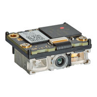
Opticon MDI-4100 Serial Interface Manual (139 pages)
Low Profile, High-Performance, 2D Imager Engine
Brand:
Opticon
| Category:
Barcode Reader
| Size: 3.99 MB
Table of Contents
Table of Contents
5
1 Overview
13
MDI-4000 Series Scan Engine Features
13
Integration Flow
14
2 About the MDI-4000 Series Scan Engines
15
Model Details
15
Standard Product Description
15
Model Name Description
16
Scan Area
16
Figure 1: Scan Area
16
Optional MEK-3100 Evaluation Board Accessory
17
Figure 2: Correct and Incorrect LED Aiming
17
3 Configuration
18
How to Configure the Scan Engine with Commands
18
Command Packet
18
Figure 3: MEK-3100 Evaluation Board
18
Figure 4: MEK-3100 Evaluation Board Kit
18
Sending Command Packets
19
Figure 5: Opticon's "Universal Config
19
Precautions for Sending Command Packets
21
Figure 6: Precautions for Sending Command Packets
21
Factory Default Settings
22
Save Settings
22
Custom Settings
23
How to Permanently Change the Factory Default Settings
23
Fast Boot Mode
23
Basic Commands
25
Trigger Command
25
Figure 7: Transition Diagram in Fast Boot Mode
25
Diagnostic Commands
26
ACK/NAK for Serial Commands
26
Reboot the Scan Engine
26
Enable/Disable 2D Menu Barcodes
27
Enable/Disable 1D Menu Barcodes
27
Mirrored Image
27
Figure 8: Mirrored Image Styles
28
Figure 9: Mirrored Image Configurations
28
Reading Operation
29
Buzzer and Indicator
29
Direct Numerical Input
29
How to Configure the Scan Engine with a 1D Menu Barcode
29
How to Configure the Scan Engine with a 2D Menu Barcode
30
Figure 10: Creating 1D Menu Barcodes with Opticon's "Universalconfig
30
Forced Initialization
31
4 Interface
31
Uart
31
Figure 11: Creating a 2D Menu Barcode with Opticon's "Universalconfig
31
How to Switch to UART from USB
32
UART Interface Signal
32
Baud Rate (Transfer Speed)
33
Character Format
33
Figure 12: Data Character Transfer Format
33
UART Basic Information
33
Figure 13: no Handshake
34
Handshaking (Flow Control)
34
Figure 14: BUSY/READY
35
Figure 15: RTS/CTS Data Transmission
35
Figure 16: CTS, Txd Signal Timing
35
Figure 17: Modem RTS/CTS Data Transmission
36
Figure 18: ACK/NAK Transmission
37
Figure 19: ACK/NAK Flowchart
37
Figure 20: ACK/NAK no Response Flowchart
38
Inter Character Delay (UART)
38
Troubleshooting UART
39
Usb-Com
39
How to Switch to USB-COM
39
USB-COM Interface Signal
40
USB-COM Basic Information
41
Integration (USB Driver)
41
Connection Confirmation (USB-COM)
41
Fixed USB-COM Port
42
Connection Method
42
COM to HID Output (WIME)
42
Troubleshooting USB-COM
43
Usb-Hid
43
Figure 21: COM to HID Output through WIME
43
How to Switch to USB-HID
44
USB-HID Interface Signal
44
Connection Confirmation (USB-HID)
45
USB-HID Basic Information
45
Data Output Speed (USB-HID)
46
Numlock Control and Capslock Control
46
Inter Character Delay (USB-HID)
47
Keyboard Language
47
Troubleshooting USB-HID
48
Data Buffer Mode Common Setting
48
5 Power Management and Timing
49
Power Mode Transition
49
Figure 22: Power Mode Transition
49
Current Consumption
50
Absolute Maximum Ratings
50
Recommended Operating Conditions
50
Peak Current Consumption
50
Current Consumption of the MDI-4X00
51
Current Consumption of the MDI-4X50
52
Low Power
53
Enable/Disable Low Power Mode
53
Transition Time
53
Figure 23: Transition Time
53
USB Low Power Mode Transition Condition
54
USB Selective Suspend
54
USB Low Power Mode Communication Sequence
54
How to Recover from Low Power Mode
55
Recover from Low Power Mode by Signal (UART)
55
Figure 24: USB Low Power Mode Communication Sequence
55
Figure 25: Recovery Example Using Trign Signal
56
Recover from Low Power Mode by Command (UART)
57
Figure 26: Recovery Example Using Commands
57
Recover from Low Power Mode (USB)
58
Figure 27: Recovery Example from Low Power Mode (USB)
58
Power on /OFF Timing
59
Power-On Timing
59
Power-Off Timing
59
Figure 28: Power-On Timing
59
Read Timing
60
Figure 29: Power-Off Timing
60
Figure 30: Read Timing
60
Figure 31: Trigger Signal Control
61
Read Time
61
Trigger Signal Control
61
Command Trigger Control
62
Figure 32: Start from Trign Signal End
62
Figure 33: Start from Trign Signal Start
62
Figure 34: Command Trigger Control
62
Figure 35: Command Trigger Control with Effective Read Time
62
Trigger Delay
63
6 Barcode Options
63
How to Set Readable Barcodes
63
Barcodes
63
Figure 36: Trigger Delay Timing
63
Postal Code
64
GS1 Databar
65
GS1 Composite Code
65
Setting Code Common Options
67
GS1 Conversion
67
Figure 37: GS1 Edit Feature in Opticon's "Universalconfig
68
Positive and Negative Image of Barcodes (1D Code Common)
69
Quiet Zone (1D Code Common)
69
Figure 38: Positive and Negative Barcode Images
69
Figure 39: Quiet Zone
69
Redundancy (1D Code Common)
70
Add-On Waiting Time
70
ECI Protocol Output
71
Optical Character Recognition
71
How to Set Code-Specific Options
72
Upc
72
Ean/Jan
76
Code 39 and Italian Pharmaceutical
80
Codabar
82
Interleaved 2 of 5 and S-Code
83
Code 128
84
Iata
85
Msi/Plessey
86
Plessey
86
Telepen
86
Code 11
86
Korean Postal Authority
87
GS1 Databar
87
GS1 Composite
88
Pdf417
90
QR Code
91
Data Matrix
92
Aztec Code
93
How to Set the Number of Characters to Read
95
Fixed Length ON, Minimum/Maximum Length for Selected Codes
95
Command List: Fixed Length On/Minimum/Maximum Length
96
7 Data String Options
96
How to Change Uppercase and Lowercase Letters
96
How to Add Characters
97
How to Set the Prefix/Suffix
97
Prefix/Suffix Commands
97
Figure 40: Prefix/Suffix and Preamble/Postamble
97
Prefix/Suffix Value Commands
99
Figure 41: Code Coordinates
102
8 Read Options
103
Read Modes
103
Single and Multiple Read Modes
103
Figure 42: Scan Time
103
Central Reading
104
Manual Trigger/Trigger Repeat
105
Figure 43: Readable Positions in Central Reading
105
Figure 44: Unreadable Positions in Central Reading
105
Auto Trigger
106
Auto Trigger Modes
106
Auto Trigger Sensitivity
107
Double Read Reset Time
107
Read Time Adjustment
107
Auto Trigger Sleep Mode
107
Detection Mode
108
Illumination and Aiming
108
Reading LED Illumination
108
External LED Illumination
109
LED Aiming
109
Batch Reading
109
9 Indicator Options
110
Buzzer
110
Buzzer Volume
110
Good Read Buzzer
111
Startup Buzzer
111
Read Timeout Buzzer
111
Intermediate Buzzer
112
Idle Level of Buzzern Pin
112
Good Read LED
112
Good Read LED Duration
112
Inverted Good Read LED
113
Good Read Aiming
113
General Indicator Timing
113
10 Appendix
114
Code ID Table
114
Opticon Code ID Prefix/Suffix Value
114
Code Option AIM/ISO15424 Code ID Prefix/Suffix Value
115
MDI-4Xx0 Specification Overview
120
Common Specification Overview
120
Technical Specifications
121
MDI-4Xx0 Detailed View
125
Figure 45: MDI-4100 and MDI-4150 Mechanical Drawing
125
Figure 46: MDI-4100 and MDI-4150 Circuit Board
126
Figure 47: MDI-4000 and MDI-4050 Mechanical Drawing
127
Figure 48: DBM-4000 and DBM-4050 Decoder Board
128
Figure 49: DBM-4000 and DBM-4050 Circuit Board
128
Sample Barcodes
129
Barcodes
129
Figure 50: FPC Cable
129
Postal Code
132
GS1 Databar
134
GS1 Composite Code
135
Barcodes
137
OCR Font (Machine Readable Travel Document)
138
OCR Font (Free OCR Edit)
139
Advertisement
Advertisement
Related Products
Opticon MDI-4000 Series
Opticon MDI-4050
Opticon MDI-4150
Opticon MDI-2300
Opticon MDI 1000
Opticon MDI-4 00/N210 Series
Opticon MDL-1000
Opticon MDL-2000
Opticon M-10
Opticon miniRITE
Opticon Categories
Barcode Reader
Scanner
Handhelds
Touch terminals
Cell Phone
More Opticon Manuals
Login
Sign In
OR
Sign in with Facebook
Sign in with Google
Upload manual
Upload from disk
Upload from URL