Sign In
Upload
Manuals
Brands
Omron Manuals
Controller
NJ501-4500
Omron NJ501-4500 Manuals
Manuals and User Guides for Omron NJ501-4500. We have
2
Omron NJ501-4500 manuals available for free PDF download: User Manual, Manual
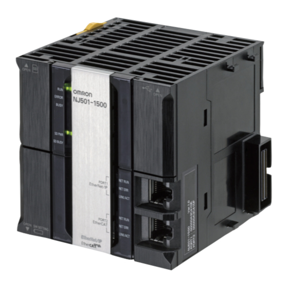
Omron NJ501-4500 User Manual (400 pages)
NJ-series CPU Unit Hardware
Brand:
Omron
| Category:
Control Unit
| Size: 7.58 MB
Table of Contents
Introduction
3
Relevant Manuals
4
Manual Structure
5
Sections in this Manual
7
Table of Contents
8
Terms and Conditions Agreement
12
Safety Precautions
14
Precautions for Safe Use
19
Precautions for Correct Use
29
Regulations and Standards
33
Versions
35
Related Manuals
38
Terminology
40
Revision History
45
Introduction to NJ-Series Controllers
47
Section 1 Introduction to NJ-Series Controllers
48
The NJ-Series Controllers
48
Features
48
Introduction to the System Configurations
50
Specifications
53
Overall Operating Procedure for the NJ-Series Controller
57
Overall Procedure
57
Procedure Details
58
System Configuration
63
Section 2 System Configuration
64
Basic System Configuration
64
Ethercat Network Configuration
66
CJ-Series Unit Configuration
67
Connecting to the Sysmac Studio
81
Network Configuration
82
Configuration Units
85
Section 3 Configuration Units
86
CPU Units
86
Models and Specifications
86
Components and Functions
87
SD Memory Cards
94
Models and Specifications
94
Purpose
94
Installing and Removing
96
Power Supply Units
98
Models and Specifications
98
Components and Functions
100
Selecting a Power Supply Unit
101
CJ-Series Basic I/O Units
106
Models and Specifications
106
Part Names and Functions
107
B7A Interface Ports
110
Overview
110
System Configuration
110
Models
110
B7A Communications Specifications
111
Common Specifications
112
B7A Interface Port I/O Types
112
Parts and Names
113
Transmission Error Processing
115
CJ-Series I/O Control Units and I/O Interface Units
116
Models and Specifications
116
Component and Functions
116
Sysmac Studio
117
Model Numbers
117
Connection
118
Installation and Wiring
121
Processing at Power on and Power off
122
Power on Operation
122
Power off Operation
123
Resetting the Controller from the Sysmac Studio
125
Fail-Safe Circuits
126
Order of Powering up the Controller and Controlled System
127
Mounting Units
129
Installation in a Control Panel
129
Connecting Controller Components
134
DIN Track Installation
136
Connecting CJ-Series Expansion Racks
139
Assembled Appearance and Dimensions
141
Wiring
146
Power Supply Wiring
146
Wiring the Built-In Ethercat Port
151
Wiring CJ-Series Basic I/O Units with Terminal Blocks
151
Wiring CJ-Series Basic I/O Units with Connectors
153
Connecting to Connector-Terminal Block Conversion Units or I/O Relay Terminals
158
Connecting I/O Devices
159
Input Devices
159
Wiring the Built-In Ethercat Port
162
Wiring B7A Interface Units
163
Connection Diagrams
167
Control Panel Installation
169
Temperature
169
Humidity
171
Vibration and Shock
171
Atmosphere
171
Electrical Environment
172
Grounding
176
Troubleshooting
181
Operation after an Error
182
Overview of NJ-Series Status
182
Fatal Errors in the CPU Unit
183
Non-Fatal Error in CPU Unit
184
Troubleshooting
191
Checking to See if the CPU Unit Is Operating
191
Troubleshooting Flowchart for Non-Fatal Errors
192
Error Table
193
Error Descriptions
210
Troubleshooting Errors that Are Not in the CPU Unit
274
Inspection and Maintenance
277
Section 6 Inspection and Maintenance
278
Periodic Maintenance and Inspection
278
Periodic Inspection
278
Unit Replacement Precautions
279
Required Tools
279
Replacing the Battery
280
Battery Replacement
280
Operation Without a Battery
283
Appendices
285
Specifications
286
Specifications of Basic I/O Units
287
A-2-1 Overview of Units
287
Basic I/O Units
289
A-2-3 Precautions on Contact Output Units
336
Connecting Connector-Terminal Block Conversion Units and I/O Relay Terminals
338
Dimensions
373
A-3-1 NJ-Series CPU Units
373
A-3-2 NJ-Series Power Supply Units
374
A-3-3 CJ-Series Basic I/O Units
375
A-3-4 B7A Interface Unit
378
A-3-5 CJ-Series I/O Control Unit and I/O Interface Unit
378
A-3-6 SD Memory Card
378
Load Short-Circuit Protection and Line Disconnection Detection for CJ-Series Basic I/O Units
379
A-4-1 Load Short-Circuit Protection and Line Disconnection Detection for CJ1W-OD202
379
A-4-2 Load Short-Circuit Protection for CJ1W-OD204/OD212/OD232/MD232
382
EMC Directive Measures for Relay Outputs
384
System-Defined Variables Related to Hardware
386
Version Information
387
Relationship between Unit Versions of CPU Units and Sysmac Studio Versions
387
A-7-2 Relationship between Hardware Revisions of CPU Units and Sysmac Studio Versions
389
A-7-3 Functions that Were Added or Changed for each Unit Version
390
A-7-4 Performance Improvements for Unit Version Upgrades
393
Advertisement
Omron NJ501-4500 Manual (336 pages)
NJ-series NJ Robotics CPU Unit
Brand:
Omron
| Category:
Controller
| Size: 16.16 MB
Table of Contents
Introduction
3
Intended Audience
3
Applicable Products
3
Relevant Manuals
4
Manual Structure
6
Page Structure and Symbols
6
Special Information
7
Precaution on Terminology
8
Sections in this Manual
9
Table of Contents
10
Contents
11
Terms and Conditions Agreement
14
Warranty, Limitations of Liability
14
Application Considerations
15
Disclaimers
15
Safety Precautions
16
Definition of Precautionary Information
16
Symbols
16
Warnings
17
Cautions
19
Precautions for Safe Use
21
Precautions for Correct Use
28
Regulations and Standards
30
Using Product Outside Japan
30
Conformance to EC Directives
30
Conformance to Shipbuilding Standards
31
Using Controllers in Robot Systems
31
Software Licenses and Copyrights
31
Versions
32
Confirming Versions
32
Related Manuals
35
Terminology
37
Revision History
39
Overview of NJ Robotics CPU Unit
41
Section 1 Overview of NJ Robotics CPU Unit
42
Features and System Configuration of Unit
42
Features of NJ Robotics CPU Unit
42
Introduction to the System Configurations
44
Operation Procedure of Unit
47
Specifications of Unit
48
Performance Specifications
48
Function Specifications
48
Robot Control Configuration
50
Features of NJ Robotics CPU Unit
51
Controllable Robot Types
52
Coordinate System
55
Overview of Coordinate Systems
55
Coordinate Systems
64
Robot Functions
65
Kinematics Setting
65
Workspace Check
73
User Coordinate System (UCS)
79
Monitoring
80
Time-Specified Absolute Positioning
80
Conveyor Synchronization
81
Inverse Kinematics
82
Robot Tool
82
Robot Jogging
84
Acceleration/Deceleration
85
Checking Maximum Interpolation Velocity and Maximum Interpolation Acceleration/Deceleration
85
2-3-11 Multi-Execution of Instructions with Buffered Mode
87
2-3-12 Multi-Execution of Instructions with Blending Mode
87
2-3-13 Trajectory Types for Time-Specified Motion
88
Setting Robot Functions
91
Setting Group for Robot
92
Group Setting Procedures
92
Axes Group Settings
93
Axis Settings
94
Robot Kinematics Settings
99
Homing
100
Target Position and Direction Setting Method
101
Position Settings
101
Rotational Axis Control
101
Checking Wiring from the Sysmac Studio
104
Robot Instructions
105
Overview of Robot Instructions
106
List of Robot Instructions
106
Axes Group Instructions Enabled/Disabled
106
Robot Execution and Stop Instructions
107
Unusable Output Variables of Axes Group
108
Details on Robot Instructions
109
Mc_Setkintransform
110
Mc_Definecoordsystem
119
Mc_Definetooltransform
123
Mc_Groupmon
127
Mc_Movetimeabsolute
133
Mc_Synclinearconveyor
142
Mc_Syncout
163
Mc_Inversekin
172
Mc_Robotjog
177
Mc_Groupsyncmoveabsolute
186
Multi-Execution of Motion Control Instructions
188
Multi-Execution in Aborting Mode
188
Multi-Execution in Buffered Mode
189
Multi-Execution in Blending Mode
190
State Transitions of Robot Instructions
195
Sample Programming
196
Vision & Robot Integrated Simulation
199
Section 5 Vision & Robot Integrated Simulation
200
Overview of Simulation
200
Models that Support Simulation
201
Simulation Procedures
203
Troubleshooting
205
Section 6 Troubleshooting
206
Error Table
206
Error Description
226
Interpreting Error Description
226
Error Descriptions
227
Appendices
309
Sysmac Studio Robot Additional Option
310
A-1-1 Enabling the Sysmac Studio Robot Additional Option
310
Enabling the Sysmac Studio Robot Additional Option
310
A-1-2 Disabling the Sysmac Studio Robot Additional Option
312
A-1-3 3D Equipment Model Creation Wizard
314
A-1-4 3D Machine Models
316
A-1-5 Calculation of Calibration Parameters
327
A-1-6 Display of Images in 3D Motion Monitoring
328
A-2 Sysmac Studio Robot Options
329
Enabling Sysmac Studio Robot Options
329
A-2-2 Disabling Sysmac Studio Robot Options
331
Advertisement
Related Products
Omron NJ501-4400
Omron NJ501-4320
Omron NJ501-4310
Omron NJ501-4300
Omron NJ501-*4 Series
Omron NJ501-1300
Omron NJ501-1500
Omron NJ501 series
Omron NJ501-*5 Series
Omron NJ501-14 Series
Omron Categories
Blood Pressure Monitor
Controller
Accessories
Switch
Inverter
More Omron Manuals
Login
Sign In
OR
Sign in with Facebook
Sign in with Google
Upload manual
Upload from disk
Upload from URL