Sign In
Upload
Manuals
Brands
Nortel Manuals
Network Router
1000ASE-XD
Nortel 1000ASE-XD Manuals
Manuals and User Guides for Nortel 1000ASE-XD. We have
1
Nortel 1000ASE-XD manual available for free PDF download: Using Manual
Nortel 1000ASE-XD Using Manual (214 pages)
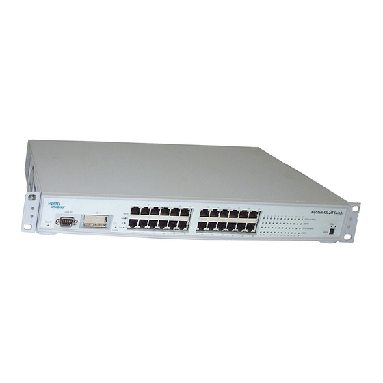
10/100/1000 Switch
Brand:
Nortel
| Category:
Network Router
| Size: 11.68 MB
Table of Contents
Restricted Rights Legend
2
Statement of Conditions
2
Table of Contents
7
Before You Begin
19
Preface
19
Text Conventions
20
Related Publications
22
How to Get Help
23
Chapter 1 Baystack 420 Switch
25
Physical Description
25
Figure 1 Baystack 420 Switch
25
Front Panel
26
Console Port
26
Figure 2 Baystack 420 Switch Front Panel
26
Table 1 Components on the Baystack 420 Switch Front Panel
26
Gigabit Interface Converter (GBIC)
27
Port Connectors
27
Figure 3 Baystack 420 Switch LED Display Panel
28
LED Display Panel
28
Table 2 Baystack 420 Switch LED Descriptions
29
Back Panel
30
Cascade up and down Connectors
30
Cooling Fans
30
Figure 4 Baystack 420 Switch Back Panel
30
Table 3 Components on the Baystack 420 Switch Back Panel
30
AC Power Receptacle
31
Table 4 International Power Cord Specifications
31
Features
34
Virtual Local Area Networks (Vlans)
34
Security
35
Figure 5 Baystack 420 Switch Security Feature
35
MAC Address-Based Security
37
RADIUS-Based Network Security
37
Flash Memory Storage
38
Configuration Parameters Storage
38
Switch Software Image Storage
38
Multilink Trunking
39
Port Mirroring (Conversation Steering)
39
Autosensing, Autonegotiation, and Autopolarity
39
Rfcs
40
Standards
40
SNMP MIB Support
41
Table 5 SNMP MIB Support
41
SNMP Trap Support
42
Bootp Automatic IP Configuration/Mac Address
42
Table 6 Support SNMP Traps
42
Configuration and Switch Management
43
Network Configuration
45
Network Configuration Examples
45
Desktop Switch Application
45
Segment Switch Application
46
Figure 6 Baystack 420 Switch Used as a Desktop Switch
46
Figure 7 Baystack 420 Switch Used as a Segment Switch
47
Chapter 2 Network Configuration
47
High-Density Switched Workgroup Application
48
Baystack 420 Switch Stack Operation
49
Unit Select Switch
49
Figure 8 Configuring Power Workgroups and a Shared Media Hub
49
Base Unit
50
Initial Installation
50
Stack MAC Address
50
Removing a Unit from the Stack
51
Stack Configurations
51
Stack up Configurations
51
Figure 9 Stack up Configuration Example
52
Stack down Configurations
52
Table 7 Stack up Configuration Description
52
Figure 10 Stack down Configuration Example
53
Table 8 Stack down Configuration Description
53
IEEE 802.1Q VLAN Workgroups
54
IEEE 802.1Q Tagging
55
Figure 11 Port-Based VLAN Example
55
Figure 12 Default VLAN Settings
57
Figure 13 Port-Based VLAN Assignment
58
Figure 14 802.1Q Tagging (after Port-Based VLAN Assignment)
58
Figure 15 802.1Q Tag Assignment
59
Figure 16 802.1Q Tagging (after 802.1Q Tag Assignment)
59
Vlans Spanning Multiple Switches
60
Figure 17 Vlans Spanning Multiple 802.1Q Tagged Switches
60
Vlans Spanning Multiple 802.1Q Tagged Switches
60
Figure 18 Vlans Spanning Multiple Untagged Switches
61
VLANS Spanning Multiple Untagged Switches
61
Figure 19 Possible Problems with Vlans and Spanning Tree Protocol
62
Shared Servers
63
Figure 20 Multiple Vlans Sharing Resources
63
Figure 21 VLAN Broadcast Domains Within the Switch
64
Figure 22 Default VLAN Configuration Screen Example
65
Figure 23 VLAN Configuration Screen Example
66
Figure 24 Default VLAN Port Configuration Screen Example
67
VLAN Workgroup Summary
68
Figure 25 VLAN Port Configuration Screen Example
68
Figure 26 VLAN Configuration Spanning Multiple Switches
69
VLAN Configuration Rules
70
Multilink Trunks
70
Figure 27 Switch-To-Switch Trunk Configuration Example
71
Client/Server Configuration Using Multilink Trunks
72
Figure 28 Switch-To-Server Trunk Configuration Example
72
Trunk Configuration Screen Examples
73
Figure 29 Client/Server Configuration Example
73
Figure 30 Choosing the Multilink Trunk Configuration Menu Screen
74
Trunk Configuration Screen for Switch S1
74
Figure 31 Multilink Trunk Configuration Screen for Switch S1
75
Trunk Configuration Screen for Switch S2
76
Figure 32 Multilink Trunk Configuration Screen for Switch S2
77
Figure 33 Multilink Trunk Configuration Screen for Switch S3
78
Trunk Configuration Screen for Switch S3
78
Trunk Configuration Screen for Switch S4
79
Figure 34 Multilink Trunk Configuration Screen for Switch S4
80
Before You Configure Trunks
81
Figure 35 Path Cost Arbitration Example
82
Spanning Tree Considerations for Multilink Trunks
82
Figure 36 Example 1: Correctly Configured Trunk
83
Figure 37 Example 2: Detecting a Misconfigured Port
84
Additional Tips about the Multilink Trunking Feature
85
Port Mirroring
85
Figure 38 Port Mirroring Configuration Port-Based Screen Example
86
Chapter 3 Using the Console Interface
87
Accessing the CI Menus and Screens
87
Using the CI Menus and Screens
88
Navigating the CI Menus and Screens
88
Screen Fields and Descriptions
89
Figure 39 Map of Console Interface Screens
89
Main Menu
90
Figure 40 Console Interface Main Menu
91
Table 9 Console Interface Main Menu Options
91
Figure 41 IP Configuration/Setup Screen
94
Table 10 IP Configuration/Setup Screen Fields
95
Choosing a Bootp Request Mode
96
Bootp Always
97
Bootp When Needed
97
Bootp Disabled
98
Bootp or Last Address
98
IP Configuration/Setup Screen
94
Figure 42 SNMP Configuration Screen
99
SNMP Configuration Screen
99
Table 11 SNMP Configuration Screen Fields
99
System Characteristics Screen
100
Figure 43 System Characteristics Screen
101
Table 12 System Characteristics Screen Fields
101
Figure 44 Switch Configuration Menu Screen
103
Switch Configuration Menu Screen
103
Table 13 Switch Configuration Menu Options
104
MAC Address Table Screen
105
Figure 45 MAC Address Table Screen
106
Table 14 MAC Address Table Screen Fields
106
Figure 46 MAC Address Security Configuration Menu Screen
107
MAC Address Security Configuration Menu Screen
107
Table 15 MAC Address Security Configuration Menu Options
108
Figure 47 MAC Address Security Configuration Screen
109
Table 16 MAC Address Security Configuration Screen Fields
109
MAC Address Security Port Configuration Screen
111
Figure 48 MAC Security Port Configuration Screen (1 of 2)
112
Figure 49 MAC Security Port Configuration Screen (2 of 2)
112
MAC Address Security Port Lists Screens
113
Table 17 MAC Security Port Configuration Screen Fields
113
Configuration Menu
114
Figure 50 MAC Address Security Port Lists Screens
114
More Information
114
Port List Syntax
115
Table 18 MAC Address Security Port Lists Screen Fields
115
Accelerator Keys for Repetitive Tasks
116
Figure 52 MAC Address Security Table Screens
118
MAC Address Security Table Screens
118
Table 19 MAC Address Security Table Screen Fields
119
VLAN Configuration Menu Screen
120
Figure 54 VLAN Configuration Menu Screen
121
Table 20 VLAN Configuration Menu Options
121
VLAN Configuration Screen
122
Figure 55 VLAN Configuration Screen
123
Table 21 VLAN Configuration Screen Fields
123
VLAN Port Configuration Screen
125
Figure 56 VLAN Port Configuration Screen
126
Table 22 VLAN Port Configuration Screen Fields
126
VLAN Display by Port Screen
127
Figure 57 VLAN Display by Port Screen
128
Table 23 VLAN Display by Port Screen Fields
128
Figure 58 Port Configuration Screen (1 of 2)
129
Port Configuration Screen
129
Figure 59 Port Configuration Screen (2 of 2)
130
Table 24 Port Configuration Screen Fields
130
High Speed Flow Control Configuration Screen
131
Figure 60 High Speed Flow Control Configuration
132
Table 25 High Speed Flow Control Configuration Screen Fields
132
Choosing a High Speed Flow Control Mode
133
Asymmetric Mode
133
Symmetric Mode
133
Multilink Trunk Configuration Menu Screen
133
Figure 61 Multilink Trunk Configuration Menu Screen
134
Multilink Trunk Configuration Screen
135
Table 26 Multilink Trunk Configuration Menu Options
135
Figure 62 Multilink Trunk Configuration Screen
136
Table 27 Multilink Trunk Configuration Screen Fields
136
Multilink Trunk Utilization Screen
137
Figure 63 Multilink Trunk Utilization Screen (1 of 2)
138
Figure 64 Multilink Trunk Utilization Screen (2 of 2)
138
Port Mirroring Configuration Screen
139
Table 28 Multilink Trunk Utilization Screen Fields
139
Figure 65 Port Mirroring Configuration Screen
140
Table 29 Port Mirroring Configuration Screen Fields
140
Port Statistics Screen
141
Table 30 Monitoring Modes
141
Figure 66 Port Statistics Screen
142
Table 31 Port Statistics Screen Fields
143
System Log Screen
145
Figure 67 System Log Screen
146
Table 32 System Log Screen Fields
146
Console/Comm Port Configuration Screen
147
Figure 68 Console/Comm Port Configuration Screen
148
Table 33 Console/Comm Port Configuration Screen Fields
148
Figure 69 Renumber Stack Units Screen
154
Renumber Stack Units Screen
154
Hardware Unit Information Screen
155
Table 34 Renumber Stack Units Screen Fields
155
Figure 70 Hardware Unit Information Screen
156
Spanning Tree Configuration Menu Screen
156
Figure 71 Spanning Tree Configuration Menu Screen
157
Table 35 Spanning Tree Configuration Menu Options
157
Figure 72 Spanning Tree Port Configuration Screen (1 of 2)
158
Spanning Tree Port Configuration Screen
158
Figure 73 Spanning Tree Port Configuration Screen (2 of 2)
159
Table 36 Spanning Tree Port Configuration Screen Fields
159
Figure 74 Spanning Tree Switch Settings Screen
161
Spanning Tree Switch Settings Screen
161
Table 37 Spanning Tree Switch Settings Parameters
162
Figure 75 TELNET Configuration Screen
164
TELNET Configuration Screen
164
Table 38 TELNET Configuration Screen Fields
165
Software Download Screen
166
Figure 76 Software Download Screen for a Baystack 420 Switch Stack
168
Table 39 Software Download Screen Fields
168
LED Indications During the Download Process
169
Configuration File Download/Upload Screen
169
Figure 77 Configuration File Download/Upload Screen
170
Table 40 Configuration File Download/Upload Screen Fields
171
Requirements
172
Table 41 Parameters Not Saved to the Configuration File
172
Chapter 4 Troubleshooting
173
Interpreting the Leds
173
Figure 78 LED Display Panel
174
Table 42 Baystack 420 Switch LED Descriptions
174
Diagnosing and Correcting Problems
175
Normal Power-Up Sequence
176
Table 43 Corrective Actions
176
Port Connection Problems
177
Autonegotiation Modes
177
Port Interface
178
Appendix A Technical Specifications
179
Electrical
179
Environmental
179
Table 44 Environmental Specifications
179
Table 45 Electrical Parameters
179
Performance Specifications
180
Physical Dimensions
180
Table 46 Physical Dimensions
180
Table 47 Performance Specifications
180
Electromagnetic Emissions
181
Network Protocol and Standards Compatibility
181
Safety Agency Certification
181
Electromagnetic Immunity
182
Appendix B Installing a Gigabit Interface Converter (GBIC)
183
Product Description
183
GBIC Labeling
184
Figure 79 Types of Gbics
184
Figure 80 Nortel Label on a GBIC
184
GBIC Models
185
GBIC Specifications
185
Standards, Connectors, Cabling, and Distance
185
1000Base-Sx
185
Table 48 Nortel Networks GBIC Models
185
Table 49 GBIC Specifications
185
1000Base-Lx
186
Table 50 Model 1000BASE-SX GBIC Specifications
186
Table 51 Model 1000BASE-LX GBIC Specifications
187
1000Base-XD
188
Table 52 Model 1000ASE-XD GBIC Specifications
188
1000Base-Zx
189
Table 53 Model 1000BASE-ZX GBIC Specifications
189
Handling, Safety, and Environmental Guidelines
190
Installing a Gbic
191
Figure 81 Installing a GBIC
192
Figure 82 Removing a GBIC
192
Appendix C
193
Quick Configuration for Multilink Trunking
193
Figure 83 Configuring Multilink Trunks
194
Appendix D Connectors and Pin Assignments
195
Figure 84 RJ-45 (8-Pin Modular) Port Connector
195
RJ-45 (10BASE-T/100BASE-TX) Port Connectors
195
MDI and MDI-X Devices
196
Table 54 RJ-45 Port Connector Pin Assignments
196
Figure 85 MDI-X to MDI Cable Connections
197
MDI-X to MDI Cable Connections
197
MDI-X to MDI-X Cable Connections
197
DB-9 (RS-232-D) Console/Comm Port Connector
198
Figure 86 MDI-X to MDI-X Cable Connections
198
Figure 87 DB-9 Console Port Connector
198
Table 55 DB-9 Console Port Connector Pin Assignments
199
Appendix E
201
Default Settings
201
Table 56 Factory Default Settings
201
Figure 51 MAC Address Security Port Lists Screen
202
Figure 53 MAC Address Security Table Screen
202
Appendix F
207
Sample Bootp Configuration File
207
Index
209
Advertisement
Advertisement
Related Products
Nortel 114200-E
Nortel 10292FA
Nortel 10396EA
Nortel 1500 Series
Nortel 1700
Nortel Contivity 1740
Nortel Contivity VPN Switch 1010
Nortel Accelar 1050
Nortel Contivity 110
Nortel 1000S
Nortel Categories
IP Phone
Telephone
Switch
Software
Server
More Nortel Manuals
Login
Sign In
OR
Sign in with Facebook
Sign in with Google
Upload manual
Upload from disk
Upload from URL