Sign In
Upload
Manuals
Brands
Mitsubishi Manuals
Robotics
MELFA RH-3FH-D Series
Mitsubishi MELFA RH-3FH-D Series Manuals
Manuals and User Guides for Mitsubishi MELFA RH-3FH-D Series. We have
1
Mitsubishi MELFA RH-3FH-D Series manual available for free PDF download: Special Specifications Manual
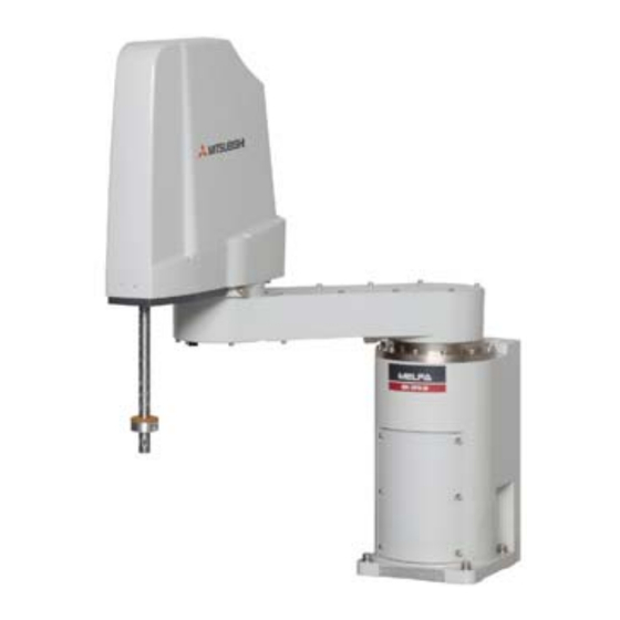
Mitsubishi MELFA RH-3FH-D Series Special Specifications Manual (188 pages)
Brand:
Mitsubishi
| Category:
Robotics
| Size: 6.36 MB
Table of Contents
Table of Contents
9
General Configuration
12
Structural Equipment
12
Standard Structural Equipment
12
Special Specifications
12
Options
12
Maintenance Parts
12
Model Type Name of Robot
13
How to Identify the Robot Model
13
Combination of the Robot Arm and the Controller
14
CE Marking Specifications
14
Indirect Export
14
Instruction Manuals
14
Contents of the Structural Equipment
15
Robot Arm
15
Controller
16
Contents of the Option Equipment and Special Specification
17
Robot Arm
20
Standard Specifications
20
Basic Specifications
20
Standard Specification
20
Clean Specification
22
The Counter-Force Applied to the Installation Surface
23
Definition of Specifications
24
Pose Repeatability
24
Rated Load (Mass Capacity)
25
Relationships Among Mass Capacity, Speed, and Acceleration/Deceleration Speed
26
Setting Load Capacity and Size (Hand Conditions)
26
Vibrations at the Tip of the Arm During Low-Speed Operation of the Robot
26
Vibration of Shaft (J3 Axis) Position and Arm End
27
Relationship between Mass Capacity and Speed
27
Relationship between Height of Shaft (J3 Axis) and Acceleration/Deceleration Speed
28
Relation between Offset Length and the Maximum Speed
29
Time to Reach the Position Repeatability
30
Collision Detection
30
Protection Specifications
31
Types of Protection Specifications
31
Clean Specifications
31
Types of Clean Specifications
31
Names of each Part of the Robot
33
Outside Dimensions ・ Operating Range Diagram
34
Standard Specification
34
Clean Specification
40
Mechanical Interface and Installation Surface
46
Change the Operating Range
47
Operating Range Changeable Angle
47
The Change Method of the Operating Range
48
Tooling
49
Wiring and Piping for Hand
49
Internal Air Piping
50
Standard Type
50
Clean Type
50
Internal Wiring for the Hand Output Cable
50
Internal Wiring for the Hand Input Cable
50
Ethernet Cable
50
About the Installation of Tooling Wiring and Piping (Examples of Wiring and Piping)
51
Example of Wiring and Piping <1
52
Wiring and Piping Example <2
53
Precautions for the Clean Specification
53
Wiring and Piping System Diagram for Hand
54
Electrical Specifications of Hand Input/Output
56
Air Supply Circuit Example for the Hand
57
Shipping Special Specifications, Options, and Maintenance Parts
58
Shipping Special Specifications
58
Machine Cable
59
Options
60
Machine Cable Extension
61
Changes J1 Axis Operating Range
65
Solenoid Valve Set
66
Hand Input Cable
68
Hand Output Cable
69
Hand Curl Tube
70
Internal Wiring/Piping Set for Hand
71
External Wiring/Piping Box
72
About Overhaul
74
Maintenance Parts
75
Controller
76
Standard Specifications
76
Protection Specifications and Operating Supply
77
Names of each Part
78
Controller
78
CR750 Controller
78
CR751 Controller
80
Outside Dimensions/Installation Dimensions
82
Outside Dimensions
82
CR750 Controller
82
CR751 Controller
83
Installation Dimensions
84
CR750 Controller
84
CR751 Controller
86
External Input/Output
88
Types
88
Dedicated Input/Output
89
Emergency Stop Input and Output Etc
92
Connection of the External Emergency Stop
92
CR751 Controller
98
CR750 Controller
101
Enabling Device Function
103
When Door Is Opening
103
When Door Is Closing
104
Automatic Operation/Jog Operation/Brake Release and Necessary Switch Settings
104
Mode Changeover Switch Input
105
Specification of the Key Switch Interface
105
Connection of the Mode Changeover Switch Input
106
Additional Axis Function
107
Wiring of the Additional Axis Interface
107
CR750 Controller
107
CR751 Controller
108
Magnet Contactor Control Connector Output (AXMC) for Addition Axes
111
CR750 Controller
112
CR751 Controller
113
Options
114
Teaching pendant (T/B)
115
Parallel I/O Interface
118
External I/O Cable
123
Parallel I/O Unit
125
External I/O Cable
136
CC-Link Interface
138
RT Toolbox2/Rt Toolbox2 Mini
142
Instruction Manual(Bookbinding)
143
Maintenance Parts
144
Software
145
List of Commands
145
List of Parameters
148
Instruction Manual
150
The Details of each Instruction Manuals
150
Safety
151
Self-Diagnosis Stop Functions
151
External Input/Output Signals that Can be Used for Safety Protection Measures
152
Precautions for Using Robot
152
Safety Measures for Automatic Operation
153
Safety Measures for Teaching
153
Safety Measures for Maintenance and Inspections, Etc
153
Examples of Safety Measures
154
CR750 Controller
154
CR751 Controller
159
External Emergency Stop Connection [Supplementary Explanation]
164
Working Environment
167
Precautions for Handling
167
EMC Installation Guideline
169
Outlines
169
EMC Directive
169
EMC Measures
170
Component Parts for EMC Measures
170
Ferrite Core
170
Line Noise Filter
170
7Appendix
172
Appendix 1 : Specifications Discussion Material
172
Advertisement
Advertisement
Related Products
Mitsubishi MELFA RH-3SDHR3515
Mitsubishi MELFA RH-3SDHR3512C
Mitsubishi MELFA RH-3SDHR3512W
Mitsubishi RH-3FH Series
Mitsubishi RH-3SQHR3515
Mitsubishi RH-6FH Series
Mitsubishi RH-12FH Series
Mitsubishi RH-20FH Series
Mitsubishi MELFA RH-12SH Series
Mitsubishi MELFA RH-18SH Series
Mitsubishi Categories
Air Conditioner
Controller
Projector
Automobile
Engine
More Mitsubishi Manuals
Login
Sign In
OR
Sign in with Facebook
Sign in with Google
Upload manual
Upload from disk
Upload from URL