Sign In
Upload
Manuals
Brands
Mitsubishi Manuals
Control Unit
A1SD75M3
Mitsubishi A1SD75M3 Manuals
Manuals and User Guides for Mitsubishi A1SD75M3. We have
1
Mitsubishi A1SD75M3 manual available for free PDF download: User Manual
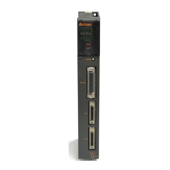
Mitsubishi A1SD75M3 User Manual (746 pages)
Positioning Module
Brand:
Mitsubishi
| Category:
Control Unit
| Size: 7.64 MB
Table of Contents
Safety Instructions
3
Revisions
6
Table of Contents
7
About Manuals
14
Conformation to the EMC Directive and Low Voltage Instruction
14
Using this Manual (1
15
Using this Manual (2
16
Using this Manual (3
17
Generic Terms and Abbreviations
18
Enclosed Parts
19
Product Outline
23
Positioning Control
24
Features of AD75
24
Purpose and Applications of Positioning Control
28
Mechanism of Positioning Control
30
Outline Design of Positioning System
32
Communicating Signals between AD75 and each Module
34
Flow of System Operation
36
Flow of All Processes
36
Outline of Starting
38
Outline of Stopping
40
Outline for Restarting
41
System Configuration
43
General Image of System
44
List of Configuration Devices
46
Applicable System
48
Precautions for Configuring System
49
Precautions for Mounting Base Unit
49
Precautions According to Module Version
49
Precautions for Using 3-Axis Module
50
Precautions for Configuring Absolute Position Detection System
50
Precautions for Machine Zero Point Return Control in Absolute Position Detection System
50
Precautions for Using Servo Amplifier MR-J2S-B, MR-J2-03B5
51
Specifications and Functions
53
General Specifications
54
Performance Specifications
55
List of Functions
56
AD75 Control Functions
56
AD75 Main Functions
58
AD75 Auxiliary Functions and Common Functions
60
Combination of AD75 Main Functions and Auxiliary Functions
62
Specifications of Input/Output Signals with PLC CPU
64
List of Input/Output Signals with PLC CPU
64
Details of Input Signals (AD75 PLC CPU)
65
Details of Output Signals (PLC CPU AD75)
66
Specifications of Interfaces with External Devices
67
Electrical Specifications of Input Signals
67
Signal Layout for External Device Connection Connector
68
List of Input Signal Details
69
Interface Internal Circuit
70
Installation, Wiring and Maintenance of the Product
71
Outline of Installation, Wiring and Maintenance
72
Installation, Wiring and Maintenance Procedures
72
Names of each Part
73
Handling Precautions
75
Installation
77
Precautions for Installation
77
Wiring
78
Precautions for Wiring
78
Wiring the External Device Connection Connector Pins
82
Confirming the Installation and Wiring
86
Items to Confirm When Installation and Wiring Are Completed
86
Single Module Test
87
Maintenance
90
Precautions for Maintenance
90
Disposal Instructions
90
Data Used for Positioning Control
92
Types of Data
92
Parameters and Data Required for Control
92
Setting Items for Positioning Parameters
94
Setting Items for Zero Point Return Parameters
96
Setting Items for Servo Parameters
97
Setting Items for Positioning Data
99
Setting Items for Start Block Data
101
Setting Items for Condition Data
102
Types and Roles of Monitor Data
103
Types and Roles of Control Data
107
List of Parameters
112
Basic Parameters 1
112
Basic Parameters 2
116
Detailed Parameters 1
118
Detailed Parameters 2
128
Zero Point Return Basic Parameters
137
Zero Point Return Detailed Parameters
144
Servo Parameters for MR-H-B (MR-H-BN)
148
Servo Parameters for MR-J-B
158
Servo Parameters for MR-J2-B
168
Servo Parameters for MR-J2S-B
178
Servo Parameters for MR-J2-03B5
194
List of Positioning Data
202
List of Start Block Data
217
List of Condition Data
221
List of Monitor Data
226
System Monitor Data
226
Axis Monitor Data
236
List of Control Data
258
System Control Data
258
Axis Control Data
264
Sequence Program Used for Positioning Control
277
Precautions for Creating Program
278
List of Devices Used
280
Creating a Program
284
General Configuration of Program
284
Positioning Control Operation Program
285
Positioning Program Examples
288
Program Details
297
Initialization Program
297
Start Details Setting Program
298
Start Program
299
Continuous Operation Interrupt Program
307
Restart Program
309
Stop Program
312
Memory Configuration and Data Process
315
Configuration and Roles of AD75 Memory
316
Buffer Memory Area Configuration
319
Data Transmission Process
320
Zero Point Return Control
335
Outline of Zero Point Return Control
336
Two Types of Zero Point Return Control
336
Machine Zero Point Return
338
Outline of the Machine Zero Point Return Operation
338
Machine Zero Point Return Method
339
Zero Point Return Method (1): Near-Point Dog Method
341
Zero Point Return Method (2): Near-Point Dog Method 2)
343
Zero Point Return Method (3): Count Method 1)
345
Zero Point Return Method (4): Count Method 2)
348
Zero Point Return Method (5): Count Method 3)
350
Zero Point Return Method (6): Data Setting Method
352
High-Speed Zero Point Return
353
Outline of the High-Speed Zero Point Return Operation
353
Positioning to the Zero Point
355
Main Positioning Control
359
Outline of Main Positioning Controls
360
Data Required for Main Positioning Control
361
Operation Patterns of Main Positioning Controls
362
Designating the Positioning Address
371
Confirming the Current Value
372
Control Unit "Degree" Handling
374
Interpolation Control
377
Setting the Positioning Data
380
Relation between each Control and Positioning Data
380
1-Axis Linear Control
381
2-Axis Linear Interpolation Control
383
1-Axis Fixed-Dimension Feed Control
387
2-Axis Fixed-Dimension Feed Control (Interpolation)
389
2-Axis Circular Interpolation Control with Auxiliary Point Designation
392
2-Axis Circular Interpolation Control with Center Point Designation
398
Speed Control
405
Speed/Position Changeover Control
408
Current Value Change
415
JUMP Command
420
Advanced Positioning Control
423
Outline of Advanced Positioning Control
424
Data Required for Advanced Positioning Control
425
Start Block Data" and "Condition Data" Configuration
426
Advanced Positioning Control Execution Procedure
428
Setting the Start Block Data
429
Relation between Various Controls and Start Block Data
429
Block Start (Normal Start)
430
Condition Start
432
Wait Start
433
Simultaneous Start
434
Stop
435
Repeated Start (for Loop)
436
Repeated Start (for Condition)
437
Restrictions When Using the NEXT Start
438
Setting the Condition Data
439
Relation between Various Controls and the Condition Data
439
Condition Data Setting Examples
441
Start Program for Advanced Positioning Control
442
Starting Advanced Positioning Control
442
Example of a Start Program for Advanced Positioning Control
443
Manual Control
447
Outline of Manual Control
448
Two Manual Control Methods
448
JOG Operation
450
Outline of JOG Operation
450
JOG Operation Execution Procedure
453
Setting the Required Parameters for JOG Operation
454
Creating Start Programs for JOG Operation
456
JOG Operation Example
459
Manual Pulse Generator Operation
463
Outline of Manual Pulse Generator Operation
463
Manual Pulse Generator Operation Execution Procedure
467
Setting the Required Parameters for Manual Pulse Generator Operation
468
Creating a Program to Enable/Disable the Manual Pulse Generator Operation
469
Control Auxiliary Functions
473
Outline of Auxiliary Functions
474
Auxiliary Functions Specifically for Machine Zero Point Returns
476
Zero Point Return Retry Function
476
Zero Point Shift Function
482
Functions for Compensating the Control
485
Backlash Compensation Function
485
Electronic Gear Function
487
Near Pass Mode Function
492
Follow up Processing Function
496
Functions to Limit the Control
497
Speed Limit Function
497
Torque Limit Function
499
Software Stroke Limit Function
502
Hardware Stroke Limit Function
508
Servo ON/OFF Function
510
Functions to Change the Control Details
515
Speed Change Function
515
Override Function
522
Acceleration/Deceleration Time Change Function
525
Torque Change Function
528
Absolute Position Restoration Function
530
Outline of Absolute Position Restoration Function
530
Absolute Position Restoration Mode Switching Function
537
Other Functions
542
Step Function
542
Skip Function
547
M Code Output Function
550
Teaching Function
554
Command In-Position Function
564
Acceleration/Deceleration Processing Function
567
Indirectly Specification Function
571
Common Functions
577
Outline of Common Functions
578
Parameter Initialization Function
579
Execution Data Backup Function
581
LED Display Function
583
Clock Data Function
587
Troubleshooting
589
Error and Warning Details
590
List of Errors
594
Errors Detected by AD75
594
Errors Detected by MR-H-B (MR-H-BN)
614
Errors Detected by MR-J-B
622
Errors Detected by MR-J2-B
630
Errors Detected by MR-J2S-B
638
Errors Detected by MR-J2-03B5
646
List of Warnings
652
Warnings Detected by AD75
652
Warnings Detected by MR-H-B (MR-H-BN)
658
Warnings Detected by MR-J-B
660
Warnings Detected by MR-J2-B
662
Warnings Detected by MR-J2S-B
664
Warnings Detected by MR-J2-03B5
666
Start During Error History
668
Appendices
669
Appendix 1 External Dimension Drawing
670
Appendix 2 Format Sheets
672
Appendix 2.1 Positioning Module Operation Chart
672
Appendix 2.2 Parameter Setting Value Entry Table
674
Appendix 2.3 Positioning Data Setting Value Entry Table [Data No. to ]
694
Appendix 3 Positioning Data (No. 1 to 100) List of Buffer Memory Addresses
695
Appendix 4 Comparisons with Old Versions of A1SD75M1/A1SD75M2/A1SD75M3, and AD75M1/AD75M2/AD75M3 Models
698
Appendix 5 MELSEC Explanation of Positioning Terms
700
Appendix 6 Positioning Control Troubleshooting
716
Appendix 7 List of Buffer Memory Addresses
722
Advertisement
Advertisement
Related Products
Mitsubishi A1SD75M2
Mitsubishi A1SD75M1
Mitsubishi A1SD62
Mitsubishi A1SD62E
Mitsubishi A1SD62D
Mitsubishi MELSEC-A A1SD61
Mitsubishi A1SJ71LP21GE
Mitsubishi MELSEC-A A1SJ71AS92-U-H-JE
Mitsubishi MELSEC-A A1SJ71PB93D
Mitsubishi MELSEC-A A1SJ71DN91
Mitsubishi Categories
Air Conditioner
Controller
Projector
Automobile
Engine
More Mitsubishi Manuals
Login
Sign In
OR
Sign in with Facebook
Sign in with Google
Upload manual
Upload from disk
Upload from URL