Sign In
Upload
Manuals
Brands
Mellanox Technologies Manuals
Switch
InfiniScale IV
Mellanox Technologies InfiniScale IV Manuals
Manuals and User Guides for Mellanox Technologies InfiniScale IV. We have
3
Mellanox Technologies InfiniScale IV manuals available for free PDF download: User Manual
Mellanox Technologies InfiniScale IV User Manual (83 pages)
36-Port QSFP 40 Gb/s InfiniBand Switch
Brand:
Mellanox Technologies
| Category:
Switch
| Size: 1.43 MB
Table of Contents
Table of Contents
3
List of Figures
5
List of Tables
7
Revision History
8
Table 1: Revision History Table
8
About this Manual
10
Intended Audience
10
Related Documentation
10
Conventions
10
Table 2: Reference Documents
10
Mellanox Part Numbering Legend
11
Chapter 1 Overview
12
Serial Number and Product Version Information
12
Externally Managed Switches
12
Internally Managed Switches
12
Figure 1: Pull out Tab
12
License Key
13
Figure 2: Pull out Tab
13
Figure 3: License Key Label
13
Chapter 2 Internally Managed Vs. Externally Managed
14
Table 3: Switch Management
14
Chapter 3 Basic Operation and Installation
15
Switch Platform Hardware Overview
15
Status Leds
15
Figure 4: QSFP Switch System Power and Connector Side Panels
15
Figure 5: Power, Fan, and System Leds
16
Figure 6: System Health LED
17
Table 4: System Status LED Configurations
17
Table 5: Connector Physical and Logical Link Indications
17
Figure 7: IS5030-2BRC QSFP Power Side Panel
18
Figure 8: PSU Status Leds
18
Table 6: PSU Status LED Configurations
18
Reset Button
19
Table 7: PSU Status LED Configurations
19
Table 8: Fan Status LED Configurations
19
Air Flow
20
Figure 9: Reset Button
20
QSFP Cable Power Budget Classification
21
Interfaces
21
Port Connector Interfaces
21
Table 9: Air Flow Direction
21
Management and FW Updating Interfaces
22
Figure 10: Port Numbering
22
Figure 11: Top and Bottom Ports
22
Figure 12: Management Interfaces
22
Figure 13: RJ45 I2C Connector
23
Package Contents
24
Switch Platform Installation and Operation
24
Installation Safety Warnings
25
Mechanical Installation
26
Figure 14: Rack Rail Kit Parts MIS00083/85
28
Figure 15: Rack Rail Kit Parts MIS000079
29
Figure 16: Installation Options Available for Short Switches
30
Figure 17: Installation Options Available for Standard Length Switches
30
Figure 18: for Short Switches Which Side of the Rack Do You Want the Connectors
31
Figure 19: Making Room for the Power Cord
32
Figure 20: Screwing on the Bracket
32
Figure 21: Screwing on the Rail
33
Figure 22: Inserting the Caged Nuts
33
Grounding the Switch
34
Figure 23: Connect Bracket to Rack Vertical Support
34
Power Connections and Initial Power on
35
Figure 24: Ground Connection
35
Extracting and Inserting the Power Supply Unit
36
Figure 25: Two Power Inlets - Electric Caution Notifications
36
Figure 26: Power Supply Unit Extraction
36
Infiniband Cable Installation
37
Figure 27: PSU Pulled out
37
Extracting and Inserting the Fan Unit
38
Figure 28: Top and Bottom Ports
38
Figure 29: Air Flow Labels
38
Disassembly of the Switch from the Rack
39
Figure 30: Fan Module Latches
39
Disposal
40
Chapter 4 Management and Tools Overview
41
Network Management and Clustering Software
41
Internally Managed Switch System
41
Subnet Management
41
Fabric Management with UFM
42
Configuring the Switch for the First Time
43
Starting a Remote Connection to the Switch
43
Downloading Firmware
43
Figure 31: Host Connection
43
Unmanaged (Externally Managed) Switch
44
I2C Connector
44
Current Firmware Revision
44
Figure 32: MTUSB-1 with Cables
47
Figure 33: I2C Cable Connected to IS5025
47
How to Get Mellanox Firmware Tools (MFT)
48
Open SM
48
Updating Firmware on Managed Switches
48
Chapter 5 Troubleshooting
49
Appendix A Specification
52
Table 10: IS5025 Specification Data
52
Table 11: IS5030 Specification Data
54
Table 12: IS5035 Specification Data
56
EMC Certifications
57
EMC Statements
57
A.1 EMC Certifications
57
A.2 EMC Statements
57
FCC Statements (USA)
57
EN Statements (Europe)
58
ICES Statements (Canada)
58
China CCC Warning Statement
59
VCCI Statements (Japan)
59
MIC Certification (Korea)
60
Appendix B Passing the Power Cord from the Connector Side to the Power Side
61
Figure 34: Rack Installation Kit Parts
61
Figure 35: Rack Rail Kit Parts MIS00083/85
62
Figure 36: Which Side of the Rack Do You Want the Connectors
63
Figure 37: Screwing the Rail Slide Onto the Switch
63
Figure 38: Caged Nut Spacing
64
Figure 39: Screwing in the Rails
64
Figure 40: Rack Rail Kit Parts MIS000079
65
Figure 41: Which Side of the Rack Do You Want the Connectors
66
Figure 42: Full Rack
67
Figure 43: Inserting the Caged Nuts
67
Figure 44: Put the Cables through the 1U Space
68
Figure 45: Placing the Power Cords
68
Figure 46: Power Cord through the Rail Slide
69
Figure 47: Screwing on the Bracket
69
Figure 48: Making Room for the Power Cord
70
Figure 49: Screwing on the Rail
70
Figure 50: Power Cord through the Bracket
70
Figure 51: Power Side View
71
Figure 52: Connect Bracket to Rack Vertical Support
71
Appendix C QSFP Interface
72
Table 13: Infiniband QSFP Connector Pinout
72
Appendix D RJ45 CONSOLE Interface
74
Table 14: RJ45 CONSOLE Pinout
74
Appendix E Replacement Parts Ordering Numbers
75
Table 15: Replacement Parts Ordering Numbers
75
Appendix F Avertissements de Sécurité D'installation (French)
76
Appendix G Installation - Sicherheitshinweise (German)
78
Appendix H Advertencias de Seguridad para la Instalación (Spanish)
80
Appendix I Special Regulations Regarding Finland, Sweden, Denmark, and Norway
83
Advertisement
Mellanox Technologies InfiniScale IV User Manual (79 pages)
36-Port QSFP 40 Gb/s InfiniBand Switch
Brand:
Mellanox Technologies
| Category:
Switch
| Size: 1.34 MB
Table of Contents
Table of Contents
3
List of Figures
5
List of Tables
7
Revision History
8
Table 1: Revision History Table
8
About this Manual
10
Intended Audience
10
Related Documentation
10
Table 2: Reference Documents
10
Conventions
11
Mellanox Part Numbering Legend
11
Chapter 1 Overview
12
Serial Number and Product Version Information
12
Figure 1: Pull out Tab
12
Chapter 2 Internally Managed Vs. Externally Managed
13
Table 3: Switch Management
13
Chapter 3 Basic Operation and Installation
14
Switch Platform Hardware Overview
14
Status Leds
14
Figure 2: QSFP Switch System Power and Connector Side Panels
14
Figure 3: Power, Fan, and System Leds
15
Figure 4: System Health LED
16
Table 4: System Status LED Configurations
16
Table 5: Connector Physical and Logical Link Indications
16
Figure 5: IS5030-2BRC QSFP Power Side Panel
17
Figure 6: PSU Status Leds
17
Table 6: PSU Status LED Configurations
17
Reset Button
18
Table 7: PSU Status LED Configurations
18
Table 8: Fan Status LED Configurations
18
Air Flow
19
Figure 7: Reset Button
19
QSFP Cable Power Budget Classification
20
Interfaces
20
Port Connector Interfaces
20
Table 9: Air Flow Direction
20
Management and FW Updating Interfaces
21
Figure 8: Port Numbering
21
Figure 9: Top and Bottom Ports
21
Figure 10: Management Interfaces
21
Figure 11: RJ45 I2C Connector
22
Package Contents
23
Switch Platform Installation and Operation
24
Installation Safety Warnings
24
Mechanical Installation
26
Figure 12: Rack Rail Kit Parts MIS00083/85
27
Figure 13: Rack Rail Kit Parts MIS000079
28
Figure 14: Which Side of the Rack Do You Want the Connectors
29
Figure 15: Making Room for the Power Cord
30
Figure 16: Screwing on the Bracket
30
Figure 17: Screwing on the Rail
31
Figure 18: Inserting the Caged Nuts
31
Figure 19: Connect Bracket to Rack Vertical Support
31
Grounding the Switch
32
Power Connections and Initial Power on
32
Figure 20: Ground Connection
32
Extracting and Inserting the Power Supply Unit
33
Figure 21: Two Power Inlets - Electric Caution Notifications
33
Figure 22: Power Supply Unit Extraction
34
Figure 23: PSU Pulled out
34
Infiniband Cable Installation
35
Extracting and Inserting the Fan Unit
35
Figure 24: Top and Bottom Ports
35
Disassembly of the Switch from the Rack
36
Figure 25: Air Flow Labels
36
Figure 26: Fan Module Latches
36
Disposal
37
Chapter 4 Management and Tools Overview
38
Network Management and Clustering Software
38
Internally Managed Switch System
38
Subnet Management
39
Fabric Management with UFM
39
Configuring the Switch for the First Time
40
Starting a Remote Connection to the Switch
40
Downloading Firmware
40
Figure 27: Host Connection
40
Unmanaged (Externally Managed) Switch
41
I2C Connector
41
Current Firmware Revision
41
Figure 28: MTUSB-1 with Cables
43
Figure 29: I2C Cable Connected to IS5025
43
How to Get Mellanox Firmware Tools (MFT)
44
Open SM
44
Updating Firmware on Managed Switches
45
Chapter 5 Troubleshooting
46
Rev
49
Appendix A Specification
49
Table 10: IS5025 Specification Data
49
Table 11: IS5030 Specification Data
51
Table 12: IS5035 Specification Data
53
Figure 30: Rack Installation Kit Parts
57
Figure 31: Rack Rail Kit Parts MIS00083/85
58
Figure 32: Which Side of the Rack Do You Want the Connectors
59
Figure 33: Screwing the Rail Slide Onto the Switch
59
Figure 34: Caged Nut Spacing
60
Figure 35: Screwing in the Rails
60
Figure 36: Rack Rail Kit Parts MIS000079
61
Figure 37: Which Side of the Rack Do You Want the Connectors
62
Figure 38: Full Rack
63
Figure 39: Inserting the Caged Nuts
63
Figure 40: Put the Cables through the 1U Space
64
Figure 41: Placing the Power Cords
64
Figure 42: Power Cord through the Rail Slide
65
Figure 43: Screwing on the Bracket
65
Figure 44: Making Room for the Power Cord
66
Figure 45: Screwing on the Rail
66
Figure 46: Power Cord through the Bracket
66
Figure 47: Power Side View
67
Figure 48: Connect Bracket to Rack Vertical Support
67
Appendix B Passing the Power Cord from the Connector Side to the Power Side in a Full Rack57
68
Appendix C QSFP Interface
68
Table 13: Infiniband QSFP Connector Pinout
68
Appendix D RJ45 CONSOLE Interface
70
Table 14: RJ45 CONSOLE Pinout
70
Appendix E Replacement Parts Ordering Numbers
71
Table 15: Replacement Parts Ordering Numbers
71
Appendix F Avertissements de Sécurité D'installation (French)
72
Appendix G Installation - Sicherheitshinweise (German)
74
Appendix H Advertencias de Seguridad para la Instalación (Spanish)
76
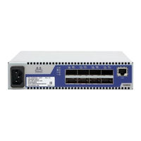
Mellanox Technologies InfiniScale IV User Manual (51 pages)
8-Port QSFP 40Gb/s InfiniBand Switch
Brand:
Mellanox Technologies
| Category:
Switch
| Size: 1.75 MB
Table of Contents
Contents
3
Table of Contents
3
List of Figures
5
List of Tables
6
Revision History
7
Table 1: Revision History Table
7
About this Manual
8
Intended Audience
8
Related Documentation
8
Conventions
8
Table 2: Reference Documents
8
Mellanox Part Numbering Legend
9
Chapter 1 Overview
10
Serial Number and Product Version Information
10
Figure 1: Generic Product Label
10
Chapter 2 Installation Safety Warnings
11
Chapter 3 Externally Managed Switches
14
Chapter 4 Hardware Basic Operation and Installation
15
Switch Platform Hardware Overview
15
LED Assignments
15
Figure 2: Switch System Front Panel
15
Figure 3: Status Leds
16
Table 3: Switch Status LED Configurations
16
Table 4: Fan LED Configurations
17
Table 5: Bad Port LED Configurations
17
Air Flow
18
QSFP Cable Power Budget Classification
18
Table 6: Connector Physical and Logical Link Indications
18
Interfaces
19
Port Connector Interfaces
19
Management and FW Updating Interfaces
19
Connector (I2C)
19
Figure 4: Port Numbering
19
Figure 5: Top and Bottom Ports
19
Figure 6: RJ45 I2C Connector
20
Chapter 5 Installation
21
Package Contents
21
Table 7: Installation Kit Options
21
Installing the Switch in the Rack
22
Table Top Installation
22
Figure 7: Placing the Bumpers
22
Installation Procedure for a Single Switch Center-Of-Rack Installation
23
Figure 8: Installation Kit for a Single Centered Installation
23
Installation Procedure for a Side by Side Installation
24
Figure 9: Connect the Mounting Brackets
24
Figure 10: Installation Kit Parts for a Side by Side Installation
25
Figure 11: Screw on the Switch Mounted Rails
25
Figure 12: Caged Nut Placement
26
Figure 13: Front Panel Orientation
26
Grounding the Switch
27
Power Connections and Initial Power on
27
Infiniband Cable Installation
27
Disassembly of the Switch from the Rack
28
Disassembly Procedure - Single Switch Centered Installation
28
Figure 14: Top and Bottom Ports
28
Disassembly Procedure - Side by Side Installation
29
Disposal
29
Updating Firmware
29
Current Firmware Revision
29
Figure 15: MTUSB-1 with Cables
31
How to Get Mellanox Firmware Tools (MFT)
32
Open SM
32
Chapter 6 Troubleshooting
33
Appendix A Specification
35
Table 8: IS5022 Specification Data
35
EMC Certification Statements
36
Table 9: Switch Certification Status
36
MIC Certification (Korea)
39
VCCI Statements (Japan)
39
Appendix B QSFP Interface
40
Table 10: Infiniband QSFP Connector Pinout
40
Figure 17: QSFP Male and Female Connections
41
Appendix C RJ45 I2C Interface
42
Table 11: Replacement Parts Ordering Numbers
43
QDR Infiniband Switch Platform User Manual Rev
45
Appendix F Installation - Sicherheitshinweise (German)
46
Advertisement
Advertisement
Related Products
Mellanox Technologies InfiniScale III
Mellanox Technologies IS5025Q-1SFC
Mellanox Technologies IS5025Q-1SRC
Mellanox Technologies IS5030Q-1SFC
Mellanox Technologies IS5035Q-1BFC
Mellanox Technologies IS5035Q-1BRC
Mellanox Technologies IS5035Q-2BRC
Mellanox Technologies IS5035Q-1SFC
Mellanox Technologies IS5025
Mellanox Technologies IS5030
Mellanox Technologies Categories
Switch
Computer Hardware
Adapter
Network Card
Network Router
More Mellanox Technologies Manuals
Login
Sign In
OR
Sign in with Facebook
Sign in with Google
Upload manual
Upload from disk
Upload from URL