Sign In
Upload
Manuals
Brands
Keithley Manuals
Measuring Instruments
6514
Keithley 6514 Manuals
Manuals and User Guides for Keithley 6514. We have
2
Keithley 6514 manuals available for free PDF download: Instruction Manual, Quick Manual
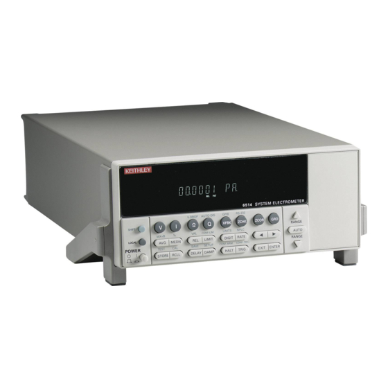
Keithley 6514 Instruction Manual (334 pages)
System electrometer
Brand:
Keithley
| Category:
Measuring Instruments
| Size: 4.03 MB
Table of Contents
Table of Contents
7
Getting Started
23
General Information
24
Warranty Information
24
Contact Information
24
Safety Symbols and Terms
24
Inspection
24
Getting Started
24
Options and Accessories
25
System Electrometer Features
26
Front and Rear Panel Familiarization
27
Front Panel Summary
27
Figure 1-1 Model 6514 Front Panel
27
Rear Panel Summary
30
Figure 1-2 Model 6514 Rear Panel
30
Power-Up
32
Line Power Connection
32
Line Frequency Selection
32
Table 1-1 SCPI Commands - Line Frequency
32
Power-Up Sequence
33
Display
34
Status and Error Messages
34
Default Settings
34
Table 1-2 Default Settings
35
SCPI Programming
37
Measurement Concepts
38
Measurement Overview
39
Performance Considerations
39
Warm-Up Period
39
Autozero
39
Table 2-1 Basic Measurement Capabilities
39
Connection Fundamentals
40
Input Connector
40
Table 2-2 SCPI Commands — Autozero
40
Low Noise Input Cables
42
Figure 2-2 Maximum Input Levels
42
Basic Connections to DUT
43
Figure 2-3 Basic Connections for Unguarded Measurements
43
Figure 2-4 Shielding for Unguarded Measurements
44
Test Fixture
46
Input Protection
48
Floating Measurements
48
Figure 2-7 Capacitor Test Circuit Without Protection
48
Figure 2-8 Capacitor Test Circuit with Protection
48
Figure 2-9 Floating Measurements
49
Zero Check and Zero Correct
50
Zero Check
50
Table 2-3 Display Messages for Zero Check and Zero Correct
50
Zero Correct
51
Figure 2-10 Equivalent Input Impedance with Zero Check Enabled
51
SCPI Programming - Zero Check and Zero Correct
52
Table 2-4 SCPI Commands — Zero Check and Zero Correct
52
Input Bias Current and Offset Voltage Calibration
54
Front Panel
54
SCPI Programming
55
Table 2-5 SCPI Commands — Input Bias Current and Offset Voltage Calibration
55
Measurement Considerations
56
Table 2-6 Summary of Measurement Considerations
56
Volts and Ohms Measurements
58
Measurement Overview
59
Guarding
59
Test Circuit Leakage
59
Input Cable Leakage and Capacitance
60
Figure 3-1 High-Impedance Voltage Measurements
60
Volts and Ohms Measurement Procedure
61
Figure 3-2 Connections for Unguarded Volts and Ohms
62
V-Drop and I-Source for Ohms
63
SCPI Programming
64
Table 3-1 SCPI Commands — Volts and Ohms Function
64
Programming Example
65
Volts and Ohms Measurement Considerations
66
Loading Effects
66
Cable Leakage Resistance
66
Figure 3-4 Meter Loading
66
Input Capacitance (Settling Time)
67
Figure 3-5 Effects of Input Capacitance
68
Guarding Input Cable
69
Figure 3-6 Settling Time
69
Figure 3-7 Unguarded Input Cable
69
Figure 3-8 Guarded Input Cable
70
Application
71
Capacitor Dielectric Absorption
71
Figure 3-9 Measuring Dielectric Absorption
72
Amps Measurements
73
Measurement Overview
74
Amps Measurement Procedure
74
Damping
76
Figure 4-1 Connections for Amps
76
High Impedance Measurement Techniques
77
Figure 4-2 High Impedance Current Measurements
77
Figure 4-3 Floating Current Measurements
79
SCPI Programming
80
Table 4-1 SCPI Commands — Amps Function
80
Programming Example
81
Amps Measurement Considerations
81
Input Bias Current
81
Voltage Burden
81
Noise
82
Figure 4-4 Voltage Burden Considerations
82
Figure 4-5 Source Resistance and Capacitance
83
Table 4-2 Minimum Recommended Source Resistance Values
83
Applications
85
Diode Leakage Current
85
Figure 4-6 Connections; Diode Leakage Current Test
85
Capacitor Leakage Current
86
Cable Insulation Resistance
86
Figure 4-7 Connections; Capacitor Leakage Current Test
86
Figure 4-8 Connections; Cable Insulation Resistance Test
86
Figure 4-9 Connections; Surface Insulation Resistance Test
87
Surface Insulation Resistance (SIR)
87
Coulombs Measurements
88
Measurement Overview
89
Auto Discharge
89
Coulombs Measurement Procedure
90
Figure 5-1 Typical Connections for Coulombs
91
Table 5-1 SCPI Commands — Coulombs Function
92
SCPI Programming
92
Programming Example
93
Coulombs Measurement Considerations
93
Input Bias Current
93
External Voltage Source
93
Zero Check Hop and Auto Discharge Hop
94
5 Coulombs Measurements
94
Application
94
Capacitance Measurements
94
Figure 5-2 Measuring Capacitors
94
Range, Units, Digits, Rate, and Filters
95
6 Range, Units, Digits, Rate, and Filters
96
Range, Units, and Digits
96
Range
96
Table 6-1 Measurement Ranges
96
Units
98
Digits
98
SCPI Programming - Range and Digits
98
Table 6-2 SCPI Commands — Range and Digits
98
Rate
100
Figure 6-1 Speed Vs. Noise Characteristics
100
SCPI Programming - Rate
101
Table 6-3 SCPI Commands - Rate
101
Filters
102
Median Filter
102
Digital Filter
103
SCPI Programming - Filters
104
Relative, MX+B and Percent (%)
106
Relative
107
Setting and Controlling Relative
107
SCPI Programming - Relative
108
Table 7-1 Range Symbols for Rel Values
108
Table 7-2 SCPI Commands - Relative (Null)
108
7 Relative, MX+B and Percent (%)
108
MX+B and Percent (%)
109
MX+B
109
Percent (%)
110
SCPI Programming - MX+B and Percent
111
Table 7-3 SCPI Commands — MX+B and Percent
111
Buffer
112
Store
112
Recall
112
Buffer Operations
113
Store
113
Recall
113
Buffer Statistics
113
Buffer Statistics
114
Figure 8-1 Buffer Locations
114
8 Buffer
114
SCPI Programming
115
Programming Example
117
Triggering
118
Trigger Models
119
Figure 9-2 Trigger Model — Remote Operation
120
Idle and Initiate
121
Trigger Model Operation
121
Figure 9-3 Measure Action Block of Trigger Model
123
Table 9-1 Auto Delay Settings
123
Trigger Model Configuration - Front Panel
124
SCPI Programming
126
Table 9-2 SCPI Commands — Triggering
126
Programming Example
127
External Triggering
128
Input Trigger Requirements
128
Figure 9-4 Trigger Link Connection Operation
128
Figure 9-5 Trigger Link Input Pulse Specifications
128
Output Trigger Specifications
129
External Trigger Example
129
Figure 9-7 DUT Test System
129
Figure 9-9 Operation Model for Triggering Example
131
Limit Tests
132
10 Limit Tests
133
Limit Testing
133
Figure 10-1 Limit Tests
133
Figure 10-2 Limit Tests Example
133
Figure 10-3 Operation Model for Limit Test
134
Table 10-1 Test Limit Display Messages
134
Binning
135
Figure 10-4 Binning System
135
Figure 10-5 Operation Model for Limit Testing with Binning
136
Component Handler Interface
137
Figure 10-6 Handler Interface Connections
137
Component Handler Types
138
Digital Output Clear Pattern
139
Front Panel Operation
141
Limit Test Configuration
141
Perform Limit Tests
142
SCPI Programming
143
Table 10-2 SCPI Commands — Limit Tests
143
Programming Example
146
Digital I/O, Analog Outputs, and External Feedback
147
Analog Outputs
147
11 Digital I/O, Analog Outputs, and External Feedback
148
Digital I/O Port
148
Figure 11-1 Digital I/O Port
148
Sink Mode - Controlling External Devices
149
Figure 11-3 Controlling Externally Powered Relays
150
Figure 11-4 NAND Gate Control
151
Setting Digital Output Lines
151
Source Mode - Logic Control
151
SCPI Programming - Digital Output Pattern
152
Table 11-1 SCPI Commands — Digital Outputs
152
Analog Outputs
153
2V Analog Output
153
Table 11-2 Example 2V Analog Output Values
153
Figure 11-5 Typical 2V Analog Output Connections
154
Figure 11-6 Typical Preamp out Connections
155
Table 11-3 Full-Range Preamp out Values
156
External Feedback
157
Electrometer Input Circuitry
157
Shielded Fixture Construction
158
Figure 11-7 Electrometer Input Circuitry (External Feedback Mode)
158
Non-Standard Coulombs Ranges
159
External Feedback Procedure
159
Figure 11-8 Shielded Fixture Construction
160
Logarithmic Currents
161
Non-Decade Current Gains
162
Figure 11-10 Non-Decade Current Gains
162
SCPI Programming - External Feedback
163
Table 11-4 SCPI Commands — External Feedback
163
Remote Operation
164
Selecting and Configuring an Interface
165
Interfaces
165
Languages
165
Interface Selection and Configuration Procedures
165
12 Remote Operation
168
GPIB Operation and Reference
168
GPIB Bus Standards
168
GPIB Bus Connections
168
Figure 12-1 IEEE-488 Connector
168
Figure 12-2 IEEE-488 Connections
169
Primary Address Selection
170
Figure 12-3 IEEE-488 Connector Location
170
General Bus Commands
171
Front Panel GPIB Operation
173
Programming Syntax
174
RS-232 Interface Reference
180
Sending and Receiving Data
180
RS-232 Settings
180
RS-232 Connections
181
Figure 12-4 RS-232 Interface Connector
181
Error Messages
182
Status Structure
183
Overview
184
13 Status Structure
185
Figure 13-1 6514 Status Mode Structure
185
Clearing Registers and Queues
186
Table 13-1 Common and SCPI Commands — Reset Registers and Clear Queues
186
Programming and Reading Registers
187
Programming Enable Registers
187
Reading Registers
188
Table 13-2 SCPI Command — Data Formats for Reading Status Registers
188
Status Byte and Service Request (SRQ)
189
Status Byte Register
189
Figure 13-3 Status Byte and Service Request
189
Service Request Enable Register
190
Serial Polling and SRQ
191
Status Byte and Service Request Commands
191
Table 13-3 Common Commands — Status Byte and Service Request Enable Registers
191
Status Register Sets
193
Register Bit Descriptions
193
Figure 13-4 Standard Event Status
194
Figure 13-5 Operation Event Status
195
Measurement Event Status
196
Condition Registers
197
Figure 13-7 Questionable Event Status
197
Event Registers
198
Table 13-4 Common and SCPI Commands — Condition Registers
198
Table 13-5 Common and SCPI Commands — Event Registers
198
Event Enable Registers
199
Table 13-6 Common and SCPI Commands — Event Enable Registers
199
Queues
200
Output Queue
200
Error Queue
201
Table 13-7 SCPI Commands — Error Queue
202
Common Commands
203
Table 14-1 IEEE-488.2 Common Commands and Queries
204
SCPI Signal Oriented Measurement Commands
207
Table 15-1 Signal Oriented Measurement Command Summary
208
Display, Format, and System
211
Display Subsystem
212
Table 16-1 SCPI Commands — Display
212
Format Subsystem
214
Table 16-2 SCPI Commands — Data Format
214
16 Display, Format, and System
215
Figure 16-1 ASCII Data Format
215
System Subsystem
218
Table 16-3 SCPI Commands — System
218
Figure 16-3 Key-Press Codes
220
17 SCPI Reference Tables
221
SCPI Reference Tables
221
Table 17-1 Calculate Command Summary
221
Table 17-4 Sense Command Summary
221
Table 17-7 System Command Summary
221
Table 17-8 Trace Command Summary
221
Table 17-9 Trigger Command Summary
221
General Notes
222
Table 17-2 Format Command Summary
225
Table 17-3 Display Command Summary
225
Performance Verification
235
Introduction
236
Verification Test Requirements
237
Environmental Conditions
237
Warm-Up Period
237
Line Power
237
Recommended Test Equipment
238
18 Performance Verification
239
Table 18-1 Recommended Verification Equipment
239
Verification Limits
240
Example Reading Limits Calculation
240
Recalculating Resistance Reading Limits
240
Calibrator Voltage Calculations
241
Current Calculations
241
Charge Calculations
241
Performing the Verification Test Procedures
242
Test Summary
242
Test Considerations
242
Restoring Factory Defaults
243
Input Bias Current and Offset Voltage Calibration
243
Offset Voltage Calibration
243
Input Bias Current Calibration
243
Volts Measurement Accuracy
244
Table 18-2 Voltage Measurement Accuracy Reading Limits
245
Amps Measurement Accuracy
246
20Μa-20Ma Range Accuracy
246
20Pa-2Μa Range Accuracy
247
Table 18-4 20Pa-2Μa Range Current Measurement Accuracy Reading Limits
248
Ohms Measurement Accuracy
249
2Kω-20MΩ Range Accuracy
249
Table 18-5 2Kω-20MΩ Range Resistance Measurement Accuracy Limits
250
200MΩ-200GΩ Range Accuracy
251
Table 18-6 200MΩ-200GΩ Resistance Measurement Accuracy Limits
251
Coulombs Measurement Accuracy
252
Table 18-7 Coulombs Measurement Accuracy Reading Limits
253
Calibration
254
Introduction
255
Environmental Conditions
255
Temperature and Relative Humidity
255
Warm-Up Period
255
Line Power
255
Calibration Considerations
256
Calibration Cycle
256
Recommended Calibration Equipment
256
19 Calibration
257
Table 19-1 Recommended Calibration Equipment
257
Calibration Errors
258
Calibration Menu
258
Aborting Calibration
258
Table 19-2 Calibration Menu
258
Current and Charge Calculations
259
Manual Calculations
259
Automatic Calculations
259
Calibration Procedure
260
Preparing for Calibration
260
Input Bias Current and Offset Voltage Calibration
260
Volts Calibration
261
Figure 19-1 Connections for Volts Calibration
261
Table 19-3 Volts Calibration Summary
262
Amps Calibration
263
Figure 19-2 Connections for 20Μa-20Ma Range Calibration
263
Table 19-5 20Pa-2Μa Range Amps Calibration Summary
266
Coulombs Calibration
267
Table 19-6 Coulombs Calibration Summary
268
Ohms Calibration
269
Figure 19-6 Connections for Ohms Calibration (2GΩ Range)
270
Table 19-7 Ohms Calibration Summary
270
Entering Calibration Dates and Saving Calibration
271
Locking out Calibration
271
Changing the Calibration Code
271
Resetting the Calibration Code
272
Displaying Calibration Dates
272
Displaying the Calibration Count
273
Routine Maintenance
274
Introduction
275
Setting Line Voltage and Replacing Line Fuse
275
20 Routine Maintenance
276
20 Routine Maintenance
276
Figure 20-1 Power Module
276
Table 20-1 Power Line Fuse
276
DISP Test
277
Front Panel Tests
277
KEY Test
277
Table 20-2 Front Panel Tests
277
Status and Error Messages
282
B Status and Error Messages
283
Table B-1 Status and Error Messages
283
General Measurement Considerations
288
100 C General Measurement Considerations
289
Measurement Considerations
289
Ground Loops
289
Figure C
289
Triboelectric Effects
290
Piezoelectric and Stored Charge Effects
290
Figure C
290
Electrochemical Effects
291
Humidity
291
Light
291
Electrostatic Interference
291
Magnetic Fields
292
Electromagnetic Interference (EMI
292
DDC Emulation Commands
294
500 D DDC Emulation Commands
295
DDC Language
295
Table D-1 Device Dependent Command Summary
295
Example Programs
299
Programming Examples
300
Changing Function and Range
300
One-Shot Triggering
301
Generating SRQ on Buffer Full
302
Storing Readings in Buffer
303
Taking Readings Using the :READ? Command
304
Controlling the Model 6514 Via the RS-232 COM2 Port
305
IEEE-488 Bus Overview
306
Introduction
307
Figure F
308
Bus Description
308
Figure F
309
Bus Lines
310
Data Lines
310
Bus Management Lines
310
Handshake Lines
311
Figure F
311
F IEEE-488 Bus Overview
311
F IEEE-488 Bus Overview
312
Bus Commands
312
Table F-1 IEEE-488 Bus Command Summary
312
Uniline Commands
313
Universal Multiline Commands
313
Addressed Multiline Commands
314
Address Commands
314
Unaddress Commands
314
Common Commands
315
SCPI Commands
315
Command Codes
315
Table F-2 Hexadecimal and Decimal Command Codes
315
Typical Command Sequences
316
Table F-3 Typical Bus Sequence
316
Table F-4 Typical Addressed Command Sequence
316
IEEE Command Groups
317
Table F-5 IEEE Command Groups
317
Interface Function Codes
318
IEEE-488 and SCPI Conformance Information
320
Table G-1 IEEE-488 Documentation Requirements
321
Introduction
321
G IEEE-488 and SCPI Conformance Information
323
Table G-2 Coupled Commands
323
Calibration Options
324
H Calibration Options
325
Figure H
325
Introduction
325
Reading Calibration Standard Values
325
Data Transfer Connections
325
Reading Values
325
Example Program
326
H Calibration Options
327
Remote Calibration
327
Calibration Commands
327
Remote Calibration Overview
327
Calibration
327
Calibration Options
327
Command Codes
329
Data Transfer Connections
329
Advertisement
Keithley 6514 Quick Manual (30 pages)
Electrometer
Brand:
Keithley
| Category:
Measuring Instruments
| Size: 0.37 MB
Table of Contents
Table of Contents
7
Introduction
10
Measurement Capabilities
10
Front and Rear Panels
11
Basic Connections
12
Input Connector
12
Low Noise Input Cables
12
Basic Connections to DUT
13
Basic Operation
15
Selecting Operating Modes
15
Making Volts and Ohms Measurements
15
Quick Results Guide
15
Making Amps Measurements
16
Making Charge Measurements
16
Measurement Considerations
17
Remote Command Programming
17
Settings to Optimize Performance
19
Range
19
Rate
20
Digits
20
Filter
20
REL Key
21
Remote Command Programming
22
Features to Enhance DUT Testing
23
Buffer
23
SCPI Commands: Buffer
24
Limit Testing
25
Table 10
25
Command Sequence for Buffer Example
25
Limit Test Display Messages
25
Table 12
26
SCPI Commands: Basic Limit Testing
26
Math Operations
27
Table 13
27
Command Sequence for Limit Test Example
27
Table 14
28
SCPI Commands; MX+B and Percent
28
Command Sequence for MX+B Measurement Example
28
Advertisement
Related Products
Keithley 6517A
Keithley 6517B
Keithley 6517
Keithley 6512
Keithley 6487
Keithley 610
Keithley 6221
Keithley 600B
Keithley 630
Keithley 615
Keithley Categories
Measuring Instruments
Multimeter
Power Supply
Test Equipment
Switch
More Keithley Manuals
Login
Sign In
OR
Sign in with Facebook
Sign in with Google
Upload manual
Upload from disk
Upload from URL