Sign In
Upload
Manuals
Brands
Keithley Manuals
Measuring Instruments
6517
Keithley 6517 Manuals
Manuals and User Guides for Keithley 6517. We have
2
Keithley 6517 manuals available for free PDF download: Service Manual, Getting Started Manual
Keithley 6517 Service Manual (119 pages)
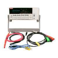
Electrometer
Brand:
Keithley
| Category:
Measuring Instruments
| Size: 2 MB
Table of Contents
Table of Contents
7
1 Performance Verification
14
Introduction
14
Environmental Conditions
14
Warm-Up Period
15
Line Power
15
Recommended Test Equipment
15
Meter Performance Verification Equipment
15
Performance Verification
15
Voltage Source Verification Equipment
16
Temperature Verification Equipment
16
Table
16
Recommended Test Equipment for Meter Performance Verification
16
Recommended Test Equipment for Voltage Source Verification
16
Humidity Verification Equipment
17
Verification Limits
17
Restoring Default Conditions
17
Table
17
Offset Voltage and Bias Current Calibration
18
Front Panel Offset Calibration
18
IEEE-488 Bus Offset Calibration
18
Meter Verification Procedures
18
DC Volts Verification
19
DC Amps Verification
19
Table
19
Limits for DC Volts Verification
19
Table
21
Reading Limits for Verification of 20Pa-2Μa Ranges
21
Coulombs Verification
22
Table
22
Limits for 20Μa-20Ma Range Verification
22
Table
23
Limits for Coulombs Verification
23
Ohms Verification
24
Table
25
Limits for Ohms Verification
25
Voltage Source Verification
27
Temperature Verification
28
Table
28
Limits for Voltage Source Verification
28
Reading Limits for Temperature Verification
28
Humidity Verification
29
Table
29
Limits for Humidity Verification
29
2 Calibration
31
Introduction
31
Environmental Conditions
32
Warm-Up Period
32
Line Power
32
Recommended Calibration Equipment
32
Table
33
Table 2-1 Recommended Calibration Equipment
33
Calibration Lock
34
Unlocking Calibration
34
IEEE-488 Bus Calibration Lock Status
34
Calibration Errors
34
Front Panel Error Reporting
34
IEEE-488 Bus Error Reporting
34
Front Panel Calibration
34
Front Panel Calibration Summary
34
Table
35
Table 2-2 Front Panel Calibration Summary
35
Front Panel Calibration Procedure
36
Figure 2-1 Calibration Unit Connections
37
Figure 2-2 Connections for DC Volts Calibration
38
Table
38
Volts Calibration Summary
38
Figure 2-3 Connections for 20Pa–2Μa Range Calibration
39
Amps Calibration Summary (20Pa-2Μa Ranges)
40
Amps Calibration Summary (20Μa-20Ma Ranges)
40
Figure 2-4 Connections for 20Μa–20Ma Range Calibration
40
Table
40
Figure 2-5 Connections for Coulombs Calibration
41
Coulombs Calibration Summary
42
Figure 2-6 Connections for Temperature Calibration
42
Table
42
Figure 2-7 Connections for Voltage Source Calibration
43
Table
43
Voltage Source Calibration Summary
43
Humidity Calibration Summary
44
Table
44
Figure 2-8 Connections for Humidity Calibration
44
IEEE-488 Bus Calibration
45
Calibration Commands
45
IEEE-488 Bus Comprehensive Calibration Procedure
45
Offset Calibration Steps
45
Table
45
IEEE-488 Bus Volts Function Calibration Summary
46
Table
46
IEEE-488 Bus Amps Calibration Summary (20Pa-2Μa Ranges)
48
IEEE-488 Bus Amps Calibration Summary (20Μa-20Ma Ranges)
48
IEEE-488 Bus Coulombs Calibration Summary
49
Table
49
IEEE-488 Bus Voltage Source Calibration Summary
50
Table
50
Single-Point Calibration
51
Front Panel Single-Point Calibration
51
IEEE-488 Bus Humidity Calibration Summary
51
IEEE-488 Bus Single-Point Calibration
52
Programming Calibration Dates
53
3 Calibration Command Reference
54
Introduction
54
Command Summary
54
Calibration Command Reference
55
IEEE-488 Bus Calibration Command Summary
55
Table
55
Table 3-1 IEEE-488 Bus Calibration Command Summary
55
Table
56
Miscellaneous Commands
58
INIT (:Calibration:protected:initiate)
58
LOCK (:Calibration:protected:lock)
58
SAVE (:Calibration:protected:save)
59
Switch? (:Calibration:protected:switch?)
59
DATE (:Calibration:protected:date)
60
NDUE (:Calibration:protected:ndue)
60
CALTEMP (:Calibration:protected:caltemp)
61
DATA? (:Calibration:protected:data?)
61
Meter Commands
62
Offset Commands
62
Volts Function Calibration Commands
63
Volts Function Calibration Commands and Parameters
63
Amps Calibration Commands
64
Amps Function Calibration Commands and Parameters (All Ranges, Without Calibration Standard)
64
Table 3-4 Amps Function Calibration Commands and Parameters (20Pa-2Μa Ranges, Using Calibration Standard)
65
Coulombs Calibration Commands
66
Coulombs Function Calibration Commands and Parameters (Without Calibration Standard)
66
Coulombs Function Calibration Commands and Parameters (Using Calibration Standard)
67
Voltage Source Calibration Commands
68
Table
68
Temperature Calibration Commands
69
Humidity Calibration Commands
69
Calibration Errors
70
Error Query Commands
70
Detecting Calibration Errors
71
Detecting Calibration Step Completion
71
Using the *OPC? Query
71
Using the *OPC Command
71
Generating an SRQ on Calibration Complete
71
4 Routine Maintenance
72
Introduction
72
Line Voltage Selection
72
Line Fuse Replacement
72
INPUT Connector Cleaning
73
Firmware Updates
73
Table 4-1 Power Line Fuse
73
5 Troubleshooting
74
Introduction
74
Repair Considerations
74
Power-On Test
75
Front Panel Tests
75
KEYS Test
75
DISPLAY PATTERNS Test
75
Character Set Test
75
Principles of Operation
75
Figure 5-1 Model 6517A Overall Block Diagram
76
Display Board
77
Power Supply
77
Figure 5-3 Power Supply Block Diagram
78
Digital Board
79
Analog Board
80
Power Supply Circuits
80
Figure 5-5 Analog Board Block Diagram
81
Circuit Board Checks
83
Display Board Checks
83
Table
83
Power Supply Checks
84
Table
84
Table 5-3 Power Supply Checks
84
Digital Board Checks
85
Analog Board Checks
86
Table 5-5 Analog Board Checks
86
6 Disassembly
88
Introduction
88
Handling and Cleaning Precautions
88
PC Board Handling
88
Solder Repairs
89
Special Handling of Static-Sensitive Devices
89
Case Cover Removal
89
PC Board Removal
89
Digital Board Removal
90
A/D Converter Board Removal
90
Analog Board Removal
90
Front Panel Disassembly
91
Main CPU Firmware Replacement
91
Instrument Re-Assembly
92
Assembly Drawings
92
7 Replaceable Parts
93
Introduction
93
Parts Lists
93
Ordering Information
93
Factory Service
93
Component Layouts
93
Model 6517A ADC Board, Parts List
95
Table
95
Table 7-1 Model 6517A ADC Board, Parts List
95
Table
96
Model 6517A Display Board, Parts List
97
Table
97
Model 6517A Analog Board, Parts List
98
Table
99
Model 6517A Digital Board, Parts List
102
Table
102
Model 6517A Mechanical Board, Parts List
104
Table
104
Model 6517A Miscellaneous Parts List
105
Calibration Messages
106
Table
107
Calibration Error Responses
107
Table B-1 Calibration Error Responses
107
Table
108
Calibration Error Query Commands
109
Calibration Constants Returned by :CAL:PROT:DATA? Query
110
Table
110
Table B-3 Calibration Constants Returned by :CAL:PROT:DATA? Query
110
Figure B-1 EERR? Query Response (Calibration Execution Errors)
111
Figure B-4 CERR? Query Response (Coulombs Function Cal Errors)
112
100 C Calibration Command Summary
113
Calibration Command Summary
113
Table
113
Table C-1 Calibration Commands
113
Calibration Commands
114
Advertisement
Keithley 6517 Getting Started Manual (104 pages)
Electrometer/High Resistance Meter
Brand:
Keithley
| Category:
Measuring Instruments
| Size: 1 MB
Table of Contents
Table of Contents
7
1 Front Panel Operation
12
Product Overview
13
Figure 1-1 Model 6517A Front Panel Overview
15
Figure 1-2 Model 6517A Rear Panel Overview
17
Display
19
Power-Up
19
Warm-Up
19
Bench Defaults
20
Changing Functions
20
Voltage Measurements
21
Figure 1-3 Voltage Measurements
22
Guarding
23
Current Measurements
23
Figure 1-4 Current Measurements
24
Resistance Measurements
25
Figure 1-5 Resistance Measurements
26
Amps Rel
27
Auto V-Source
27
Resistivity Measurements
28
Figure 1-6 Resistivity Measurements
30
Charge Measurements
31
Auto Discharge
32
External Temperature and Relative Humidity Measurements
33
Connections
33
Measurement Control
34
Temperature Units
34
Display Reading Options
35
2 Measurement Options
36
Multiple Displays
37
Menus
40
Navigating Menus
41
Table 2-5 Menu Summary
42
Voltage Source
43
Connections
43
Basic Operation
44
Configuring V-Source
45
Relative
45
Configuring Rel
45
Zero Check
46
Zero Correct
46
Triggering
47
Idle
48
Control Sources
49
Device Action
49
Output Trigger
49
Counters (Advanced Triggering)
49
Bench Default Trigger Model Setup
50
Speed
50
Configuring Speed
50
Resolution
51
Configure Resolution
51
Filter
51
Filter Types
51
Filter Modes
52
Median Filter
52
Configuring Filters
53
Buffer (Data Store)
54
Storing Readings
54
Math
55
Selecting and Configuring Math
56
Enabling Math
57
Additional Math Operations
57
Test Sequences
58
Selecting and Configuring a Test Sequence
58
Connections
59
Running a Test
60
Internal Scanning
61
Configure Internal Scanner
61
Perform the Scan
62
Close/Open Channels
63
External Scanning
63
Trigger Connections
63
Configure External Channels
64
Perform the Scan
65
3 Remote Operation
67
Overview
68
Software Support
68
Testpoint Application Software
68
Demonstration/Startup Programs
68
Labview Driver
68
IEEE-488 Bus Standards
69
RS-232 Standard
69
IEEE-488 Bus Connections
69
RS-232 Connections
70
IEEE-488 Interface, Address and Language Selection
70
RS-232 Interface Selection and Configuration
71
Common Commands
72
SCPI Commands
73
SCPI Command Syntax
74
Tree Structure
74
Long and Short Form Commands
75
Query Commands
75
Default Nodes
75
Command Syntax
76
SCPI Signal Oriented Commands
76
Fetch
76
Measure[:<Function>]
76
SCPI Subsystem Commands
77
Defaults
77
Fresh Readings
77
Function Configuration
78
V-Source
80
Data Store (Buffer)
80
Open/Close Channels and Scan
80
Trigger Model
81
Test Sequences
82
Status Register
83
Program Examples
84
Changing Function and Range
84
One-Shot Triggering
85
Continuous Triggering #1
87
Continuous Triggering #2
88
Generating SRQ on Buffer Full
89
Storing Readings in Buffer
90
Taking Readings with the Scanner Card
92
Test Sequence - Staircase Sweep
94
4 Specs and Accessories
96
Advertisement
Related Products
Keithley 6514
Keithley 6517A
Keithley 6517B
Keithley 6512
Keithley 6485
Keithley 610
Keithley 617
Keithley 616
Keithley 600A
Keithley 661
Keithley Categories
Measuring Instruments
Multimeter
Test Equipment
Power Supply
Switch
More Keithley Manuals
Login
Sign In
OR
Sign in with Facebook
Sign in with Google
Upload manual
Upload from disk
Upload from URL