Sign In
Upload
Manuals
Brands
Keithley Manuals
Measuring Instruments
6512
Keithley 6512 Manuals
Manuals and User Guides for Keithley 6512. We have
1
Keithley 6512 manual available for free PDF download: Instruction Manual
Keithley 6512 Instruction Manual (156 pages)
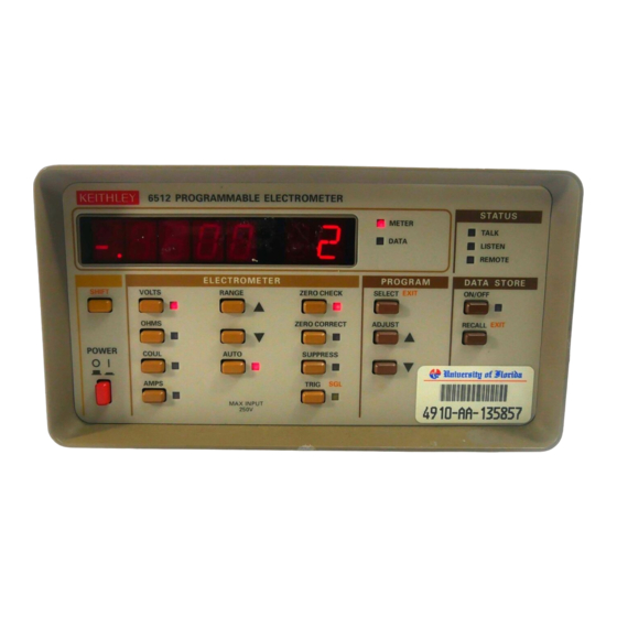
Programmable Electrometer
Brand:
Keithley
| Category:
Measuring Instruments
| Size: 1 MB
Table of Contents
Table of Contents
8
General Information
17
Introduction
17
Features
17
Warranty Information
17
Manual Addenda
18
Safety Symbols and Terms
18
Specifications
18
Unpacking and Inspection
18
Shipment Contents
18
Instruction Manual
18
Repacking for Shipment
18
Getting Started
18
Preparation for Use
18
Quick Start Procedure
19
Accessories
19
Operation
21
Introduction
21
Power-Up Procedure
21
Power-Up Self-Test and Display Messages
22
RAM Memory Test
22
Self-Test and Firmware Revision Level
22
Front Panel Familiarization
22
Controls
22
Figure 2-1 Model 6512 Front Panel
23
Display and Indicators
25
Tilt Bail
25
Front Panel Programs
25
IEEE-488 Address
26
Exponent Mode (Alpha or Numeric)
26
Calibration
26
Rear Panel Familiarization
26
Figure 2-2 Model 6512 Rear Panel
27
Basic Measurement Techniques
28
Warm-Up Period
28
Input Connections
28
Making Voltage Measurements
29
Guarded Operation
31
Figure 2-6 Unguarded Circuit
31
Figure 2-7 Guarded Circuit
31
Making Current Measurements
32
Figure 2-9 Current Measurements
33
Making Charge Measurements
34
Figure 2-11 Coulombs Connections
35
Resistance Measurements
36
Using the Ohms Function as a Current Source
37
Analog Outputs
38
Analog Output
38
Preamp out
39
Using External Feedback
41
Electrometer Input Circuitry
41
Shielded Fixture Construction
42
External Feedback Procedure
42
Non-Standard Coulombs Ranges
43
Logarithmic Currents
43
Non-Decade Current Gains
44
Figure 2-18 Non-Decade Current Gains
44
Using Zero Correct and Baseline Suppression
45
Zero Correct and Zero Check
45
Using Suppression
45
Data Storage
46
External Triggering
48
External Trigger Input
48
Meter Complete Output
49
Triggering Example
49
Measurement Considerations
50
Ground Loops
50
Figure 2-24 Eliminating Ground Loops
50
Eiectrostatic Interference
51
Thermal Emfs
51
Electromagnetic Interference (EMI)
51
Leakage Resistance Effects
51
Input Capacitance Effects
52
Source Resistance
53
Source Capacitance
54
Engineering Units Conversion
54
IEEE-488 Programming
56
Introduction
56
Device-Dependent Command Programming
56
Calibration Value (A)
60
Reading Mode (B)
60
Zero Check (C)
61
Function (F)
61
Data Format (G)
62
Figure 3-1 General Data Format
62
EOI and Bus Hold-Off Modes (K)
63
Non-Volatile Memory Storage (L)
64
SRQ Mask (M) and Status Byte Format
64
Baseline Suppression (N)
67
Data Store Mode (Q)
68
Range (R)
69
Trigger Mode (T)
70
Status (U)
71
Terminator (Y)
75
Execute (X)
75
Zero Correct (Z)
76
Bus Connections
77
Primary Address
77
Figure 3-6 IEEE-488 Connector
77
Figure 3-7 IEEE-488 Connections
77
Talk-Only Mode
78
Front Panel Messages
78
Bus Error
79
Number Error
79
Trigger Overrun Error
79
Bus Data Transmission Times
79
Applications
80
Introduction
80
Low-Level Leakage Current Measurements
80
Diode Characterization
82
Capacitor Leakage Measurements
83
Capacitance Measurement
84
Insulation Resistance Measurements
84
Unguarded Resistance Measurements
84
Guarded Resistance Measurements
85
Resistance Measurements with External Voltage Source
85
High-Impedance Voltmeter
88
Voltage Coefficients of High-Megohm Resistors
88
Static Charge Detection
90
Performance Verification
91
Introduction
91
Environmental Conditions
91
Initial Conditions
91
Recommended Test Equipment
91
Verification Procedures
92
Input Current Verification
92
Amps Verification
92
Coulombs Verification
93
Volts Verification
93
Ohms Verification
95
Input Impedance Verification
98
Theory of Operation
99
Introduction
99
Overall Functional Description
99
Input Preamplifier
100
Input Stage
101
Gain Stage
102
Output Stage
102
Figure
102
Ohms Voltage Source
103
Zero Check
103
Additional Signal Conditioning
104
Ranging Amplifier
104
Multiplexer and Buffer Amplifier
104
2V Reference Source
105
A/D Converter
105
Digital Circuitry
107
Microcomputer
107
Memory Elements
107
Device Selection
107
IEEE-488 Bus
107
Input/Output Circuitry
108
Display Circuitry
108
Power Supplies
109
Maintenance
110
Introduction
110
Line Voltage Selection
110
Line Fuse Replacement
111
Calibration
111
Calibration Cycle
111
GUARD Switch
111
Calibration Jumper
111
Required Calibration Equipment
112
Environmental Conditions
112
Calibration Sequence
112
Input Offset Adjustment
112
Input Current Adjustment
113
Calibration Program
113
Amps Calibration
113
Coulombs Calibration
114
Volts Calibration
115
Ohms Calibration
116
Permanent Storage of Calibration Constants
116
IEEE-488 Bus Digital Calibration
116
Additional Calibration Points
117
Special Handling of Static-Sensitive Devices
117
Disassembly Instructions
118
Troubleshooting
120
Recommended Test Equipment
120
Power-Up Self-Test
120
Self-Diagnostic Program
120
Power Supply Checks
121
Relay Configuration
121
Ranging Amplifier Gain Configuration
123
A/D Converter and Display
123
Input and Ranging Amplifiers
123
Digital Circuitry
123
Display Board
123
Input Stage Balancing Procedure
126
Handling and Cleaning Precautions
126
Replaceable Parts
127
Introduction
127
Parts List
127
Ordering Information
127
Factory Service
127
Component Layout Drawings and Schematic Diagrams
127
Bus Overview
135
General Bus Commands
141
Interface Function Codes
143
Example Programs
145
Model 617/6512 Software Compatibility
153
Advertisement
Advertisement
Related Products
Keithley 6514
Keithley 6517A
Keithley 6517B
Keithley 6517
Keithley 6487
Keithley 610C
Keithley 6221
Keithley 615
Keithley 660A
Keithley 610B
Keithley Categories
Measuring Instruments
Multimeter
Test Equipment
Power Supply
Switch
More Keithley Manuals
Login
Sign In
OR
Sign in with Facebook
Sign in with Google
Upload manual
Upload from disk
Upload from URL