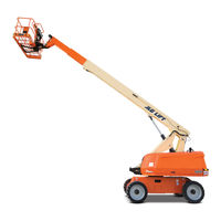
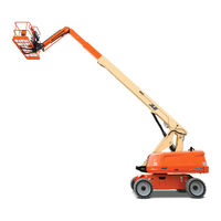
Sign In
Upload
Manuals
Brands
JLG Manuals
Boom Lifts
660SJ
JLG 660SJ Manuals
Manuals and User Guides for JLG 660SJ. We have
6
JLG 660SJ manuals available for free PDF download: Service And Maintenance Manual, Operation And Safety Manual, Manual
JLG 660SJ Service And Maintenance Manual (332 pages)
Brand:
JLG
| Category:
Lifting Systems
| Size: 21 MB
Table of Contents
A General
3
Bhydraulic System Safety
3
Maintenance
3
Table of Contents
5
Specifications
19
Operating Specifications
19
Dimensional Data
19
Capacities
20
Tires
20
Engine Data
20
Function Speeds
21
Machine Orientation When Doing Speed Tests
21
Test Notes
21
Torque Requirements
21
Hydraulic Oil
22
Major Component Weights
23
Operator Maintenance
24
Torque Chart (SAE Fasteners - Sheet 1 of 7)
29
Torque Chart (SAE Fasteners - Sheet 2 of 7)
30
Torque Chart (SAE Fasteners - Sheet 3 of 7)
31
Torque Chart (SAE Fasteners - Sheet 4 of 7)
32
Torque Chart (METRIC Fasteners - Sheet 5 of 7)
33
Torque Chart (METRIC Fasteners - Sheet 6 of 7)
34
Torque Chart (METRIC Fasteners - Sheet 7 of 7)
35
General
37
Machine Preparation, Inspection, and Maintenance
37
Preparation, Inspection, and Maintenance
37
Pre-Start Inspection
37
Pre-Delivery Inspection and Frequent Inspection
37
Annual Machine Inspection
37
Preventive Maintenance
37
Service and Guidelines
38
General
38
Safety and Workmanship
38
Cleanliness
38
Components Removal and Installation
38
Component Disassembly and Reassembly
39
Pressure-Fit Parts
39
Bearings
39
Gaskets
39
Bolt Usage and Torque Application
39
Hydraulic Lines and Electrical Wiring
39
Hydraulic System
39
Lubrication
39
Battery
39
Lubrication and Servicing
39
Lubrication and Information
40
Hydraulic System
40
Hydraulic Oil
40
Changing Hydraulic Oil
40
Lubrication Specifications
40
Cylinder Drift Test
40
Platform Drift
40
Cylinder Drift
40
Pins and Composite Bearing Repair Guidelines
41
Welding on JLG Equipment
41
Do the Following When Welding on JLG Equipment
41
Do NOT Do the Following When Welding on JLG Equipment
41
Deutz Engine and Hydraulic Operating Temperature Specifications
45
GM Engine and Hydraulic Operating Temperature Specifications
46
Chassis & Turntable
47
Tires & Wheels
47
Tire Inflation
47
Tire Damage
47
Tire Replacement
47
Wheel Replacement
47
Wheel Installation
47
Torque Hub
48
Oil Information
48
Roll and Leak Testing
48
Tightening and Torquing Bolts
48
Torque Hub
49
Main Disassembly
50
Output Carrier Disassembly
51
Input Carrier Disassembly
51
Hub-Spindle Disassembly
52
Spindle-Brake Disassembly
53
Cover Disassembly
54
Cover Assembly
54
Input Carrier Assembly
55
Spindle - Brake Assembly
56
Hub-Spindle Assembly
57
Output Planet Gear Assembly
58
Main Assembly
59
Integral Brake Check
59
Hub Assembly
60
Bearing Cup Pressing Tool
61
Bearing Cup Pressing Tool
62
Free Wheeling Option
63
Engage Drive Motors & Brakes (Normal Operation)
63
Drive Motor
63
Description
63
Shaft Seal Replacement
64
Loop Flushing Valve
65
Troubleshooting
66
Disassembly
67
End Cap
68
Cylinder Kit
69
Shaft & Front Bearing
70
Inspection
71
Assembly
73
Swash Plate and Journal Bearing
74
Shaft and Front Bearing
75
Valve Plate and Rear Bearing
76
Shaft Seal
77
Initial Start-Up Procedures
78
Oscillating Axle Bleed Procedure and Lockout Test
78
Lockout Cylinder Bleeding
78
Oscillating Axle Lockout Test
79
Steer Adjustments
79
Swing Drive
80
Swing Motor and Brake Assembly
81
Gear Backlash
82
Swing Drive Lubrication
82
Motor Control Valve Disassembly
83
Motor and Brake Disassembly
83
Main Disassembly
84
Hub-Shaft Disassembly
84
Carrier Disassembly
85
Hub-Shaft Subassembly
86
Carrier Subassembly
87
Main Assembly
88
Motor and Brake Assembly
89
Motor Control Valve Assembly
89
Swing Bearing
90
Turntable Bearing Mounting Bolt Condition Check
90
Wear Tolerance
90
Swing Bearing Replacement
92
Swing Bearing Torque Values
93
Rotary Coupling
94
Rotary Coupling - Sheet 2 of 2
95
Rotary Coupling Port Location - 2WS
96
Rotary Coupling Port Location - 4WS
97
Generator
98
Every 250 Hours
98
Every 500 Hours
98
Overload Protection
99
Inspecting Brushes, Replacing Brushes, and Cleaning Slip Rings
99
Inspecting Generator Brushes, Replacing Brushes, and Cleaning Slip Rings
100
Deutz D2.9 L4 Engine
101
Deutz D2.9 L4 Engine Installation - Sheet 2 of 2
102
Check Oil Level
103
Change Engine Oil
103
Change Oil Filter
104
Change Fuel Filters
104
Deutz D2011 Engine
105
Deutz D2011 Engine Installation - Sheet 2 of 2
106
Checking Oil Level
107
Changing Engine Oil
107
Changing Oil Filter
108
Replace Fuel Filter
108
Clean Fuel Strainer
109
Spark Arrester Cleaning Instructions
109
Glow Plugs
109
Deutz EMR 2
110
EMR 2 Engine Plug Pin Identification
115
EMR 2 Vehicle Plug Pin Identification
116
Bio Fuel in Deutz Engines
122
General
122
Bio Fuel
122
Biological Contamination in Fuels
123
GM Engine General Maintenance
124
Drive Belt Maintenance
124
Engine Electrical System Maintenance
124
Checking/Filling Engine Oil Level
124
Changing Engine Oil
125
Coolant Fill Procedure - Dual Fuel Engine
125
GM Engine Dual Fuel System
126
Fuel Filter
126
GM 3.0 Dual Fuel System Components
127
Direct Electronic Pressure Regulator (DEPR)
128
Air Fuel Mixer
128
Electronic Throttle Control (ETC)
129
Electric Lock off
129
Engine Control Module (ECM)
129
Heated Exhaust Gas Oxygen Sensor
130
Gasoline Multi Point Fuel Injection System (MPFI)
130
Gasoline Fuel Pump
130
Gasoline Pressure and Temperature Sensor Manifold
130
Fuel Filter
131
Fuel Injector Rail
131
Fuel Injector
131
GM Engine Fuel System Repair
131
Propane Fuel System Pressure Relief
131
Propane Fuel System Leak Test
131
Propane Fuel Filter Replacement
132
Direct Electronic Pressure Regulator (DEPR) Maintenance and Inspection
132
Check/Drain Oil Build-Up in 2-Stage Vaporizer
133
Air Fuel Mixer/Throttle Control Device Maintenance and Inspection
133
Exhaust System and Catalytic Converter Inspection and Maintenance
134
Temperature Manifold Absolute Pressure (TMAP) Sensor
134
Throttle Body (ETC) Replacement
134
Mixer Replacement
134
Electronic Pressure Regulator (EPR) Replacement
135
Regulator Replacement
135
Coolant Hose Replacement
135
Vapor Hose Replacement
135
Engine Control Module Replacement
136
Heated Exhaust Gas Oxygen Sensor Replacement
136
GM Engine LPG Fuel System Diagnosis
137
Fuel System Description
137
Diagnostic Aids
137
Boom & Platform
151
Boom Systems
151
Removal
151
Wear Pads
152
Boom Disassembly/Assembly & Cable Replacement
153
Boom Section Disassembly
153
Wire Rope
154
Inspection
154
Three Month Inspection
154
Year or 7000 Hour Replacement
154
Additional Replacement Criteria
154
Wire Rope Tensioning Adjustment
155
Wire Rope Tensioning Procedure
155
Boom Assembly Cutaway - Sheet 1 of 3
156
Boom Assembly Cutaway - Sheet 2 of 3
157
Boom Assembly Cutaway - Sheet 3 of 3
158
Inspection
159
Assembly
160
Boom Powertrack Installation
161
Proximity Switch Installation
162
Installation
163
Articulating Jib Boom
164
Removal
164
Disassembly
164
Inspection
164
Assembly
165
Limit Switches and Cam Valve Adjustment
165
Boom Cleanliness Guidelines
165
Horizontal Limit and Dual Capacity Limit Switches Adjustments
166
Transport Switch Adjustments - CE Machines Only
167
Rotary Actuator
168
Theory of Operation
168
Required Tools
168
Rotary Actuator - Exploded View
169
Rotary Actuator - Assembly Drawing
170
Disassembly
171
Inspection
175
Assembly
176
Installing Counterbalance Valve
180
Testing Actuator
181
Testing Actuator for Internal Leaks
181
Installation and Bleeding
181
Troubleshooting
182
Foot Switch Adjustment
183
Platform
183
Platform Support Torque Settings
183
Replace Platform Sections
183
Powertrack Maintenance
184
Remove Link
184
Install New Link
187
Replace Fixed End Brackets
190
Replace Moving End Brackets
191
Advertisement
JLG 660SJ Service And Maintenance Manual (334 pages)
Brand:
JLG
| Category:
Boom Lifts
| Size: 26 MB
Table of Contents
A General
3
Bhydraulic System Safety
3
Maintenance
3
Table of Contents
5
Section 1 - Specifications
17
Capacities
17
Component Data
17
Engine Data
17
Drive System
18
Tires
18
Swing System
18
Auxiliary Power Pump
18
Hydraulic Filters
18
Performance Data
19
Machine Weight (Approximate)
19
Dimensional Data
19
Function Speeds
20
Machine Orientation When Doing Speed Tests
20
Test Notes
20
Torque Requirements
21
Lubrication
21
Ford Engine Oil Specifications
21
Deutz Engine Oil Specifications
21
Hydraulic Oil
22
Pressure Settings
22
Cylinder Specifications
23
Major Component Weights
23
Critical Stability Weights
24
Lubrication and Operator Maintenance
25
Draining Oil Build up from the Propane Regulator
29
Propane Fuel Filter Replacement
30
Propane Fuel System Pressure Relief
31
Serial Number Locations
31
Torque Chart (SAE Fasteners - Sheet 1 of 3)
32
Torque Chart (SAE Fasteners - Sheet 2 of 3)
33
Torque Chart (SAE Fasteners - Sheet 3 of 3)
34
Torque Chart (METRIC Fasteners - Sheet 1 of 3)
35
Torque Chart (METRIC Fasteners - Sheet 2 of 3)
36
Torque Chart (METRIC Fasteners - Sheet 3 of 3)
37
Section 2 - General
39
Machine Preparation, Inspection, and Maintenance
39
General
39
Preparation, Inspection, and Maintenance
39
Pre-Start Inspection
39
Pre-Delivery Inspection and Frequent Inspection
39
Annual Machine Inspection
39
Preventative Maintenance
39
Service and Guidelines
40
General
40
Safety and Workmanship
40
Cleanliness
40
Components Removal and Installation
40
Component Disassembly and Reassembly
41
Pressure-Fit Parts
41
Bearings
41
Gaskets
41
Bolt Usage and Torque Application
41
Hydraulic Lines and Electrical Wiring
41
Hydraulic System
41
Lubrication
41
Battery
41
Lubrication and Servicing
41
Hydraulic Oil
42
Changing Hydraulic Oil
42
Lubrication Specifications
42
Cylinder Drift Test
42
Platform Drift
42
Cylinder Drift
43
Pins and Composite Bearing Repair Guidelines
43
Welding on JLG Equipment
43
Do the Following When Welding on JLG Equipment
43
Do NOT Do the Following When Welding on JLG Equipment
43
Inspection and Preventive Maintenance Schedule
44
Engine Operating Temperature Specifications - Deutz
47
Engine Operating Temperature Specifications - Ford
48
Engine Operating Temperature Specifications - Caterpillar
49
Engine Operating Temperature Specifications - GM
50
Section 3 - Chassis & Turntable
51
Tires & Wheels
51
Tire Inflation
51
Tire Damage
51
Tire Replacement
51
Wheel Replacement
51
Wheel Installation
51
Drive Torque Hub
52
Roll, Leak and Brake Testing
52
Tightening and Torquing Bolts
53
Main Disassembly
53
Main Disassembly
54
Input Carrier
55
Planet Gear Sub Assembly
56
Input Carrier Disassembly
57
Hub-Spindle Disassembly
58
Spindle-Brake Disassembly
59
Coupling Subassembly
60
Cover Disassembly
61
Input Carrier Sub-Assembly
62
Output Planet Gear Sub-Assembly
62
Spindle - Brake Sub-Assembly
62
Hub-Spindle Sub-Assembly
63
Cover Sub-Assembly
64
Main Assembly
64
Integral Brake Check
64
Hub Assembly
65
Bearing Cup Pressing Tool
66
Bearing Cup Pressing Tool
67
Free Wheeling Option
68
To Disengage Drive Motors and Brakes (Free Wheel) for Towing, Etc
68
To Engage Drive Motors and Brakes (Normal Operation)
68
Drive Motor (S/N 75606 to Present)
68
Description
68
Shaft Seal Replacement
69
Loop Flushing Valve
70
Troubleshooting
71
Disassembly
72
End Cap
73
Cylinder Kit
74
Swash Plate & Servo Piston
75
Inspection
76
Assembly
78
Cylinder Kit Assembly
79
Shaft and Front Bearing
80
Valve Plate and Rear Bearing
81
Shaft Seal
82
Initial Start-Up Procedures
83
Oscillating Axle Bleeding Procedure and Lockout Test
84
Lockout Cylinder Bleeding
84
Oscillating Axle Lockout Test
84
Steer Adjustments
85
Swing Hub
86
Adjustment Procedures
86
Disassembly
86
Main Assembly Procedure
87
Hub Shaft Sub-Assembly
90
Carrier Sub-Assembly
92
Swing Bearing
95
Turntable Bearing Mounting Bolt Condition Check
95
Wear Tolerance
95
Swing Bearing Replacement
97
Swing Bearing Torque Values
98
Swing Brake - Mico
99
Disassembly
99
Inspection
99
Assembly
99
Swing Brake Assembly (Mico)
100
Rotary Coupling
101
Rotary Coupling - Sheet 1 of 2
102
Rotary Coupling - Sheet 2 of 2
103
Rotary Coupling Port Location - 2WS
104
Rotary Coupling Port Location - 4WS
105
Generator
106
Every 250 Hours
106
Every 500 Hours
106
Overload Protection
107
Inspecting Brushes, Replacing Brushes, and Cleaning Slip Rings
107
Inspecting Generator Brushes, Replacing Brushes, and Cleaning Slip Rings
108
Spark Arrester Cleaning Instructions
109
Glow Plugs
109
Ford EFI Engine
109
Performing Diagnostics
109
ECM/EPM and Sensors
110
Fuel System
115
Typical Fuel System
116
Ford LPG System
120
Description
120
Regulator
120
Megajector
120
Mixer
120
Lockoff Solenoid
120
Ford LPG System
121
Megajector Diagnostic Code Descriptions
122
Changing from Gasoline to LP Gas
123
Changing from LP Gas to Gasoline
123
Deutz Sensors for JLG Control System
124
Deutz Engine Installation - Sheet 1 of 2
125
Deutz Engine Installation - Sheet 2 of 2
126
Caterpillar Engine Installation - Sheet 1 of 2
127
Caterpillar Engine Installation - Sheet 2 of 2
128
Ford Engine Installation - Sheet 1 of 2
129
Ford Engine Installation - Sheet 2 of 2
130
Deutz EMR 2 (S/N 84827 to Present)
131
EMR 2 Engine Side Equipment
132
EMR 2 Engine Plug Pin Identification
137
EMR 2 Vehicle Plug Pin Identification
138
Bio Fuel in Deutz Engines
144
General
144
Bio Fuel
144
Biological Contamination in Fuels
145
GM Engine General Maintenance
146
Maintenance of the Drive Belt
146
Engine Electrical System Maintenance
146
Checking/Filling Engine Oil Level
146
Changing the Engine Oil
147
Coolant Fill Procedure - Dual Fuel Engine
147
GM Engine Dual Fuel System
148
Fuel Filter
149
Electric Lock off
149
EPR Assembly
149
Low Pressure Regulator (LPR)
150
Air Fuel Mixer
150
Electronic Throttle Control (ETC)
151
Engine Control Module
151
Heated Exhaust Gas Oxygen Sensor
152
Gasoline Multi Point Fuel Injection System (MPFI)
152
Gasoline Fuel Pump
152
Gasoline Pressure and Temperature Sensor Manifold
152
Fuel Filter
153
Fuel Injector Rail
153
Fuel Injector
153
GM Engine Fuel System Repair
153
Propane Fuel System Pressure Relief
153
Propane Fuel System Leak Test
153
Propane Fuel Filter Replacement
154
Electronic Pressure Regulator (EPR) Assembly Replacement
154
Pressure Regulator Section
155
Temperature Manifold Absolute Pressure (TMAP) Sensor
156
Electronic Throttle Control Replacement
156
Mixer Replacement
157
Coolant Hose Replacement
158
Vapor Hose Replacement
158
Engine Control Module Replacement
158
Heated Exhaust Gas Oxygen Sensor Replacement
158
GM Engine LPG Fuel System Diagnosis
159
Fuel System Description
159
Diagnostic Aids
159
LPF Fuel System Diagnosis
160
Symptom Diagnosis
163
DTC to SPN/FMI Cross Reference Chart
171
Section 4 - Boom & Platform
173
Boom Rope Torquing Procedures
173
Wear Pads
174
Main Boom
174
Wire Rope
174
Inspection
174
Three Month Inspection
175
Eight Year Inspection
175
Replacement Criteria
175
Boom Maintenance
175
Removal
175
Location of Components - Boom Powertrack
176
Disassembly of Boom Sections
177
Boom Assembly Cutaway - Sheet 1 of 3
178
Boom Assembly Cutaway - Sheet 2 of 3
179
Boom Assembly Cutaway - Sheet 3 of 3
180
Inspection
181
Dimension of Sheaves When New
182
Assembly
183
Boom Powertrack Installation
184
Installing the Proximity Switch
185
Installation
186
Articulating Jib Boom
187
Removal
187
Disassembly
187
Inspection
187
Assembly
188
Limit Switches and Cam Valve Adjustment
188
Boom Cleanliness Guidelines
188
Horizontal Limit and Dual Capacity Limit Switches Adjustments
189
Transport Switch Adjustments - CE Machines Only
190
Platform
191
Platform Sections Replacement
191
Rotator - Helac (Prior to S/N 0300130779)
191
Disassembly
191
Rotator Assembly (Helac)
192
Inspection
193
Assembly
193
Rotary Actuator (S/N 0300130779 to Present)
194
Theory of Operation
194
Required Tools
195
Rotary Actuator - Exploded View
196
Rotary Actuator - Assembly Drawing
197
Disassembly
198
Inspection
202
Assembly
202
Installing Counterbalance Valve
207
Testing the Actuator
208
Installation and Bleeding
208
Troubleshooting
209
Foot Switch Adjustment
210
JLG 660SJ Service And Maintenance Manual (271 pages)
Brand:
JLG
| Category:
Lifting Systems
| Size: 21 MB
Table of Contents
A General
5
Capacities
19
Steer System (S Models)
20
Boom Elevation (S Models)
21
Test Notes
22
Lubrication
23
Lubrication Specifications
24
Cylinder Specifications
25
Major Component Weights
26
Critical Stability Weights
27
Lubrication Point Location - S Models
28
Lubrication Chart - S Models
29
Lubrication Point Location - a Models
30
Lubrication Chart - a Models
31
Serial Number Locations
32
Machine Preparation, Inspection, and Maintenance
35
Service and Guidelines
36
Torque Chart
37
Lubrication and Information
38
Cylinder Drift Test
39
Welding on JLG Equipment
40
AMP Connector
41
Connector Assembly Figure 2
42
Disassembly
43
Connector Installation
44
Deutsch Connectors
45
HD30/HDP20 Series Assembly
46
Inspection and Preventive Maintenance Schedule
47
Engine Operating Temperature Specifications - Deutz
50
Drive Torque Hub, Prior to S/N 75606
51
Torque Hub, Drive (Fairfield)
52
Repair
53
Assembly
55
Torque Hub, Drive (Auburn Gear)
59
Torque Hub, Drive (Auburn Gear)
60
Drive Torque Hub, S/N 75606 to Present
62
Main Disassembly
63
Input Carrier
64
Planet Gear Sub Assembly
65
Input Carrier Disassembly
66
Hub-Spindle Disassembly
67
Spindle-Brake Disassembly
68
Cover Disassembly
70
Input Carrier Sub-Assembly
71
Hub-Spindle Sub-Assembly
72
Cover Sub-Assembly
73
Hub Assembly
74
Bearing Cup Pressing Tool
75
Bearing Cup Pressing Tool
76
Drive Brake - Mico
77
Drive Brake Assembly (Mico)
78
Free Wheeling Option
79
Drive Motor (600S, 600A 4WD)
80
Replacing the Drive Shaft Seal
81
Disassembly and Assembly
82
Assembly Notes
86
Flow Control Pilot Valves
87
Testing and Setup
88
Oscillating Axle Bleeding Procedure and Lockout Test
89
Oscillating Axle Lockout Test
90
Steer Adjustments (S Models)
91
Swing Bearing
92
Wear Tolerance.(S & a Models)
93
Swing Bearing Replacement
96
Swing Bearing Torque Values
97
Swing Brake Assembly (Mico)
98
Inspection
99
Spark Arrester Cleaning Instructions
100
Addco Adjustments - Continental
101
Deutz Sensors for JLG Control System
102
Boom Rope Torquing Procedures
103
Wire Rope (S Models)
104
Three Month Inspection
105
Boom Assembly Cutaway - S Models - Sheet 1 of 3
106
Boom Assembly Cutaway - S Models - Sheet 2 of 3
107
Boom Assembly Cutaway - S Models - Sheet 3 of 3
108
Location of Components - Boom Powertrack
109
Disassembly of Boom Sections
110
Inspection
111
Assembly
112
Installing the Proximity Switch
113
Installation
114
Reassembly of Components - Rotator and Slave Leveling Cylinder
115
Boom Powertrack Installation
116
Disassembly of Boom Sections
117
Installation
118
Disassembly
119
Inspection
120
Articulating Jib Boom
121
Assembly
122
Main Boom Telescope Cylinder Installation
123
Main Boom Lift Cylinder Removal
124
Limit Switches Adjustments (S Models)
125
Limit Switches Adjustments (a Models)
126
Platform
127
Rotator Assembly (Helac)
128
Inspection
129
Drive Card Setup Procedures
130
Lift, Swing, and Drive Cards
131
Foot Switch Adjustment
132
Cylinders - Theory of Operation
133
Cylinders with Dual Counterbalance Valves
134
Cylinder Barrel Support
135
Cleaning and Inspection
136
Assembly
137
Piston Seal Kit Installation
138
Seating the Tapered Bearing
139
Cylinder Head and Tapered Bushing Torque Specifications. (S Models)
140
Cylinder Removal and Installation (S Models)
141
Main Boom Lift Cylinder Removal
142
Main Boom Lift Cylinder Installation
143
Main Boom Telescope Cylinder Installation
144
Main Boom Lift Cylinder Installation
145
Upright Level Cylinder Installation
146
Tower Telescope Cylinder Removal
147
Boom Positioning and Support, Cylinder Repair (a Models)
148
Tower Telescope Cylinder Installation
149
S Axle Lockout Cylinder (Prior to S/N 75606)
150
S Axle Lockout Cylinder (S/N 75606 to Present)
151
S, 600SJ, 660SJ & 600A Level Cylinder
152
S Lift Cylinder
153
S & 600A Jib Lift Cylinder
154
S & 600A Master Cylinder
155
S & 600A Steer Cylinder
156
S Telescope Cylinder
157
A Axle Lockout Cylinder
158
A Level (Upright) Cylinder
159
A Main Boom Lift Cylinder
160
A Tower Boom Lift Cylinder
161
A Main Boom Telescope Cylinder
162
A Main Boom Telescope Cylinder
163
Variable Displacement Pump (M46 Series)
164
Troubleshooting - System Operating Hot
165
Troubleshooting - System Response Is Sluggish
166
Inspections and Adjustments
167
Advertisement
JLG 660SJ Operation And Safety Manual (163 pages)
Brand:
JLG
| Category:
Boom Lifts
| Size: 19 MB
Table of Contents
Table of Contents
8
Section 1. Safety Precautions
13
General
13
Pre-Operation
13
Operator Training and Knowledge
13
Workplace Inspection
14
Machine Inspection
15
Operation
15
General
15
Trip and Fall Hazards
16
Electrocution Hazards
17
Minimum Approach Distances (M.A.D.)
18
Tipping Hazards
19
Beaufort Scale (for Reference Only)
21
Crushing and Collision Hazards
22
Towing, Lifting, and Hauling
23
Maintenance
23
Maintenance Hazards
23
Battery Hazards
25
Section 2 - User Responsibilities, Machine Preparation, and Inspection
27
2.1 Personnel Training
27
Operator Training
27
Training Supervision
27
Operator Responsibility
27
Machine Familiarization
28
Preparation, Inspection, and Maintenance
28
Inspection and Maintenance Table
29
Basic Nomenclature - 600S
30
Basic Nomenclature - 660SJ
31
Pre-Start Inspection
32
Daily Walk-Around Inspection Diagram
34
Walk-Around Inspection
35
Function Check
37
Skyguard Function Test
39
Section 3 - Machine Controls and Indicators
41
General
41
Controls and Indicators
41
Ground Control Station
42
Ground Control Station - 600S
43
Ground Control Station - 600S with Machine Safety System
44
Ground Control Station - 660SJ
45
Ground Control Station - 660SJ with Machine Safety
46
Ground Control Indicator Panel
50
Ground Control Console Display Gauge
53
Splash Screen
53
Diagnostic Screen
54
Engine Diagnostic Screen
54
Ground Control Console Display Gauge
55
Platform Console
56
Platform Control Indicator Panel
61
Section 4 - Machine Operation
67
Description
67
Operating Characteristics and Limitations
68
Capacities
68
Platform Load Sensing System (LSS)
68
Stability
69
Position of Least Backward Stability
69
Position of Least Forward Stability
70
Engine Operation
71
Starting Procedure
71
Shutdown Procedure
72
Air Shutoff Valve (ASOV) (if Equipped)
73
ASOV Reset (Closed to Open Position)
73
Fuel Reserve / Shut-Off System
74
Traveling (Driving)
75
Traveling Forward and Reverse
76
Traveling on a Grade
77
Steering
77
Grade and Sideslope
78
Platform
79
Platform Level Adjustment
79
Platform Rotation
79
Boom
79
Swinging the Boom
80
Raising and Lowering the Main Boom
80
Telescoping the Main Boom
80
Shut down and Park
80
Battery Quick-Disconnect (if Equipped)
81
Machine Safety System Override
81
4.10 Skyguard Operation
81
Skyguard
82
Skyguard Skyline
82
Skyguard Skyeye
83
Skyguard Function Table
83
Oscillating Axle Lockout Test (if Equipped)
84
Steer/Tow Selector (if Equipped)
84
Towing (if Equipped)
84
Drive Disconnect Hub
86
Auxiliary Power
87
Activating from the Platform Control Station
87
Activating from the Ground Control Station
87
Dual Fuel System (Gas Engine Only)
88
Changing from Gasoline to LP Gas
88
Changing from LP Gas to Gasoline
88
4.16 Tie down and Lifting
89
Lifting Chart
90
660SJ Decal Legend
101
Section 5 - Emergency Procedures
105
General
105
Incident Notification
105
Emergency Operation
105
Operator Unable to Control Machine
105
Platform or Boom Caught Overhead
106
Emergency Towing Procedures
106
Machine Safety System Override (Msso)(Ce Only)
107
JLG 660SJ Operation And Safety Manual (150 pages)
Brand:
JLG
| Category:
Boom Lifts
| Size: 1 MB
Table of Contents
Revision Log
6
Table of Contents
7
Section - Paragraph, Subject
12
Section 1. Safety Precautions
13
General
13
Pre-Operation
13
Operator Training and Knowledge
13
Workplace Inspection
14
Machine Inspection
14
Operation
15
General
15
Trip and Fall Hazards
15
Electrocution Hazards
16
Minimum Approach Distances (M.A.D.)
17
Tipping Hazards
18
Crushing and Collision Hazards
19
Towing, Lifting, and Hauling
20
Additional Hazards / Safety
21
Beaufort Scale (for Reference Only)
22
Ration, and Inspection
23
2.1 Personnel Training
23
Operator Training
23
Training Supervision
23
Operator Responsibility
23
Preparation, Inspection, and Maintenance
24
Section - 2 - User Responsibilities, Machine Prepa-
23
Inspection and Maintenance Table
25
Pre-Start Inspection
26
Function Check
27
Limit Switch Functional Check
28
3.1 General
37
Section 3. Machine Controls and Indicators
37
Controls and Indicators
37
Ground Control Station
37
Controls and Indicators
39
Ground Control Indicator Panel
41
Platform Station
45
Platform Control Indicator Panel
52
Section 4. Machine Operation
59
Description
59
Operating Characteristics and Limitations
59
Capacities
59
Stability
60
Engine Operation
60
Starting Procedure
60
Shutdown Procedure
61
Traveling (Driving)
63
Traveling Forward and Reverse
63
Section - Paragraph, Subject Page
65
Steering
65
Platform
65
Platform Level Adjustment
65
Platform Rotation
65
Boom
65
Swinging the Boom
66
Raising and Lowering the Boom
66
Telescoping the Boom
66
Shut down and Park
66
Oscillating Axle Lockout Test (if Equipped)
67
Steer/Tow Selector (if Equipped)
67
Towing (if Equipped)
67
Auxiliary Power - Non Ade Equipped Machines
71
Activating from the Platform Control Station
71
Activating from the Ground Control Station
71
Auxiliary Power - Ade Equipped Machines
72
Activating from the Platform Control Station
72
Activating from the Ground Control Station
72
Dual Fuel System (Gas Engine Only)
73
Changing from Gasoline to LP Gas
73
Changing from LP Gas to Gasoline
73
4.15 Hydraulic Tool Circuit Instructions
73
Tool Circuit
73
4.16 Tie down and Lifting
75
Machine Tie down
76
Lifting Chart
77
Decal Installation - Sheet 1 of 4
78
Decal Installation - Sheet 2 of 4
79
Decal Installation - Sheet 3 of 4
80
Decal Installation - Sheet 4 of 4
81
600SJ Decal Legend
90
Section 5. Emergency Procedures
103
General
103
Incident Notification
103
Emergency Operation
103
Operator Unable to Control Machine
103
Platform or Boom Caught Overhead
104
Emergency Towing Procedures
104
Manual Descent (Machines Prior to S/N 70975)
104
JLG 660SJ Manual (44 pages)
Brand:
JLG
| Category:
Boom Lifts
| Size: 2 MB
Table of Contents
Revision Log
3
Table of Contents
5
User Responsibilities, Machine Preparation, & Inspection
7
Pre-Start Inspection
7
Walk-Around Inspection
8
Machine Controls and Indicators
11
660SJ Ground Control Station
11
Multifunction Display
15
Platform Controls
19
Machine Operation
22
Motor Operation
22
Battery Charging
22
General Specifications & Operator Maintenance
25
Operating Specifications
25
Operator Maintenance
27
Battery Maintenance
37
Supplemental Information Only Applicable to CE/UKCA Machines
37
EC Declaration of Conformity
38
UKCA Declaration of Conformity
39
Advertisement
Related Products
JLG 600S
JLG 600SJ
JLG 600A
JLG 600AJ
JLG 600SJC
JLG 600SC
JLG 600AN
JLG 670SJ Self Leveling
JLG 670SJ SL
JLG 660SJC
JLG Categories
Boom Lifts
Lifting Systems
Scissor Lifts
Construction Equipment
Work Light
More JLG Manuals
Login
Sign In
OR
Sign in with Facebook
Sign in with Google
Upload manual
Upload from disk
Upload from URL