Sign In
Upload
Manuals
Brands
HEIDENHAIN Manuals
Control Panel
MANUALPLUS 4110
HEIDENHAIN MANUALPLUS 4110 Manuals
Manuals and User Guides for HEIDENHAIN MANUALPLUS 4110. We have
2
HEIDENHAIN MANUALPLUS 4110 manuals available for free PDF download: Technical Manual, Manual
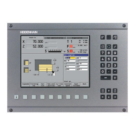
HEIDENHAIN MANUALPLUS 4110 Technical Manual (746 pages)
Brand:
HEIDENHAIN
| Category:
Control Systems
| Size: 16 MB
Table of Contents
Update Information
3
General Information
3
Table of Contents
5
Introduction
7
General Information
7
Component Overview of Manualplus 4110
9
Brief Description
12
Hardware
18
Designation of the Logic Unit
18
Software
19
Designation of the Software
19
PLC Software
19
Software Exchange
20
Data Backup
26
Configurations
27
Software Releases
28
Mounting and Electrical Installation
31
General Information
31
Degrees of Protection
31
Electromagnetic Compatibility
31
Shipping Brace of the Hard Disk
32
Environmental Conditions
33
Heat Generation and Cooling
33
Humidity
34
Mechanical Vibration
34
Mounting Attitude le 412 M, UV XXX, um XXX
35
Mounting Position of Screen
36
Connection Overview
37
Power Supply for the Logic Unit-The UV 105 Power Module
38
Supply Voltage for PLC Outputs
41
Supply Voltage for PLC Outputs on the le
41
Supply Voltage for PLC Outputs on the PL 4Xxb
42
Supply Voltage for Analog Inputs on PL 410B
43
Power Supply for Control-Is-Ready Signal
44
Axis-Specific Drive Controller Enabling
45
Encoder Connections
46
General Information
46
Input from Position Encoder (External Position Encoder)
47
Speed (Rotary) Encoder Input
48
Motor Power Stage Connection
50
BFT 121G Visual Display and Keyboard Unit
51
Machine Operating Panel
58
Analog Nominal Value Output
59
Switching Inputs 24 VDC (PLC)
60
Input Signals and Addresses
60
PLC Inputs on the PL 410B
62
PLC Inputs on the PL 405B
63
Switching Outputs 24 VDC (PLC)
64
PLC Input/Output Unit PL 4Xx B
67
Analog Input
70
Data Interfaces
74
Handwheels
78
Dimensions
79
Basic Circuit Diagrams
85
Basic Circuit Diagram for le 412 M Modular Regenerative HEIDENHAIN Inverter
85
Basic Circuit Diagram for le 412 M with UE 2Xxb HEIDENHAIN Compact Inverter
86
Basic Circuit Diagram for le 412 M with UR 2Xx Regenerative HEIDENHAIN Compact Inverter
87
Cable Overviews
88
Cable Overview for le 412 M Modular Regenerative HEIDENHAIN Inverter
88
Cable Overview for le 412 M with HEIDENHAIN Compact Inverter UE 2Xxb
89
Cable Overview for le 412 M with UE 2Xx Regenerative HEIDENHAIN Compact Inverters
90
Cable Overview le 412 M - Accessories
91
Overview of Control Parameters
123
Machine Integration
142
Machine Parameters
142
Logical Axis and Spindle Numbers
144
Editing the Bitsets
145
Parameter Transfer
146
Data Backup
147
General Machine Parameters
148
Identifying the Configuration, Machine Dimensions
148
Setting the Position Display
149
Configuration
151
General Configuration
151
Configuring the Slides
156
Parameters for Power Modules and Motors
160
Linear and Rotary Axis Configuration
171
Configuring Spindles
179
Configuring C Axes
186
Configuring the Tool Carrier
189
Configuring a Driven Tool
190
Control Loops
191
Digital Drive Control
192
Control Loops for Linear Axes
205
Control Loops for Spindles
218
Control Loops for C Axes
230
Compensations
238
Backlash Compensation
238
Screw-Pitch-Error and Angle Compensation
241
Misalignment Compensation
244
Special Functions
245
Calculate the Contour Velocity Profile (Look-Ahead)
245
Real-Time Coupling Functions
250
General Information
250
Defining Basic Operations
251
G Functions
255
Examples
257
Conversions
259
Control Parameters
261
Integrated Servicing Tools
269
Integrated Oscilloscope
269
Commissioning
280
Notes on Initial Operation
280
Parameter List for Initial Operation
282
Commissioning
284
CNC PILOT Block Diagram
302
PLC Programming
307
Individual Recording
358
Trigger Threshold
358
Load Two's Complement (L-)
383
Load Byte (Lb)
384
Load Double Word (Ld)
385
Assign Byte (B=)
388
Assign Word (W=)
388
Assign Not (=N)
390
Reset Not (Rn)
394
Remainder (Mod)
411
Exclusive or Not (Xon )
422
Shift Left
429
Shift Right
430
Push Data Onto the Data Stack (Ps)
434
Pull Data from the Data Stack (Pl)
435
Jump if Logic Accumulator = 1 (Jpt)
439
Call Module (CM)
440
Call Module if Logic Accumulator = 0 (Cmf)
441
End of Module, End of Program (Em)
442
Load String (L)
448
Equal to Command for String Processing
451
Not Equal Command for String Processing
452
PLC Parameters
650
Data Structure
668
Serial Interface
719
Ethernet Interface
728
Data Formats
732
Advertisement
HEIDENHAIN MANUALPLUS 4110 Manual (157 pages)
Brand:
HEIDENHAIN
| Category:
Control Panel
| Size: 3 MB
Table of Contents
Contents
3
Axis Directions
5
Reference Points
5
Traverse Motions
5
Tool in Front of or Behind the Workpiece
6
The Coordinate System
7
Two-Dimensional Coordinate System
7
C Axis
7
Accuracy
7
Tool-Tip Radius Compensation (TRC)
8
Feed Rate
9
Spindle Speed
9
Constant Spindle Speed
9
Constant Cutting Speed
9
Data Input Keypad
11
Soft Keys as Toggle Switches
13
Menu Selection (9-Field Box)
13
Soft Keys
13
Machine Data Display
14
Position Display
14
Display of X and Z Position
14
Distance-To-Go Display
14
Feed Rate Display Element
15
Set the Feed Rate
15
Feed Rate Display
15
Protection Zone Status
15
Spindle Display Element
16
Display for Positioning of Spindle
16
Driven Tool
16
Setting the Cutting Speed or Spindle Speed
16
Tool Display Element
17
One Tool Holder (Two-Digit T Display)
17
Turret or Automatic Tool Changer (Four-Digit T Display)
17
Switching on the Machine
18
Axis and Spindle Enabling
18
Sequence for Reference Run
19
Traversing the Reference Marks
19
Confirm Tool
20
Switching the Operating Mode
21
Error Messages and PLC Status Information
22
Processing Error Messages
22
Processing PLC Status Displays
22
Switching between the Error Window and the PLC Status Display
22
Switching the Manualplus 4110 off
23
Tool Measurement
25
Creating Tool T1
25
Tool Data
25
Specify the Position in the Tool Manager
26
Enter the Tool Data
26
Enter the Tool Description
27
Overview of Tool Data T1
28
Create Tool T2 by Copying
29
Copying
29
Assume Tool Data and Specify the Position in the Tool Manager
29
Tool Orientation WO: 1
30
Adapt Tool Data
30
Overview of Tool Data T2
30
Tool Angle A: 93
30
Tip Angle B
30
Wear Compensation DX in X: 0 MM Wear Compensation DZ in Z: 0 MM
30
Adapt the Tool Data
32
Setup Dimension Z in Z: 0 MM
37
Tool Orientation wo
37
Wear Compensation DX in X: 0 MM Wear Compensation DZ in Z: 0 MM
37
Machining Direction MD M3=3, M4=4
38
Prepare the Machine
41
Entering the Machine Data
41
Specify the Workpiece Datum
43
Facing a Surface
44
Setting Dimensions for T1
45
Call the “Measure Tool” Function
45
Producing the Measuring Diameter
46
Enter the Setting Dimensions
46
Determine Setting Dimensions for T2
47
Activate Tool T2
47
Touch the Measuring Diameter with the Tool
49
Touch the End Face with the Tool
49
Activate Tool T6
50
Setting Dimensions for T6
50
Entries and Assumed Machine Data
51
Setting Dimensions for T8
53
Activate Tool T8
53
Setting Dimensions for T10
56
Activate Tool T10
56
Machine Setup
59
Set the Workpiece Datum
61
Setting the Protection Zone
63
Approach the Protection Zone
64
Defining the Tool Change Position
65
Approach the Tool Change Position
66
“Threaded Stud” Example Program
67
Creating a Cycle Program
68
Program the “Icp–Longitudinal Cutting” Cycle
71
Assume the Tool and Technology Data from the Tool File
72
Contour Element 1 (Chamfer)
73
Call the ICP Editor
73
ICP Contour “Threaded Stud”
73
Describe the Contour Element
74
Contour Element 2 (Thread Undercut)
74
Contour Element 3 (Oblique Cut)
75
Contour Element 4 (Horizontal Line)
76
Contour Element 5 (Rounding)
77
Contour Element 6 (Vertical Line)
77
Contour Element 7 (Chamfer)
78
Contour Element 8 (Horizontal Line):
79
Contour Element 9 (Vertical Line)
79
Enter the Contour Name
80
Conclude and Test the “ICP Cutting Longitudinal” Cycle
82
Warnings
82
Run the Cycle
83
Program the “Approach Tool Change Position” Cycle
84
Create the “ICP Finishing Longitudinal” Cycle by Copying
86
Adapt the Cycle
87
Cycle Parameters
87
Run a Graphic Simulation of the Cycle
88
Create the “Threaded Stud” Cycle Program
88
Select Tool Compensation
90
Perform the Tool Compensation
90
Repeat the “ICP Finishing Longitudinal” Cycle
91
Program the “Threading Cycle”
93
Repeat the Last Thread Cut with the Corrected Tool
98
Create the “Matrix” Cycle Program
103
“Matrix” Example Program
103
Program the Cycle “ICP Cutting Transverse”
105
Program the Cycle “ICP Finishing Longitudinal”
108
Create the Matrix ICP Contour
113
Create the “Matrix” ICP Contour
114
Create the “Form Roll” Cycle Program
125
“Form Roll” Example Program
125
Program Cycle Blank—Bar/Tube
126
Run Graphic Simulation of Cycle
128
Create the ICP Contour “Form Roll”
141
Cutting Path Graphics
145
Wire Frame Graphics
145
Types of Simulation
145
Setting the Type of Simulation
146
Zoom Functions
147
Change the Image Section
147
Extend the View
148
Actions before Executing a Program
149
Activate Program Run
149
Select the New Program
150
Run a Graphic Simulation of the Program
151
Checking the Cycle
151
Run Cycles Individually
152
Run the Cycle Program (for each Cycle)
152
Interrupt the Program Run
153
Initial Situation
153
Tool Compensation
153
Measure the Workpiece
154
Entering Tool Compensation Values
154
Repeat the Finishing Cycle with the Corrected Tool
155
Advertisement
Related Products
HEIDENHAIN LS 4 7C Series
HEIDENHAIN ECN 425 EnDat22
HEIDENHAIN EQN 437 EnDat22
HEIDENHAIN MANUALPLUS 620
Heidenhain 548431-05
HEIDENHAIN ITNC 530 - 6-2010 DIN-ISO PROGRAMMING
HEIDENHAIN ITNC 530 - CYCLE PROGRAMMING
HEIDENHAIN ITNC 530 - PILOT SMART NC
HEIDENHAIN iTNC 530 E
HEIDENHAIN ND 1100 - V2.15.0 GUIDE
HEIDENHAIN Categories
Media Converter
Measuring Instruments
Industrial Equipment
Control Systems
Control Unit
More HEIDENHAIN Manuals
Login
Sign In
OR
Sign in with Facebook
Sign in with Google
Upload manual
Upload from disk
Upload from URL