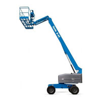
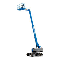
Sign In
Upload
Manuals
Brands
Genie Manuals
Lifting Systems
S-80
Genie S-80 Manuals
Manuals and User Guides for Genie S-80. We have
13
Genie S-80 manuals available for free PDF download: Service Manual, Service And Repair Manual, Maintenance Manual, Operator's Manual, Operator's Manual Supplement
Genie S-80 Service Manual (359 pages)
Brand:
Genie
| Category:
Boom Lifts
| Size: 46.21 MB
Table of Contents
Introduction
2
Find a Manual for this Model
2
Revision History
3
Serial Number Legend
5
Safety Rules
6
Table of Contents
8
Specifications
21
Machine Specifications
21
Performance Specifications
22
Hydraulic Oil Specifications
22
Hydraulic Component Specifications
25
Manifold Component Specifications
26
Continental TME27 Engine Specifications
27
Deutz Td2011L04I Engine Specifications
28
Deutz TD 2.9 Engine Specifications
29
Machine Torque Specifications
32
Hydraulic Hose and Fitting Torque Specifications
33
Torque Procedure
34
February
35
Scheduled Maintenance Procedures
36
Pre-Delivery Preparation Report
39
Maintenance Inspection Report
40
Checklist a Procedures
42
Inspect the Manuals and Decals
42
Perform Pre-Operation Inspection
43
Perform Function Tests
43
A-5 Perform Engine Maintenance – Deutz Models
44
Test the Oscillate Axle
45
Check the High Pressure Hydraulic Filter Condition Indicator
46
Perform 30-Day Service
46
Perform Engine Maintenance - Continental Models
47
Grease the Turntable Rotation Bearing and Rotate Gear
48
Replace the Drive Hub Oil
48
Checklist B Procedures
49
Inspect the Batteries
49
Inspect the Electrical Wiring
50
Check the Exhaust System
52
Inspect the Engine Air Filter
53
Perform Engine Maintenance - Continental Models
54
Perform Engine Maintenance - Perkins Models
54
Confirm the Proper Brake Configuration
55
Inspect the Tires, Wheels and Lug Nut Torque
55
Check the Drive Hub Oil Level and Fastener Torque
56
Check the Oscillate Directional Valve Linkage
57
Test the Ground Control Override
57
Test the Platform Self-Leveling
58
Test the Engine Idle Select
58
February
58
Test the Drive Brakes
60
Test the Drive Speed - Stowed Position
61
Test the Drive Speed - Raised or Extended Position
61
Inspect the Fuel and Hydraulic Tank Cap Venting Systems
63
Perform Hydraulic Oil Analysis
64
Inspect the Boom Extend/Retract Cables
65
Test the Emergency Power System
67
Checklist C Procedures
68
Perform Engine Maintenance - Continental Models
68
Perform Engine Maintenance - Deutz Models
68
Perform Engine Maintenance - Perkins Models
69
Replace the Engine Air Filter Element
69
Check and Adjust the Engine RPM
70
Grease the Platform Overload Mechanism (if Equipped)
72
Test the Platform Overload System (if Equipped)
72
Check the Safety Envelope Limit Switches and Angle Sensor, S80X
74
February
75
Checklist D Procedures
77
Check the Boom Wear Pads
77
Check the Free-Wheel Configuration
78
Check the Turntable Rotation Bearing Bolts
80
Inspect for Turntable Bearing Wear
81
Replace the Hydraulic Filters
82
Replace the Drive Hub Oil
83
Perform Engine Maintenance - Continental Models
85
Perform Engine Maintenance - Deutz Models
85
Perform Engine Maintenance - Perkins Models
86
Inspect the Boom Extend/Retract Cables
86
Checklist E Procedures
88
Test or Replace the Hydraulic Oil
88
Perform Engine Maintenance - Perkins Models
90
Perform Engine Maintenance - Deutz Models
90
Perform Engine Maintenance - Perkins Models
91
Perform Cooling System Maintenance - Perkins 404F Models
91
Remove and Inspect the Boom Extend/Retract Cables
92
Cable Replacement Criteria
94
Repair Procedures
95
Platform Controls
97
ALC-500 Circuit Board
97
How to Remove the ALC-500 Circuit Board
97
Joysticks
98
How to Adjust the Joystick Max-Out Setting
99
How to Adjust the Joystick Ramp Rate Setting
100
How to Adjust the Joystick Threshold Setting
101
How to Calibrate the Boom Angle Sensor
102
Platform Components
104
Platform
104
How to Bleed the Slave Cylinder
105
Platform Leveling Slave Cylinder
105
Platform Rotator
106
How to Remove the Platform Rotator
106
How to Bleed the Platform Rotator
107
Platform Overload System
108
Jib Boom Components
111
Jib Boom
111
Jib Boom Lift Cylinder
112
Boom Components
113
Cable Track
113
How to Remove the Cable Track, S-80
113
How to Repair the Cable Track
115
Boom
115
How to Shim the Boom
115
How to Remove the Boom
116
Boom Lift Cylinder
118
Boom Extension Cylinder
120
Boom Extend/Retract Cables
122
How to Adjust the Extend/Retract Cables
123
How to Replace the Boom Extend/Retract Cables
124
Platform Leveling Master Cylinder
126
Engines
127
RPM Adjustment
127
Flex Plate
127
How to Remove the Flex Plate
127
How to Install the Flex Plate
130
How to Install the Pump and Bell Housing Assembly
131
Ground Controls
132
Control Relays
132
Hydraulic Pumps
133
Function Pump
133
Drive Pump
134
How to Prime the Pump
135
Manifolds
136
Function Manifold Components
136
Valve Adjustments - Function Manifold
138
How to Adjust the System Relief Valve
138
How to Adjust the Boom down Relief Valve
138
How to Adjust the Boom Extend Relief Valve
139
Brake/Two-Speed Manifold Components
140
Turntable Rotation Manifold Components
141
Platform Rotate Manifold Components
142
Platform Manifold Components, S-80
143
Platform Manifold Components, S-85
144
2WD Traction Manifold Components
145
4WD Traction Manifold Components
146
Drive Oil Diverter Manifold Components (Welder Option)
148
Valve Adjustments - Traction Manifold
149
Valve Coils
150
Valve Coil Resistance Specifications
150
Advertisement
Genie S-80 Service Manual (353 pages)
Brand:
Genie
| Category:
Lifting Systems
| Size: 4.66 MB
Table of Contents
Table of Contents
9
Introduction
2
Serial Number Information
2
Serial Number Legend
5
Safety Rules
7
Table of Contents
9
Table of Contents
20
Machine Specifications
21
Hydraulic Oil Specifications
22
Performance Specifications
22
Hydraulic Component Specifications
23
Valve Coil Resistance Specifications
24
Continental TME27 Engine Specifications
25
Deutz Td2011L04I Engine Specifications
26
Perkins 804D-33 Engine Specifications
27
Machine Torque Specifications
28
Manifold Component Specifications
28
Hydraulic Hose and Fitting Torque Specifications
29
Pre-Delivery Preparation
33
Maintenance Inspection Report
35
Checklist a Procedures
37
Inspect the Manuals and Decals
37
Perform Engine Maintenance
38
Perform Pre-Operation Inspection
38
Perform Function Tests
39
Test the Oscillate Axle
39
Check the High Pressure Hydraulic Filter Condition Indicator
40
Perform 30 Day Service
40
Inspect the Fuel Filter/Water Separator - Diesel Models
41
Perform Engine Maintenance - Deutz and Continental Models
41
Grease the Turntable Rotation Bearing and Rotate Gear
43
Perform Engine Maintenance
44
Replace the Drive Hub Oil
45
Perform Engine Maintenance - Perkins Models
47
Checklist B Procedures
48
Inspect the Battery(S)
48
Inspect the Electrical Wiring
49
Check the Exhaust System
51
Test the Key Switch
51
Inspect the Engine Air Filter
52
Check the Oil Cooler and Cooling Fins - Deutz Models
53
Confirm the Proper Brake Configuration
54
Inspect the Tires, Wheels and Lug Nut Torque
54
Check the Drive Hub Oil Level and Fastener Torque
55
Check and Adjust the Engine RPM
56
Check the Oscillate Directional Valve Linkage
58
Perform Engine Maintenance
58
Test the Ground Control Override
59
Test the Platform Self-Leveling
59
Test the Engine Idle Select Operation
60
Test the Fuel Select Operation - Gasoline/Lpg Models
61
Test the Drive Enable System
62
Test the Drive Brakes
63
Test the Drive Speed - Stowed Position
63
Test the Drive Speed - Raised or Extended Position
64
Test the Alarm Package (if Equipped) and the Descent Alarm
65
Inspect the Fuel and Hydraulic Tank Cap Venting Systems
66
Inspect the Boom Extend/Retract Cables
67
Perform Hydraulic Oil Analysis
67
Checklist C Procedures
69
Grease the Platform Overload Mechanism (if Equipped)
69
Test the Platform Overload System (if Equipped)
70
Replace the Fuel Filter/Water Separator Element - Diesel Models
73
Check the Safety Envelope Limit Switches and Angle Sensor, S-80X
75
Check the Boom Wear Pads
78
Checklist D Procedures
78
Check the Free-Wheel Configuration
79
Check the Turntable Rotation Bearing Bolts
80
Inspect the Turntable Bearing Wear
81
Perform Engine Maintenance
83
Replace the Drive Hub Oil
84
Perform Engine Maintenance - Deutz Models
86
Checklist E Procedures
87
Test or Replace the Hydraulic Oil
87
Perform Engine Maintenance - Deutz and Perkins Models
89
Perform Engine Maintenance - Perkins Models
89
Remove and Replace the Boom Extend/Retract Cables
90
Circuit Board
92
Platform Controls
92
Joysticks
93
Platform
99
Platform Components
99
Platform Leveling Slave Cylinder
100
Platform Rotator
101
Calibrate the Platform Overload System
103
Jib Boom
106
Jib Boom Components
106
Jib Boom Lift Cylinder
107
Boom Components
108
Cable Track
108
Boom
111
Boom Lift Cylinder
114
Boom Extension Cylinders
115
Boom Extend/Retract Cables
118
Platform Leveling Master Cylinder
122
Flex Plate
123
RPM Adjustment
123
Control Relays
128
Ground Controls
128
Function Pump
129
Hydraulic Pumps
129
Drive Pump
130
Function Manifold Components
132
Valve Adjustments - Function Manifold
134
Brake/Two-Speed Manifold Components
136
Turntable Rotation Manifold Components
137
Platform Rotate Manifold Components
138
Platform Manifold Components, S-80
139
Platform Manifold Components, S-85
140
2WD Traction Manifold Components
141
4WD Traction Manifold Components (before Serial Number 8581)
143
4WD Traction Manifold Components (after Serial Number 8580)
145
Drive Oil Diverter Manifold Components (Welder Option)
147
Valve Adjustments - Traction Manifold
148
Valve Coils
149
Fuel and Hydraulic Tanks
151
Fuel Tank
151
Hydraulic Tank
152
Turntable Rotation Components
154
Turntable Rotation Drive Hub Assembly
154
2 WD Steer Axle Components
157
Yoke and Hub
157
Steer Cylinder
158
4 WD Steer Axle Components
159
Yoke and Drive Hub
159
Drive Motor
160
Drive Hub
161
Steer Cylinders
161
Non-Steer Axle Components
162
Drive Motor
162
Drive Hub
162
Oscillating Axle Components
163
Oscillate Axle Cylinders
163
Oscillate Directional Valve
164
Fault Codes - Control System
168
Electrical Symbols Legend
180
Hydraulic Symbols Legend
181
Connector Pin Legend - View 1
184
Connector Pin Legend - View 2
185
Deutz Td2011L04I Models
188
Platform Control Box Wiring Diagram, S-80 and S-85 (ANSI / CSA / as Deutz Td2011L04I Models
196
Electrical Schematic, S-80 and S-85 (CE Deutz Td2011L04I Models (before Serial Number 8111)
200
Ground Control Box Terminal Strip Wiring Diagram, S-80 and S-85 (CE Deutz Td2011L04I Models (before Serial Number 8111)
204
Ground Control Box Switch Panel Wiring Diagram, S-80 and S-85 (CE Deutz Td2011L04I Models (before Serial Number 8111)
205
Platform Control Box Wiring Diagram, S-80 and S-85 (CE)
207
Platform Control Box Wiring Diagram, S-80 and S-85 (CE Deutz Td2011L04I Models (before Serial Number 8111)
208
Platform Control Box Switch Panel Wiring Diagram, S-80 and S-85 (CE Deutz Td2011L04I Models (before Serial Number 8111)
209
Deutz Td2011L04I Models (after Serial Number 8110)
211
Deutz Td2011L04I Models (after Serial Number 8110)
212
Electrical Schematic, S-80 and S-85 (CE Deutz Td2011L04I Models (after Serial Number 8110)
212
Ground Control Box Terminal Strip Wiring Diagram, S-80 and S-85 (CE Deutz Td2011L04I Models (after Serial Number 8110)
216
Ground Control Box Switch Panel Wiring Diagram, S-80 and S-85 (CE Deutz Td2011L04I Models (after Serial Number 8110)
217
Deutz Td2011L04I Models (after Serial Number 8110)
220
Platform Control Box Switch Panel Wiring Diagram, S-80 and S-85 (CE Deutz Td2011L04I Models (after Serial Number 8110)
221
Electrical Schematic, S-80X
223
Deutz Td2011L04I Models
223
Ground Control Box Terminal Strip Wiring Diagram, S-80X
227
Deutz Td2011L04I Models
227
Ground Control Box Switch Panel Wiring Diagram, S-80X
229
Deutz Td2011L04I Models
229
Platform Control Box Wiring Diagram, S-80X
231
Deutz Td2011L04I Models
231
Deutz Td2011L04I Models
232
Electrical Schematic, S-80 and S-85 (ANSI / CSA / AS)
235
Perkins 804D-33 Models
235
Electrical Schematic, S-80 and S-85 (ANSI / CSA / as Perkins 804D-33 Models
236
And S-85 (ANSI / CSA / AS), Perkins 804D-33 Models
239
Perkins 804D-33 Models
244
Electrical Schematic, S-80 and S-85 (CE)
247
Perkins 804D-33 Models (before Serial Number 8111)
247
Electrical Schematic, S-80 and S-85 (CE Perkins 804D-33 Models (before Serial Number 8111)
248
Perkins 804D-33 Models (before Serial Number 8111)
252
Ground Control Box Switch Panel Wiring Diagram, S-80 and S-85 (CE Perkins 804D-33 Models (before Serial Number 8111)
253
Platform Control Box Wiring Diagram, S-80 and S-85 (CE Perkins 804D-33 Models (before Serial Number 8111)
256
Electrical Schematic, S-80 and S-85 (CE Perkins 804D-33 Models (after Serial Number 8110)
260
Ground Control Box Terminal Strip Wiring Diagram, S-80 and S-85 (CE Perkins 804D-33 Models (after Serial Number 8110)
264
Ground Control Box Switch Panel Wiring Diagram, S-80 and S-85 (CE Perkins 804D-33 Models (after Serial Number 8110)
265
Platform Control Box Wiring Diagram, S-80 and S-85 (CE Perkins 804D-33 Models (after Serial Number 8110)
268
Platform Control Box Switch Panel Wiring Diagram, S-80 and S-85 (CE Perkins 804D-33 Models (after Serial Number 8110)
269
Electrical Schematic, S-80X Perkins 804D-33 Models
272
Ground Control Box Terminal Strip Wiring Diagram, S-80X Perkins 804D-33 Models
276
Platform Control Box Wiring Diagram, S80X Perkins 804D-33 Models
280
Platform Control Box Switch Panel Wiring Diagram, S80X Perkins 804D-33 Models
281
Continental TME27 Models
284
Ground Control Box Terminal Strip Wiring Diagram S-80 and S-85 (ANSI / CSA / AS), Continental TME27 Models
288
Platform Control Box Wiring Diagram, S-80 and S-85 (ANSI / CSA / as Continental TME27 Models
292
Electrical Schematic, S-80 and S-85 (CE Continental TME27 Models (before Serial Number 8111)
296
Ground Control Box Terminal Strip Wiring Diagram, S-80 and S-85 (CE Continental TME27 Models (before Serial Number 8111)
300
Ground Control Box Switch Panel Wiring Diagram, S-80 and S-85 (CE Continental TME27 Models (before Serial Number 8111)
301
Platform Control Box Wiring Diagram, S-80 and S-85 (CE Continental TME27 Models (before Serial Number 8111)
304
Platform Control Box Switch Panel Wiring Diagram, S-80 and S-85 (CE Continental TME27 Models (before Serial Number 8111)
305
Electrical Schematic, S-80 and S-85 (CE Continental TME27 Models (after Serial Number 8110)
308
Ground Control Box Terminal Strip Wiring Diagram, S-80 and S-85 (CE Continental TME27 Models (after Serial Number 8110)
312
Ground Control Box Switch Panel Wiring Diagram, S-80 and S-85 (CE Continental TME27 Models (after Serial Number 8110)
313
Continental TME27 Models (after Serial Number 8110)
316
Platform Control Box Switch Panel Wiring Diagram, S-80 and S-85 (CE Continental TME27 Models (after Serial Number 8110)
317
Electrical Schematic, S-80X Continental TME27 Models
320
Ground Control Box Terminal Strip Wiring Diagram, S-80X Continental TME27 Models
324
Platform Control Box Wiring Diagram, S-80X Continental TME27 Models
328
Continental TME27 Engine Harness
332
Platform Level Cutout, CTE Option
333
Continental Options Schematic
336
Deutz and Perkins Options Schematic
337
Kw Hydraulic Generator Wiring Diagram
340
Kw Hydraulic Generator Electrical Schematic
341
Belt Driven Generator Option
344
Relay and Fuse Panel Legend
345
Hydraulic Schematic, 2WD Models
348
Hydraulic Schematic, 4WD Models
349
Kw Hydraulic Generator Hydraulic Schematic
351
Genie S-80 Service And Repair Manual (301 pages)
from S80/85/80X15-12264
Brand:
Genie
| Category:
Boom Lifts
| Size: 30.48 MB
Table of Contents
Introduction
2
Find a Manual for this Model
2
September
2
Serial Number Legend
4
Safety Rules
5
Table of Contents
7
Specifications
15
Machine Specifications
15
Performance Specifications
16
Hydraulic Component Specifications
18
Manifold Component Specifications
19
Continental TME27 Engine Specifications
20
Deutz Td2011L04I Engine Specifications
21
Deutz TD 2.9 Engine Specifications
22
Machine Torque Specifications
25
Hydraulic Hose and Fitting Torque Specifications
26
Torque Procedure
27
September
28
Repair Procedures
29
Section 3 Repair Procedures
29
About this Section
30
Platform Controls
31
ALC-500 Circuit Board
31
How to Remove the ALC-500 Circuit Board
31
Joysticks
32
How to Adjust the Joystick Max-Out Setting
33
How to Adjust the Joystick Ramp Rate Setting
34
How to Adjust the Joystick Threshold Setting
35
How to Calibrate the Boom Angle Sensor
36
Platform Components
38
Platform
38
How to Remove the Platform Leveling Slave Cylinder
39
How to Bleed the Slave Cylinder
39
Platform Rotator
40
How to Remove the Platform Rotator
40
How to Bleed the Platform Rotator
41
Platform Overload System
42
Jib Boom Components
45
Jib Boom
45
Jib Boom Lift Cylinder
46
Boom Components
47
Cable Track
47
How to Remove the Cable Track, S-80
47
How to Repair the Cable Track
49
Boom
49
How to Shim the Boom
49
How to Remove the Boom
50
Boom Lift Cylinder
52
Boom Extension Cylinder
54
Boom Extend/Retract Cables
56
How to Adjust the Extend/Retract Cables
56
How to Replace the Boom Extend/Retract Cables
58
Platform Leveling Master Cylinder
60
Engines
61
RPM Adjustment
61
Flex Plate
61
How to Remove the Flex Plate
61
How to Install the Flex Plate
64
How to Install the Pump and Bell Housing Assembly
65
Ground Controls
66
Control Relays
66
Hydraulic Pumps
67
Function Pump
67
Drive Pump
68
How to Prime the Pump
69
Manifolds
70
September
70
Function Manifold
72
Valve Adjustments - Function Manifold
72
How to Adjust the System Relief Valve
72
How to Adjust the Boom down Relief Valve
72
How to Adjust the Boom Extend Relief Valve
73
Brake/Two-Speed Manifold Components
74
Turntable Rotation Manifold Components
75
Platform Rotate Manifold Components
76
Platform Manifold Components, S-80
77
Platform Manifold Components, S-85
78
2WD Traction Manifold Components
79
4WD Traction Manifold Components
80
Drive Oil Diverter Manifold Components (Welder Option)
82
Valve Adjustments - Traction Manifold
83
Valve Coils
84
Valve Coil Resistance Specifications
84
How to Test a Coil Diode
85
Fuel and Hydraulic Tanks
86
Fuel Tank
86
Hydraulic Tank
87
Turntable Rotation Components
89
Turntable Rotation Drive Hub Assembly
89
How to Remove the Turntable Rotation Drive Hub Assembly
89
How to Remove the Turntable Rotation Hydraulic Motor
90
How to Adjust the Turntable Rotation Gear Backlash
91
September
92
Steer Axle Components
93
Yoke and Drive Hub
93
Drive Motors
94
Drive Hubs
94
Steer Cylinders
95
Non-Steer Axle Components
96
Drive Motor
96
Drive Hub
96
Oscillating Axle Components
97
Oscillate Axle Cylinders
97
Oscillate Directional Valve
98
How to Adjust the Oscillate Relief Valve
98
How to Set up the Directional Valve Linkage
99
Fault Codes
101
Section 4 Fault Codes
101
Control System Fault Codes
102
How to Retrieve Control System Fault Codes
102
Control System Fault Codes
103
Fault Code Display - Deutz and Perkins Models
107
How to Retrieve Active Engine Fault Codes Deutz D 2.9 L4 and Perkins 404F-22 Models
107
Fault Code Display - Flashing and Solid Led's Deutz D 2.9 L4 and Perkins 404F-22 Models
108
Deutz D 2.9 L4 and Perkins 404F-22 Models
109
Soft Key Functions and Icons - Deutz D 2.9 L4 and Perkins 404F-22 Models
109
Main Menu Structure - Deutz D 2.9 L4 Models
110
Main Menu Structure - Perkins 404F-22 Models
111
Advertisement
Genie S-80 Service And Repair Manual (305 pages)
Brand:
Genie
| Category:
Boom Lifts
| Size: 28.52 MB
Table of Contents
October
2
Find a Manual for this Model
2
October
4
Serial Number Legend
4
Safety Rules
5
Table of Contents
7
Specifications
17
Machine Specifications
17
Performance Specifications
18
Hydraulic Component Specifications
21
Manifold Component Specifications
22
Continental TME27 Engine Specifications
23
Deutz Td2011L04I Engine Specifications
24
Deutz TD 2.9 Engine Specifications
25
Machine Torque Specifications
28
Hydraulic Hose and Fitting Torque Specifications
29
Torque Procedure
30
October
31
Repair Procedures
32
Section 3 Repair Procedures
32
About this Section
33
Platform Controls
34
ALC-500 Circuit Board
34
How to Remove the ALC-500 Circuit Board
34
Joysticks
35
How to Adjust the Joystick Max-Out Setting
36
How to Adjust the Joystick Ramp Rate Setting
37
How to Adjust the Joystick Threshold Setting
38
How to Calibrate the Boom Angle Sensor
39
Platform Components
41
Platform
41
How to Remove the Platform Leveling Slave Cylinder
42
How to Bleed the Slave Cylinder
42
Platform Rotator
43
How to Remove the Platform Rotator
43
How to Bleed the Platform Rotator
44
Platform Overload System
45
Jib Boom Components
48
Jib Boom
48
Jib Boom Lift Cylinder
49
Boom Components
50
Cable Track
50
How to Remove the Cable Track, S-80
50
How to Repair the Cable Track
52
Boom
52
How to Shim the Boom
52
How to Remove the Boom
53
Boom Lift Cylinder
55
Boom Extension Cylinder
57
Boom Extend/Retract Cables
59
How to Adjust the Extend/Retract Cables
59
How to Replace the Boom Extend/Retract Cables
61
Platform Leveling Master Cylinder
63
Primary Boom Angle Sensor, S-80X
64
Engines
66
RPM Adjustment
66
Flex Plate
66
How to Remove the Flex Plate
66
How to Install the Flex Plate
69
How to Install the Pump and Bell Housing Assembly
70
Ground Controls
71
Control Relays
71
Hydraulic Pumps
72
Function Pump
72
Drive Pump
73
How to Prime the Pump
74
Manifolds
75
Function Manifold
75
October
75
Valve Adjustments - Function Manifold
77
How to Adjust the System Relief Valve
77
How to Adjust the Boom down Relief Valve
77
How to Adjust the Boom Extend Relief Valve
78
Brake/Two-Speed Manifold Components
79
Turntable Rotation Manifold Components
80
Platform Rotate Manifold Components
81
Platform Manifold Components, S-80
82
Platform Manifold Components, S-85
83
2WD Traction Manifold Components
84
4WD Traction Manifold Components
85
Drive Oil Diverter Manifold Components (Welder Option)
87
Valve Adjustments - Traction Manifold
88
Valve Coils
89
Valve Coil Resistance Specifications
89
Fuel and Hydraulic Tanks
91
Fuel Tank
91
Hydraulic Tank
92
October
93
Turntable Rotation Components
94
Turntable Rotation Drive Hub Assembly
94
How to Remove the Turntable Rotation Drive Hub Assembly
94
October
94
How to Remove the Turntable Rotation Hydraulic Motor
95
How to Adjust the Turntable Rotation Gear Backlash
96
Steer Axle Components
98
Yoke and Drive Hub
98
Drive Motors
99
Drive Hubs
99
Steer Cylinders
100
Non-Steer Axle Components
101
Drive Motor
101
Drive Hub
101
Oscillating Axle Components
102
Oscillate Axle Cylinders
102
Oscillate Directional Valve
103
How to Adjust the Oscillate Relief Valve
103
How to Set up the Directional Valve Linkage
104
Fault Codes
105
Section 4 Fault Codes
105
Control System Fault Codes
106
How to Retrieve Control System Fault Codes
106
Control System Fault Codes
107
Fault Code Display - Deutz and Perkins Models
111
How to Retrieve Active Engine Fault Codes Deutz D 2.9 L4 and Perkins 404F-22 Models
111
22 Models
111
Soft Key Functions and Icons - Deutz D 2.9 L4 and Perkins 404F-22 Models
113
October
113
Main Menu Structure - Deutz D 2.9 L4 Models
114
Main Menu Structure - Perkins 404F-22 Models
115
Genie S-80 Service Manual (214 pages)
Brand:
Genie
| Category:
Boom Lifts
| Size: 2.83 MB
Table of Contents
Introduction
2
Safety Rules
3
Table of Contents
5
Specifications
13
Machine Specifications
13
Performance Specifications
14
Hydraulic Specifications
15
Bolt Torque Specifications
16
Ford LSG 423 Engine Specifications
17
Deutz F4L Engine Specifications
20
Scheduled Maintenance Inspections
21
Maintenance Inspection Report
27
Scheduled Maintenance Procedures
29
Inspect the Manuals
30
Inspect the Decals and Placards
30
Inspect for Damage, Loose or Missing Parts
30
Check the Engine Oil Level
31
Check the Engine Coolant Level - Gasoline/Lpg Models
31
Check for Fuel Leaks
31
Check the Hydraulic Oil Level
32
Check for Hydraulic Leaks
32
Check the Tire Pressure
33
Test the Extendable Axles
33
Test the Platform and Ground Controls
34
Test the Auxiliary Power Operation
34
Test the Tilt Sensor
35
Test the Limit Switches
36
Replace the Engine Oil and Filter - Gasoline/Lpg Models
38
Replace the Engine Air Filter
39
Check the Engine Belt(S)
40
Check the Radiator - Gasoline/Lpg Models
40
Check the Oil Cooler and Cooling Fins - Deutz Diesel Models
40
Check the Exhaust System
41
Check the Battery
42
Check the Hydraulic Tank Filter Condition Indicator
42
Inspect the Electrical Wiring
43
Inspect the Tires and Wheels
43
Confirm the Proper Brake Configuration
44
Check the Oil Level in the Torque Hubs
44
Check and Adjust the Engine Idle Mixture - Gasoline/Lpg Models
45
Check and Adjust the Engine RPM
45
Test the Key Switch
47
Test the Emergency Stop Buttons
48
Test the Ground Control Override
48
Test the Platform Self-Leveling
48
Test the Service Horn
49
Test the Foot Switch
49
Test the Engine Idle Select
49
Test the Fuel Select Operation - Gasoline/Lpg Models
50
Test the Drive Enable System
51
Test the Drive Brakes
51
Test the Drive Speed - Stowed Position
52
Test the Alarm Package - Optional Equipment
52
Perform Hydraulic Oil Analysis
53
Check the Hydraulic Limit Switch Linkage
53
Replace the Engine Oil and Filter - Deutz Diesel Models
54
Check the Boom Wear Pads
55
Check the Extendable Axle Wear Pads
55
Check the Turntable Rotation Bearing Bolts
55
Check the Free-Wheel Configuration
56
Grease the Turntable Rotation Bearing and Rotate Gear
57
Replace the Torque Hub Oil
57
Replace the Hydraulic Tank Filter
59
Replace the Drive Loop Hydraulic Filter
59
Replace the Diesel Fuel Filter - Deutz Diesel Models
60
Replace the Gasoline Fuel Filter - Gasoline/Lpg Models
60
Replace the PCV Valve - Gasoline/Lpg Models
62
Clean or Replace the Distributor Cap and Rotor - Gasoline/Lpg Models
62
Replace the Spark Plugs - Gasoline/Lpg Models
63
Check and Adjust the Air/Lpg Mixture - Gasoline/Lpg Models
64
Check and Adjust the Ignition Timing - Gasoline/Lpg Models
65
Check the Engine Valve Clearances - Deutz Diesel Models
65
Adjust the Turntable Rotation Gear Backlash
65
Test or Replace the Hydraulic Oil
66
Change or Recondition the Engine Coolant - Gasoline/Lpg Models
67
Change the Fuel Lines
69
Check the Engine Valve Clearance - Gasoline/Lpg Models
70
Check the Engine Cylinder Compression - Gasoline/Lpg Models
70
Clean the PCV Hoses and Fittings - Gasoline/Lpg Models
71
Check the Fuel Injection Pumps and Injectors - Deutz Diesel Models
72
Check the Toothed Belt - Deutz Diesel Models
72
Replace the Timing Belt - Gasoline/Lpg Models
72
Gasoline/Lpg Models
72
Gasoline/Lpg Models
78
Engine Cranks over but will Not Start - Deutz Diesel Models
85
Engine will Not Start on LPG, but will Start on Gasoline Gasoline/Lpg Models
88
Engine will Not Start on Gasoline, but will Start on LPG Gasoline/Lpg Models
90
Engine High Idle Inoperative - Gasoline/Lpg Models
92
Engine Low Idle Inoperative - Gasoline/Lpg Models
94
Engine High Idle Inoperative - Deutz Diesel Models
95
Engine Low Idle Inoperative - Deutz Diesel Models
97
All Functions Inoperative, Engine Starts and Runs
98
All Lift and Steer Functions Inoperative, Drive Functions Operational
99
Ground Controls Inoperative, Platform Controls Operate Normally
102
Platform Controls Inoperative, Ground Controls Operate Normally
103
Boom up Function Inoperative
104
Boom down Function Inoperative
106
Boom Extend Function Inoperative
108
Boom Retract Function Inoperative
110
Turntable Rotate Function Inoperative
111
Turntable Rotate Left Function Inoperative
113
Turntable Rotate Right Function Inoperative
114
All Platform Leveling Functions Inoperative
115
Platform Level up Function Inoperative
116
Platform Level down Function Inoperative
117
Platform Rotate Left Function Inoperative
118
Platform Rotate Right Function Inoperative
120
Drive Chassis Jack Function Inoperative
126
Steer Left Function Inoperative
128
Steer Right Function Inoperative
129
All Drive Functions Inoperative, All Other Functions Operate Normally
130
Drive Forward or Reverse Function Inoperative
133
Traction Function Inoperative
134
Machine will Not Drive at Full Speed
135
Machine Drives at Full Speed with Platform Raised or Extended
136
Drive Enable System Is Malfunctioning
137
Auxiliary Functions Inoperative
138
Electrical Symbols Legend
141
Electrical Schematic - Gasoline/Lpg Models
142
Ground Control Box Legend - Gasoline/Lpg Models
144
Relay Panel Legend - Gasoline/Lpg Models
145
Platform Control Box Legend - Gasoline/Lpg Models
146
Electrical Schematic - Diesel Models
147
Ground Control Box Legend - Diesel Models
149
Platform Control Box Legend - Diesel Models
150
Hydraulic Symbols Legend
151
2WD Hydraulic Schematic
152
4WD Hydraulic Schematic
153
Genie S-80 Maintenance Manual (182 pages)
Brand:
Genie
| Category:
Boom Lifts
| Size: 8.52 MB
Table of Contents
Table of Contents
9
Models Included in this Manual
3
Introduction
3
Identifying the Correct Procedure for Your Model
4
Find Additional Manuals for Your Model
4
Revision History
5
Safety Rules
7
Table of Contents
9
Performance Specifications
15
Function Speeds - S-100, S-105 and S-100HD
15
Function Speeds - S-120, S-125 and S-120HD
16
Function Speeds - All Other Models
17
Maintenance Manual October 2018 Performance Specifications
18
Jib Boom down
19
Jib Boom Rotate
19
Jib Boom up
19
Primary Boom Extend
19
Primary Boom Retract
19
Secondary Boom down
19
Secondary Boom up
19
Turntable Rotate
20
Platform Level (10° Range of Motion)
21
Platform Rotate
21
Drive Speeds
23
Ansi/Csa
25
Tires and Wheels
26
Torque Specifications
26
Trax Torque Specifications
27
Engine Operator and Maintenance Manuals
28
Engine Specifications
28
Deutz Engine Models
29
Perkins Engine Models
30
Ford Engine Models
32
Kubota Engine Models
32
GM Engine Models
33
Continental Engine Models
34
Cummins Engine Models
34
Hydraulic Relief Valves
35
Hydraulic Specifications
35
Hydraulic and Drive Hub Fluid Capacities
38
Hydraulic Oil Specifications
40
Hydraulic Hose and Fitting Torque Specifications
43
Torque Procedure
44
Introduction
46
Maintenance Procedures
46
Maintenance Schedule
48
Pre-Delivery Preparation Report
49
Scheduled - Quarterly October 2018 Maintenance Inspection Report - Booms
50
Scheduled Maintenance Inspection Report - Quarterly or Frequent
50
Boom(S) and Platform
51
Drive Chassis
51
Scheduled Maintenance Inspection Report - Annual
51
Turntable Mechanicals and Hydraulics
51
Programmed Maintenance Inspection Report - Booms
52
Commissioning Procedures
53
Perform 50 Hour Service
53
Perform Engine Maintenance - 50 Hours
53
Perform 150 Hour Service
54
Check for Open Bulletins and Owner Registration
55
Quarterly Maintenance Procedures
55
Battery Inspection
56
Inspect the Electrical Wiring
58
Inspect the Electrical Contactor - DC / Bi-Energy Models
59
Check the Exhaust System
60
Inspect the Tires, Wheels and Lug Nut Torque
60
Check the Generator Belts and Pulleys, Bi-Energy Models
61
Check the Oscillate Directional Valve Linkage (if Equipped)
62
Visual Inspection of the Hydraulic Oil
63
Inspect the Hydraulic Filters
64
Check and Adjust the Engine RPM
65
Test the Ground Control Override
70
Test the Alarm Package (if Equipped
71
Test the Alarm Package (if Equipped)
71
Test the Emergency Power System
72
Test the Engine Idle Select - Engine Models
72
Test the Engine Idle Select Operation
72
Test the Fuel Select Operation - Gasoline/Lpg Models
74
Inspect the Calibration Decal - ALC1000 Models
75
Test the Recovery Mode System - ALC-1000 Models
76
Test the Recovery System - ALC-1000 Models
76
Test the Platform Self-Leveling
77
Confirm the Proper Brake Configuration
78
Test the Drive Brakes
78
Test the Drive Speed - Raised or Extended Position
79
Test the Drive Speed - Stowed Position
79
Test the Drive Speed - Raised and Extended Position
80
Test the Drive Speed - Raised and Extended, ALC1000 Models
80
Sx-105Xc, Sx-125Xc, Sx-135Xc
82
Test the Turntable Level Sensor
82
XC, SX-125 XC, SX-135 XC, SX-150 and SX-180
82
Test the Secondary Boom Angle Sensor
84
Test the Secondary Boom Angle Sensor - Z-135/70 and ZX-135/70
84
Test the Primary Boom Angle Sensor - Z-135/70 and
86
Test the Primary Boom Angle Sensor - Z-135/70 and ZX-135/70
86
Test the Primary Boom Angle Sensor
89
XC, SX-125 XC, SX-135 XC, SX-150 and SX-180
89
Test the Safety Envelope Limit Switches
94
Test the Safety Envelope Limit Switches - Z-135/70, ZX-135/70, SX-105
94
Test the Primary Boom Angle Sensor
98
Test the Primary Boom Angle Sensor - Z-80/60
98
Test the Safety Envelope and Circuits
99
Test the Safety Envelope and Circuits - Z-80/60
99
Check the Safety Envelope Limit Switches and Angle Sensor - S-60X, S-80X, and S-60XC to S60XC-45000
101
And S-125
103
Test the Safety Envelope and Circuits
103
Test the Aircraft Protection System (if Equipped)
109
Inspect the Boom Extend/Retract Cables - All Models
111
Test the Operator Protection Alarm (if Equipped
111
Test the Operator Protection Alarm (if Equipped)
111
Test the Recovery Mode System - ALC-600 Models
112
S60Xcm-101, S-65 XC, S-80 Hf, S-85 Hf, S-80 XC, S-85 XC
113
Test the Primary Boom Angle Sensor - S-60 XC from S60XCH-45001 and S60XCM-101, S-65 XC, S-80 HF, S-85 HF, S-80 XC, S-85 XC
115
Test the Primary Boom Angle Sensor - S-60XC from
115
Annual Maintenance Procedures
117
Grease the Turntable Rotation Bearing and Rotate Gear
117
Check the Turntable Rotation Bearing Bolts
118
Inspect for Turntable Bearing Wear
119
Check the Extendable Axle - S-100, S-105, S-120 and S-125
120
Perform Maintenance- Jib Rotate Bearing
121
Test the Bypass/Recovery Key Switch - ALC1000 Models
122
Grease the Platform Overload Mechanism (if Equipped)
124
S-80XC, S-85XC and Z-45XC Models)
125
Test the Platform Overload System - All Models
125
Test the Platform Overload System - ALC1000 Models
127
Test the Platform Load Sense System - S-60 HC
128
Inspect the Boom Extend/Retract Cables - S-60/65 and S-80/85 Models
129
Inspect the Boom Extend/Retract Cables
131
XC and SX-125 XC
131
Inspect the Boom Extend and Retract Cables - SX-135
133
Check the Drive Hub Oil Level and Fastener Torque
137
Test the Dual Capacity and Platform Overload System
139
XC, SX-125 XC and SX-135 XC
139
Test the Dual Capacity and Platform Overload System - S-60 XC from
141
Z-45 XC Models
141
XC, S-85 XC
142
And Z-62 Models
144
P0-1 Check the Track Tension and Fastener Torque, TRAX Models
144
Programmed Maintenance Procedures
144
P0-2 Check the Track Tension and Fastener Torque, TRAX Models
145
S-40 and S-45 Models
145
P0-3 Grease the Extendable Axles - S-100, S-105, S-120 and S-125
147
P0-4 Continental Engine Maintenance - under 1000 Hours
148
P0-5 Cummins Engine Maintenance - under 1000 Hours
149
P0-6 Deutz Engine Maintenance - under 1000 Hours
150
P0-7 Ford Engine Maintenance - under 1000 Hours
151
P0-8 Kubota Engine Maintenance - under 1000 Hours
152
P0-9 Perkins Engine Maintenance - under 1000 Hours
153
P0-10 GM .998L Engine Maintenance - under 1000 Hours
154
P0-11 GM 3.0L Engine Maintenance - under 1000 Hours
155
P1-1 Perform Engine Maintenance - 1000 Hours
156
P1-2 Replace the Drive Hub Oil
157
P2-1 Perform Engine Maintenance - 2000 Hours
160
P2-2 Test or Replace the Hydraulic Oil
162
P2-3 Replace the Hydraulic Filters
163
P2-4 Check the Free-Wheel Configuration
165
P2-5 Check the Boom Wear Pads
167
P2-6 Check the Extendable Axle Wear Pads - S-100, S-105, S-120, S-125, S-100HD and S-120HD
170
P2-7 Check the Turntable Rotation Gear Backlash
170
P2-8 Grease the Steer Axle Wheel Bearings, All 2WD Models, Except S-60, S-65, Z-60 DC/FE and Z-62
171
DC/FE and Z-62
173
P3-1 Perform Engine Maintenance - 3000 Hours
174
P4-1 Perform Engine Maintenance - 4000 Hours
175
P5-1 Perform Engine Maintenance - 5000 Hours
176
P6-1 Perform Engine Maintenance - 6000 Hours
176
P12-1 Perform Engine Maintenance - 12000 Hours
177
P12-2 Remove and Inspect the Boom Extend/Retract Cables
177
Cable Replacement Criteria
180
Genie S-80 Maintenance Manual (157 pages)
Brand:
Genie
| Category:
Boom Lifts
| Size: 5.94 MB
Table of Contents
Introduction
3
Introduction
2
Models Included in this Manual
3
Identifying the Correct Procedure for Your Model
3
Find Additional Manuals for Your Model
3
Revision History
4
Safety Rules
6
Personal Safety
7
Table of Contents
8
April
12
Performance Specifications
13
Function Speeds - S-100, S-105 and S-100HD
13
April
13
Function Speeds - S-120, S-125 and S-120HD
14
Function Speeds - All Other Models
15
Drive Speeds
19
Torque Specifications
21
Tires and Wheels
21
TRAX Torque Specifications
22
Engine Specifications
23
Engine Operator and Maintenance Manuals
23
Deutz Engine Models
24
Perkins Engine Models
25
Ford Engine Models
26
Kubota Engine Models
27
GM Engine Models
28
Continental Engine Models
28
Cummins Engine Models
29
Hydraulic Specifications
30
Hydraulic Relief Valves
30
Hydraulic and Drive Hub Fluid Capacities
33
Hydraulic Oil Specifications
35
Hydraulic Hose and Fitting Torque Specifications
38
Torque Procedure
39
Maintenance Procedures
41
Introduction
41
About this Section
42
Maintenance Schedule
43
Maintenance Inspection Report
43
Pre-Delivery Preparation Report
44
Scheduled
45
Scheduled Maintenance Inspection Report - Booms
45
Programmed Maintenance Inspection Report - Booms
46
Commissioning Procedures
47
Perform 50 Hour Service
47
Perform Engine Maintenance - 50 Hours
47
Perform 150 Hour Service
48
Quarterly Maintenance Procedures
49
Check for Open Bulletins and Owner Registration
49
Battery Inspection
50
Inspect the Electrical Wiring
52
Inspect the Electrical Contactor - DC / Bi-Energy Models
53
Check the Exhaust System
54
Inspect the Tires, Wheels and Lug Nut Torque
54
Check the Generator Belts and Pulleys, Bi-Energy Models
55
Check the Oscillate Directional Valve Linkage (if Equipped)
56
Visual Inspection of the Hydraulic Oil
57
Inspect the Hydraulic Filters
58
Check and Adjust the Engine RPM
59
Test the Ground Control Override
64
Test the Alarm Package (if Equipped)
64
Test the Emergency Power System
65
Test the Engine Idle Select - Engine Models
66
Test the Fuel Select Operation - Gasoline/Lpg Models
67
Inspect the Calibration Decal - ALC1000 Models
68
Test the Recovery Mode System - ALC-1000 Models
69
Test the Platform Self-Leveling
71
Confirm the Proper Brake Configuration
71
Test the Drive Brakes
72
Test the Drive Speed - Stowed Position
72
Test the Drive Speed - Raised or Extended Position
73
Test the Drive Speed - Raised and Extended, ALC1000 Models
74
Test the Drive Speed - Raised and Extended
74
Test the Turntable Level Sensor
75
Test the Turntable Level Sensor - Z-135/70, ZX135/70, SX-150 and
75
Z-135/70, ZX135/70, SX-150 and SX-180
75
Test the Secondary Boom Angle Sensor - Z-135/70 and ZX135/70
77
Test the Primary Boom Angle Sensor - Z-135/70 and ZX135/70
79
Test the Primary Boom Angle Sensor
79
Test the Primary Boom Angle Sensor - SX-150 and SX-180
82
Test the Primary Boom Angle Sensor
82
Test the Safety Envelope Limit Switches
84
Z-135/70, ZX135/70, SX-150 and SX-180 Models
86
Z-135/70, ZX135/70, SX-150 and
87
Test the Primary Boom Angle Sensor - Z-80/60
88
Test the Primary Boom Angle Sensor
88
Test the Safety Envelope and Circuits - Z-80/60
89
Test the Safety Envelope and Circuits
89
Check the Safety Envelope Limit Switches and Angle Sensor - S-60X, S-60XC and S-80X
91
Check the Safety Envelope Limit Switches and Angle Sensor - S-60X, S-60XC and
91
Test the Safety Envelope and Circuits
93
And S-125
93
Test the Aircraft Protection System (if Equipped)
99
Test the Aircraft Protection System (if Equipped
99
Test the Operator Protection Alarm (if Equipped)
101
Test the Operator Protection Alarm (if Equipped
101
Annual Maintenance Procedures
102
Grease the Turntable Rotation Bearing and Rotate Gear
102
Check the Turntable Rotation Bearing Bolts
103
Inspect for Turntable Bearing Wear
104
Check the Extendable Axle - S-100, S-105, S-120 and S-125
105
Perform Maintenance- Jib Rotate Bearing
106
Test the Bypass/Recovery Key Switch - ALC1000 Models
107
Grease the Platform Overload Mechanism (if Equipped)
110
Test the Platform Overload System - All Models, Except ALC1000 and S-60HC Models
110
Z-30/20N (Rj
110
Test the Platform Overload System - ALC1000 Models
112
Test the Platform Load Sense System - S-60 HC
114
Inspect the Boom Extend/Retract Cables - S-60 and S-80 Models
115
Inspect the Boom Extend/Retract Cables
116
And S-125 Models
116
Inspect the Boom Extend and Retract Cables
118
And SX-180 Models
118
Check the Drive Hub Oil Level and Fastener Torque
119
Programmed Maintenance Procedures
122
S-60, S-65 and Z-62 Models
122
S-40 and S-45 Models
123
P0-3 Grease the Extendable Axles - S-100, S-105, S-120 and S-125
125
P0-4 Continental Engine Maintenance - under 1000 Hours
126
P0-5 Cummins Engine Maintenance - under 1000 Hours
127
P0-6 Deutz Engine Maintenance - under 1000 Hours
128
P0-7 Ford Engine Maintenance - under 1000 Hours
129
P0-8 Kubota Engine Maintenance - under 1000 Hours
130
P0-9 Perkins Engine Maintenance - under 1000 Hours
131
P0-10 GM .998L Engine Maintenance - under 1000 Hours
132
P0-11 GM 3.0L Engine Maintenance - under 1000 Hours
133
P1-1 Perform Engine Maintenance - 1000 Hours
134
P1-2 Replace the Drive Hub Oil
135
P2-1 Perform Engine Maintenance - 2000 Hours
138
P2-2 Test or Replace the Hydraulic Oil
140
P2-3 Replace the Hydraulic Filters
141
P2-4 Check the Free-Wheel Configuration
143
P2-5 Check the Boom Wear Pads
145
Z-30/20N (Rj
146
Z-51/30J
147
P2-6 Check the Extendable Axle Wear Pads - S-100, S-105, S-120, S-125, S-100HD and S-120HD
148
P2-7 Check the Turntable Rotation Gear Backlash
148
P2-8 Grease the Steer Axle Wheel Bearings, All 2WD Models (Except S-60 / S-65, Z-60 DC/FE and Z-62)
149
Z-34/22 be
150
P2-9 Grease the Steer Axle Wheel Bearings, 2WD Models - S-60 /
151
P3-1 Perform Engine Maintenance - 3000 Hours
152
P4-1 Perform Engine Maintenance - 4000 Hours
153
P5-1 Perform Engine Maintenance - 5000 Hours
154
P6-1 Perform Engine Maintenance - 6000 Hours
154
P12-1 Perform Engine Maintenance - 12000 Hours
155
P12-2 Replace the Boom Extend/Retract Cables - S-100HD and S-120HD
155
P12-3 Replace the Boom Extend/Retract Cables - S-60 Models, S-80 Models, S-100, S-105, S-120, S-125, SX-150
156
Genie S-80 Maintenance Manual (178 pages)
Brand:
Genie
| Category:
Boom Lifts
| Size: 8.21 MB
Table of Contents
Table of Contents
9
Maintenance Procedures
42
Introduction
42
Maintenance Schedule
44
Pre-Delivery Preparation Report
45
Scheduled - Quarterly April 2018 Maintenance Inspection Report - Booms
46
Scheduled Maintenance Inspection Report - Quarterly or Frequent
46
Scheduled Maintenance Inspection Report - Annual
47
Programmed Maintenance Inspection Report - Booms
48
Commissioning Procedures
49
Perform 50 Hour Service
49
Perform Engine Maintenance - 50 Hours
49
Perform 150 Hour Service
50
Check for Open Bulletins and Owner Registration
51
Quarterly Maintenance Procedures
51
Battery Inspection
52
Inspect the Electrical Wiring
54
Inspect the Electrical Contactor - DC / Bi-Energy Models
55
Check the Exhaust System
56
Inspect the Tires, Wheels and Lug Nut Torque
56
Check the Generator Belts and Pulleys, Bi-Energy Models
57
Check the Oscillate Directional Valve Linkage (if Equipped)
58
Visual Inspection of the Hydraulic Oil
59
Inspect the Hydraulic Filters
60
Check and Adjust the Engine RPM
61
Test the Ground Control Override
66
Test the Alarm Package (if Equipped
67
Test the Alarm Package (if Equipped)
67
Test the Emergency Power System
68
Test the Engine Idle Select - Engine Models
68
Test the Engine Idle Select Operation
68
Test the Fuel Select Operation - Gasoline/Lpg Models
70
Inspect the Calibration Decal - ALC1000 Models
71
Test the Recovery Mode System - ALC-1000 Models
72
Test the Recovery System - ALC-1000 Models
72
Test the Platform Self-Leveling
73
Confirm the Proper Brake Configuration
74
Test the Drive Brakes
74
Test the Drive Speed - Raised or Extended Position
75
Test the Drive Speed - Stowed Position
75
Test the Drive Speed - Raised and Extended Position
76
Test the Drive Speed - Raised and Extended, ALC1000 Models
76
Test the Turntable Level Sensor
78
XC, SX-125 XC, SX-135 XC, SX-150 and SX-180
78
Test the Secondary Boom Angle Sensor - Z-135/70 and ZX-135/70
80
Test the Turntable Level Sensor
81
Test the Primary Boom Angle Sensor - Z-135/70 and ZX-135/70
82
Test the Secondary Boom Angle Sensor
82
Test the Primary Boom Angle Sensor
85
XC, SX-125 XC, SX-135 XC, SX-150 and SX-180
85
Test the Safety Envelope Limit Switches
90
XC, SX-125 XC, SX-135 XC, SX-150 and SX-180
90
Test the Primary Boom Angle Sensor
94
Test the Primary Boom Angle Sensor - Z-80/60
94
Test the Safety Envelope and Circuits
95
Test the Safety Envelope and Circuits - Z-80/60
95
Check the Safety Envelope Limit Switches and Angle
97
Check the Safety Envelope Limit Switches and Angle Sensor - S-60X, S-60XC and S-80X
97
And S-125
99
Test the Safety Envelope and Circuits
99
Test the Aircraft Protection System (if Equipped
105
Test the Aircraft Protection System (if Equipped)
105
Inspect the Boom Extend/Retract Cables - All Models
107
Test the Operator Protection Alarm (if Equipped)
107
Test the Recovery Mode System - ALC-600 Models
108
Test the Turntable Level Sensor - S-80 XC and S-85 XC
109
Test the Primary Boom Angle Sensor - S-80 XC, S-85 XC
111
Annual Maintenance Procedures
113
Grease the Turntable Rotation Bearing and Rotate Gear
113
Check the Turntable Rotation Bearing Bolts
114
Inspect for Turntable Bearing Wear
115
Check the Extendable Axle - S-100, S-105, S-120 and S-125
116
Perform Maintenance- Jib Rotate Bearing
117
Test the Bypass/Recovery Key Switch - ALC1000 Models
118
Grease the Platform Overload Mechanism (if Equipped)
120
All Models, Except ALC1000 and S-60HC Models
121
Test the Platform Overload System
121
Test the Platform Overload System - ALC1000 Models
123
Test the Platform Load Sense System - S-60 HC
124
Inspect the Boom Extend/Retract Cables - S-60 and S-80 Models
125
Inspect the Boom Extend/Retract Cables - S-100, S-105, S-120, S-125, SX-105 XC and SX-125 XC
127
Inspect the Boom Extend and Retract Cables
129
XC, SX-150 and SX-180
129
Check the Drive Hub Oil Level and Fastener Torque
133
Test the Dual Capacity and Platform Overload System
135
Test the Dual Capacity and Platform Overload System - S-80 XC and SX-85 XC
135
XC, SX-125 XC and SX-135 XC
135
Z-45 XC Models
137
P0-1 Check the Track Tension and Fastener Torque, TRAX Models
140
Programmed Maintenance Procedures
140
S-60, S-65 and Z-62 Models
140
P0-2 Check the Track Tension and Fastener Torque, TRAX Models
141
S-40 and S-45 Models
141
P0-3 Grease the Extendable Axles - S-100, S-105, S-120 and S-125
143
P0-4 Continental Engine Maintenance - under 1000 Hours
144
P0-5 Cummins Engine Maintenance - under 1000 Hours
145
P0-6 Deutz Engine Maintenance - under 1000 Hours
146
P0-7 Ford Engine Maintenance - under 1000 Hours
147
P0-8 Kubota Engine Maintenance - under 1000 Hours
148
P0-9 Perkins Engine Maintenance - under 1000 Hours
149
P0-10 GM .998L Engine Maintenance - under 1000 Hours
150
P0-11 GM 3.0L Engine Maintenance - under 1000 Hours
151
P1-1 Perform Engine Maintenance - 1000 Hours
152
P1-2 Replace the Drive Hub Oil
153
P2-1 Perform Engine Maintenance - 2000 Hours
156
P2-2 Test or Replace the Hydraulic Oil
158
P2-3 Replace the Hydraulic Filters
159
P2-4 Check the Free-Wheel Configuration
161
P2-5 Check the Boom Wear Pads
163
P2-6 Check the Extendable Axle Wear Pads - S-100, S-105, S-120, S-125, S-100HD and S-120HD
166
P2-7 Check the Turntable Rotation Gear Backlash
166
P2-8 Grease the Steer Axle Wheel Bearings, All 2WD Models, Except S-60, S-65, Z-60 DC/FE and Z-62
167
P2-9 Grease the Steer Axle Wheel Bearings, 2WD Models - S-60, S-65, Z-60 DC/FE and Z-62
169
P3-1 Perform Engine Maintenance - 3000 Hours
170
P4-1 Perform Engine Maintenance - 4000 Hours
171
P5-1 Perform Engine Maintenance - 5000 Hours
172
P6-1 Perform Engine Maintenance - 6000 Hours
172
P12-1 Perform Engine Maintenance - 12000 Hours
173
P12-2 Remove and Inspect the Boom Extend/Retract Cables
173
Cable Replacement Criteria
176
Genie S-80 Operator's Manual (43 pages)
Brand:
Genie
| Category:
Lifting Systems
| Size: 1.98 MB
Table of Contents
Table of Contents
2
Safety Rules
3
Controls
10
Legend
13
Pre-Operation Inspection
14
Maintenance
16
Function Tests
20
Workplace Inspection
26
Operating Instructions
27
Transport and Lifting Instructions
33
Decals
36
Specifications
40
Genie S-80 Operator's Manual (33 pages)
Genie Transport vehicle Operator's Manual
Brand:
Genie
| Category:
Boom Lifts
| Size: 1.65 MB
Table of Contents
Table of Contents
2
Safety Rules
3
Controls
9
Function Tests
12
Pre-Operation Inspection
12
Maintenance
14
Scheduled Maintenance
17
Function Tests
18
Work Place Inspection
24
Operating Instructions
25
Stopping the Engine
28
Transport Instructions
29
Genie S-80 & Genie S
30
Decals
30
Specifications
32
Genie S-80 Operator's Manual (7 pages)
Brand:
Genie
| Category:
Lifting Systems
| Size: 0.31 MB
Table of Contents
Safety Rules
3
Construction Specifications
4
Workplace Inspection
6
Instructions for Use
7
Genie S-80 Operator's Manual (6 pages)
Brand:
Genie
| Category:
Boom Lifts
| Size: 0.1 MB
Table of Contents
Safety Rules
3
Construction Specifications
4
Workplace Inspection
5
Instructions for Use
6
Genie S-80 Operator's Manual Supplement (7 pages)
Panel Cradle
Brand:
Genie
| Category:
Boom Lifts
| Size: 0.67 MB
Advertisement
Related Products
Genie S-85
Genie S-80X
Genie AWP Super Series 114002
Genie SX-180
Genie Superlift SL-5
Genie Superlift SL-20
Genie S-45 XC
Genie S-40 XC
Genie SUPERLIFT Contractor SLC-12
Genie SUPERLIFT Contractor SLC-18
Genie Categories
Garage Door Opener
Lifting Systems
Boom Lifts
Security Camera
Digital Camera
More Genie Manuals
Login
Sign In
OR
Sign in with Facebook
Sign in with Google
Upload manual
Upload from disk
Upload from URL