Sign In
Upload
Manuals
Brands
Fujitsu Manuals
Air Conditioner
AIRSTAGE V-II
Fujitsu AIRSTAGE V-II Manuals
Manuals and User Guides for Fujitsu AIRSTAGE V-II. We have
3
Fujitsu AIRSTAGE V-II manuals available for free PDF download: Design & Technical Data, Service Manual, Warranty Statement
Fujitsu AIRSTAGE V-II Design & Technical Data (711 pages)
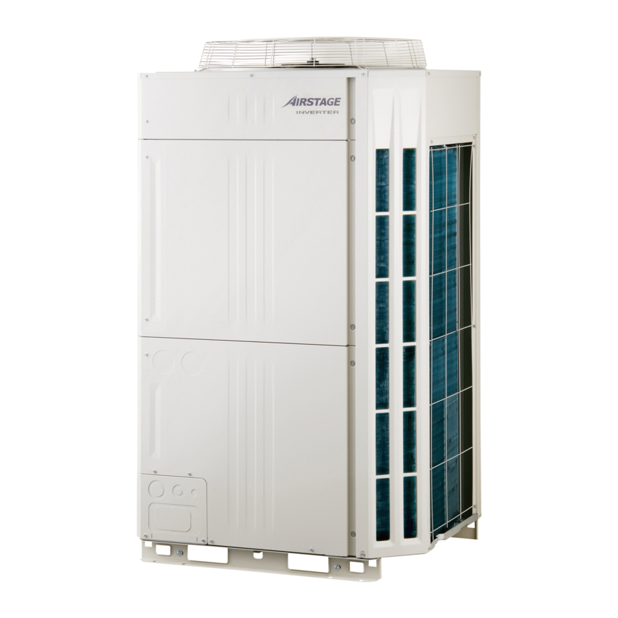
Multi Air Conditioning System for Buildings
Brand:
Fujitsu
| Category:
Air Conditioner
| Size: 75.59 MB
Table of Contents
Table of Contents
2
General Information
10
Features of System
11
High Efficiency Operation
11
High Design Freedom
13
High Reliability
15
Easy Installation
17
More Comfort & Convenience
19
Easy Service & Maintenance
21
Model Line up
23
Indoor Unit
24
Controller
27
Branch Kit
29
OTHERS (Optional Parts)
30
Model Selection Procedure
32
Outdoor Unit
38
Model Selection and Capacity Calculation
38
Method of Capacity Calculation
40
Capacity Table Cooling
44
Space Saving Combination
44
Energy Efficiency Combination
86
Space Saving Combination
110
Energy Efficiency Combination
152
Capacity Compensation Coefficient
176
Outdoor Unit
176
Operation Range
247
Electric Characteristics
252
Safety Devices
255
Locally Procured Parts
256
Snow Hood
259
Pressure Gauge
261
Central Drain Pan
264
Indoor Units
265
Features
266
Compact Duct Type
268
Low Static Pressure Duct Type
269
Duct Type
269
Specifications
275
Electric Characteristics
287
Group Remote Controller
536
Touch Panel Controller
536
Network Convertor
536
Signal Amplifier
540
Network Convertor for Lon Works
540
Outdoor Unit
542
INDOOR UNIT (Compact Cassette Type and Cassette Type)
555
INDOOR UNIT (Compact Wall Mounted Type)
556
Drain Connection
634
Outdoor Unit
634
Standard Accessories
645
Outdoor Unit
688
Installation Precautions
690
Optional Parts
694
Separation Tube
695
Header
700
Ev Kit
705
Adaptor / Convertor
707
Others
708
Advertisement
Fujitsu AIRSTAGE V-II Service Manual (231 pages)
multi air conditioning system for buildings
Brand:
Fujitsu
| Category:
Air Conditioner
| Size: 55.73 MB
Table of Contents
Table of Contents
3
1 Test Run
6
Test Run
8
Execution Procedure and Execution Precautions
8
Before Execution
8
Check Items before Power on
10
Test Run Method
10
Check Items after Power on
11
Test Run from Outdoor PC Board
13
Switch Position
13
Test Run Setting
13
Test Run from Remote Controller
14
Standard Wired Remote Controller
14
Standard Wireless Remote Controller
14
Touch Panel Controller
15
Test Run Operating Procedure
15
Test Run Control
17
Field Setting and Monitor Mode List
18
2 Outdoor Unit Operation Control
22
Outdoor Unit
24
Input / Output List
24
Compressor Operation
25
Operation / Stop Condition
25
Capacity Control
25
Speed Range of Start,Stop,And Operation
26
Target Low-Pressure and High-Pressure Control
26
Cooling Starting Process
26
Heating Starting Process
27
Compressor Sequence Operation
28
Fan Control
29
Cooling Operation
29
Heating Operation
30
Intermittent Fan Mode
30
Low Noise Mode
31
Expansion Valve Control
32
Snow Falling Protection Fan Mode
32
Other Control
32
Special Operation
33
Oil Recovery Operation
33
Cooling Oil Recovery Operation
33
Heating Oil Recovery Operation
33
Pre-Heat Operation
34
Defrost Operation Control
34
Protective Function List
36
3 Indoor Unit Operation
39
"AUTO" Position
41
Fan Speed Setting
41
Indoor Unit Operation
41
Fan Control
41
Operation Mode Control
42
Master Control
42
Auto Changeover
44
"COOL" Position
45
"HEAT" Position
45
Louver Control
46
Adjusting the Direction of Air Circulation
46
Large Ceiling Type
46
Universal Floor/Ceiling Type
46
Horizontal Air Direction Adjustment
47
Swing Operation
47
About Vertical Airflow SWING Operation
48
To Select Horizontal Airflow SWING Operation
48
To Stop Horizontal Airflow SWING Operation
48
About Horizontal Airflow Swing Operation
48
Electronic Expansion Valve Control
49
Drain Pump Operation
49
Initialization
49
Operation Control
49
Function
50
Auto Restart
50
Icing Protection Control
50
Oil Recovery Operation
50
Timer Control
51
Wireless Remote Controller
51
Program Timer
51
Sleep Timer
51
Group Remote Controller
53
Weekly Timer
53
Wired Remote Controller
55
On/Off Timer
55
Weekly Timer
56
Temperature Set Back Timer
58
4 Trouble Shooting
59
Troubleshooting
61
Normal Operation
61
Indoor Unit Display
61
Outdoor Unit Display
62
Abnormal Operation
63
Error Indication Flashing Pattern
63
Indoor Unit Display
63
ERROR Transition
64
LED Display
64
Operation Button
64
Outdoor Unit Display
64
Error Code List for Outdoor Unit
65
Remote Controller Display
66
Error Code List for Simple and Wired Remote Controller
67
Trouble Level of System
68
Error History Mode
70
Trouble Shooting with Error Code (INDOOR UNIT)
71
Communication Error
79
Check Communication PCB and Controller PCB
81
Check if any Outside Cause such as Voltage Drop or Noise
81
Check the Connection
81
Check the Power Supply
82
Initial Setting Error
82
Trouble Shooting with Error Code (OUTDOOR UNIT)
82
Communication Error between Outdoor Unit
83
Noise, Momentary Open, Voltage Drop
83
Outdoor Unit Network Communication 1 Error
84
Outdoor Unit Network Communication 2 Error
85
Outdoor Unit Reverse Phase, Missing Phase Wire Error
86
Outdoor Unit EEPROM Access Error
87
Inverter Communication Error
88
Outdoor Unit EEPROM Data Error
89
Inverter Error
90
Inverter PCB Momentary Power Failure Detection
91
Magnetic Relay Error
92
Rush Current Limiting Resistor Temp Rise Protection
93
Outdoor Unit Communication PCB Parallel Communication Error
94
Discharge Temp Sensor 1 Error
95
Discharge Temp Sensor 2 Error
96
Compressor Temp Sensor 1 Error
97
Compressor Temp Sensor 2 Error
98
Outdoor Unit Heat Ex. Liquid Temp. Sensor Error
99
Outdoor Temp Sensor Error
100
Suction Gas Temp Sensor Error
101
Heat Sink Temp Sensor Error
102
Sub-Cool Heat EX. Gas Inlet Temp Sensor Error
103
Sub-Cool Heat EX. Gas Outlet Temp Sensor Error
104
Liquid Pipe Temp. Sensor 1 Error
105
Liquid Pipe Temp Sensor 2 Error
106
Current Sensor 1 Error
107
Discharge Pressure Sensor Error
108
Suction Pressure Sensor Error
109
High Pressure Switch 1 Error
110
High Pressure Switch 2 Error
111
Compressor 2 Error
112
Compressor 2 Current Value Error
113
Inverter Compressor Start up Error
114
Trip Detection
115
Compressor Motor Loss of Synchronization
116
Outdoor Unit Fan Motor Lock Error
117
Outdoor Unit Fan Motor Undervoltage
118
Outdoor Unit Fan Motor Temperature Abnormal
119
Slave Unit Error
120
Discharge Tempreture 1 Abnormal
121
Discharge Tempreture 2 Abnormal
122
Compressor 1 Tempreture Abnormal
123
Compressor 2 Tempreture Abnormal
124
High Pressure Abnormal
125
High Pressure Protection 1
126
High Pressure Protection 2
127
Low Pressure Abnormal
128
Heat Sink Temperature Abnormal
129
Auto Address Setting Error
130
Signal Amplifier Auto Address Error
130
Indoor Unit Number Shortage Error
131
Indoor Unit - no Power
132
Trouble Shooting with no Error Code
132
Outdoor Unit - no Power
133
No Operation (Power Is ON)
134
No Cooling
135
Abnormal Noise
136
Water Leaking
136
External Switch Controller (UTY-TEKX)
137
The Abnormality in Connection of Remote Controller Cable
137
Trouble Shooting for Optional Parts
137
Switch Operation Error
138
Transmission Error
138
Communication Error
139
Power Supply Error
139
Address Setting Error
140
Parallel Communication
140
Communication Error a
141
Communication Error B
141
PCB Error 1
142
Communication Error with Group Remote Controller
143
Refrigerant Circuit Address Setting Error
144
Software Error
144
Communication Error with Standard Remote Controller
146
Communication Error with Indoor Unit
147
Indoor / Outdoor Unit Error
149
PCB Error
150
Connection Error
151
System Error
152
Thermo Sensor Error
153
Indoor Unit - Remote Controller Communication Error
154
Incompatible Indoor Unit Is Connected
155
Unit Not Detected
156
Service Information
157
Backup Operation
157
Work Procedure after the Backup Operation
159
Service Parts Information
160
Diagnosis Method of Compressor (if Outdoor Unit 7 Segment LED Displays Error, Refer to Trouble Shooting )
160
Check Connection
161
Check Winding Resistance
161
Check Cause of Protector Operation
161
Inverter Compressor
162
IPM (Mounted on Inverter PCB)
165
3-Phase Diode Bridge
167
Appearance Check
167
Electric Check
167
Reactor (INV)
168
Reactor (DC Fan)
168
Resistor, Cement
169
Terminal
170
Magnetic Relay
170
Indoor Unit Electronic Expansion Valve
171
Outdoor Unit Electronic Expansion Valve
173
Outdoor Unit Solenoid Valve
175
Protection Function
175
4-WAY Valve
176
Indoor Unit Fan Motor
177
Discharge Pressure Sensor
184
Suction Pressure Sensor
184
Pressure Switch 1,2
185
Thermistor
186
5 Appending Data
187
Refrigerant Circuit
189
Symbol Description
192
Wiring Diagram
193
Indoor Unit
193
Outdoor Unit
209
Characteristics of Sensors
212
Pressure Senser
212
Thermistor Resistance
213
Saturation Temperature and Saturation Pressure Tables (R410A)
214
Temperature and Pressure of Refrigerant (Graph)
215
6 Disassembly Process
216
Disassembly Process
218
Appearance
218
Panel Top Removal
218
Control Box Cover Removal
218
Layout Plan in Control Box
219
Main PCB Removal
220
Inverter PCB Removal
221
Panel BTM Removal
222
Conduit Plate Removal
222
Control Box Open
223
Thermistors Removal
224
Solenoid Coils Removal
224
EEV Coils Removal
224
Pressure Sensors Removal
224
Fan Motor Removal
225
Comp Box Cover Removal
225
Compressor Removal
226
Precautions for Exchange of Refrigerant-Cycle-Parts
229
Fujitsu AIRSTAGE V-II Warranty Statement (2 pages)
Brand:
Fujitsu
| Category:
Air Conditioner
| Size: 0.05 MB
Advertisement
Advertisement
Related Products
Fujitsu Airstage V series
Fujitsu Airstage VR-II Series
Fujitsu Airstage J-II Series
Fujitsu Airstage UTY-LNHU
Fujitsu Airstage UTY-VBGX
Fujitsu Airstage UTY-TEKX
Fujitsu Airstage UTG-LCGVCB
Fujitsu Airstage Wall Series
Fujitsu AIRSTAGE UTB P Series
Fujitsu AirStage AG E014GCEH Series
Fujitsu Categories
Air Conditioner
Laptop
Server
Scanner
Storage
More Fujitsu Manuals
Login
Sign In
OR
Sign in with Facebook
Sign in with Google
Upload manual
Upload from disk
Upload from URL