Sign In
Upload
Manuals
Brands
ETAS Manuals
Computer Hardware
FETK-T1.1
ETAS FETK-T1.1 Manuals
Manuals and User Guides for ETAS FETK-T1.1. We have
3
ETAS FETK-T1.1 manuals available for free PDF download: User Manual
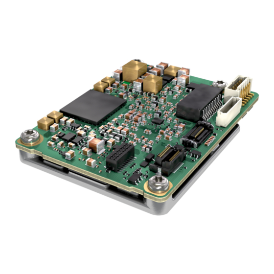
ETAS FETK-T1.1 User Manual (82 pages)
Emulator Probe for Infineon AURIX MCU Family
Brand:
ETAS
| Category:
Computer Hardware
| Size: 4 MB
Table of Contents
Table of Contents
3
About this Document
7
Classification of Safety Messages
7
Presentation of Instructions
7
Typographical Conventions
8
Presentation of Supporting Information
8
Basic Safety Notices
9
General Safety Information
9
Requirements for Users and Duties for Operators
9
Intended Use
9
Identifications on the Product
13
Taking the Product Back and Recycling
14
Declaration of Conformity
14
CE Declaration of Conformity (European Union)
14
UKCA Declaration of Conformity (Great Britain)
14
Rohs Conformity
14
European Union
14
People's Republic of China
15
Declarable Substances
15
Use of Open Source Software
15
Introduction
16
Product Variants
16
Applications
16
Features
17
General
17
Measurement
17
Calibration
17
Further Characteristics
18
Hardware Description
19
Architecture
19
Fig. 4-1 FETK-T1.1 Architecture
19
ECU Interface
20
Fig. 4-2 Location of the ECU Interfaces DAP (CON1) and Trace (CON2)
20
FETK Ethernet Interface
21
Fig. 4-3 Location of the Ethernet Interface Connector (CON3)
21
Power Supply
22
ECU Voltage Supervisor
22
Fig. 4-4 Location of the Power Supply Connector (CON4)
22
Status Leds
23
Data Access
24
Calibration Data Access
24
Measurement Data Access
25
DAP Interface
26
Trace Interface
26
Fig. 4-6 Equivalent Circuitry of the ECU DAP Interface (ECU)
26
Trigger Modes
27
Overview
27
Triggering Via Trace Interface
27
Pinless Triggering
27
Timer Triggering
28
Reset
28
Pull Calwakeup until Startup Handshake
29
Installation
30
Mounting the FETK-T1.1 into the ECU Housing
30
Thermal Connection Requirements
30
Mounting Material
31
Mounting Steps
31
Fig. 5-1 Heatspreader Screws
31
Fig. 5-2 Attaching the FETK-T1.1 to the ECU
32
Fig. 5-3 Thread Locking Fluid
33
Connection to the ECU
34
Fig. 5-4 FETK-T1.1 Connection to the ECU
34
Fig. 5-5 FETK-T1.1 Connection to the ECU
35
Wiring
36
FETK Ethernet Interface
36
Fig. 5-6 Wiring - FETK-T1.1 Ethernet Interface
36
Power Supply
37
Fig. 5-7 FETK-T1.1 Power Supply Wiring with CBAM300.3 Cable
37
Fig. 5-8 FETK-T1.1 Power Supply Wiring with CBAM320.1 Cable
37
Fig. 5-9 FETK-T1.1 Power Supply Wiring with CBAM350.1 Cable
38
Fig. 5-10 FETK-T1.1 Power Supply Wiring with CBAM305.1 Cable
38
Fig. 5-11 Isolated Power Supply Inside ECU
38
ETK / XETK / FETK Configuration
39
Overview
39
Configuration Parameter
40
Technical Data
41
System Requirements
41
ETAS Compatible Hardware
41
PC with One Ethernet Interface
41
Software Support
42
Data Emulation and Measurement Memory
42
Data Emulation Memory and Microcontroller Support
42
Measurement Data Memory
43
Trace Memory
43
Environmental Conditions
43
FETK Ethernet Interface
44
Fig. 7-1 Max. Thermal Resistance from FETK-T1.1 Heatspreader-Surface to Ambiente
44
Power Supply
45
Microcontroller Interface
46
Test Characteristics
46
DAP Timing Characteristics
47
2-Pin DAP Mode
47
3-Pin DAP Mode
48
Aurora Trace Timing Parameter
48
Electrical Characteristics
49
ECU Interface Connector DAP
49
ECU Interface Connector Aurora Trace
50
Pin Assignment
51
ECU Interface Connector CON1 (DAP Mode)
51
Fig. 7-2 Location of the FETK-T1.1 Interfaces
51
Fig. 7-3 ECU Interface Connector CON1
51
ECU Interface Connector CON2 (Aurora Trace)
53
Fig. 7-4 ECU Interface Connector CON2
53
Ethernet Interface Connector CON3
54
Power Supply Connector CON4
54
Fig. 7-5 Ethernet Interface Connector CON3
54
Fig. 7-6 Power Supply Connector CON4
54
Mechanical Dimensions
55
Top View
55
Fig. 7-7 FETK-T1.1 Dimensions - Top View
55
Side View
56
Fig. 7-8 FETK-T1.1 Dimensions - Side View
56
Cables and Accessories
57
Overview and Classification
57
Requirements for Failsafe Operation
57
CBAM300 Cable
58
Usage
58
Connectors
58
Temperature Range
58
Tightness
58
Ordering
58
Fig. 8-1 CBAM300.3 Cable - Dimensions
58
Fig. 8-2 CBAM300.3 Cable - Connectors
58
CBAM320 Cable
59
Usage
59
Connectors
59
Temperature Range
59
Tightness
59
Ordering
59
Fig. 8-3 CBAM320 Cable - Dimensions
59
Fig. 8-4 CBAM320 Cable - Connectors
59
CBAM340 Cable
60
Usage
60
Connectors
60
Temperature Range
60
Ordering
60
Fig. 8-5 CBAM340 Cable - Dimensions
60
Fig. 8-6 CBAM340 Cable - Connectors
60
CBAM350 Cable
61
Usage
61
Panel Cut-Out
61
Assembling
61
Fig. 8-7 CBAM350 Cable - Dimensions
61
Fig. 8-8 Dimension Panel Cut-Out
61
Temperature Range
62
Ordering
62
CBAM305 Cable
63
Usage
63
Dimensions
63
Fig. 8-9 CBAM305.1-0M6 Cable - Dimensions
63
Connectors
64
Fig. 8-10 CBAM305.1-2M2 Cable - Dimensions
64
Fig. 8-11 CBAM305.1-0M6 - Connectors
64
Fig. 8-12 CBAM305.1-2M2 - Connectors
64
Temperature Range
65
Tightness
65
Ordering
65
CBE260 Cable
66
Usage
66
Dimensions
66
Connectors
66
Temperature Range
66
Ordering
66
Fig. 8-14 CBE260 - Connectors
66
ETAM4 Adapter
67
Usage
67
Pin Numbering
67
Ordering
67
Fig. 8-15 ECU Adapter ETAM4 (Bottom View)
67
Fig. 8-16 ECU Adapter ETAM4 (Side View)
67
Fig. 8-17 ECU Adapter ETAM4 (Mated High)
67
Fig. 8-18 ECU Adapter ETAM4 (Pin Numbering)
67
ETAM8 Adapter
68
Usage
68
Pin Numbering
68
Fig. 8-19 ECU Adapter ETAM8 (Bottom View)
68
Fig. 8-20 ECU Adapter ETAM8 (Side View)
68
Fig. 8-21 ECU Adapter ETAM8 (Pin Numbering)
68
ECU Connector: Signal Modes
69
Temperature Range
69
Ordering
69
ETV5 Cable
70
Usage
70
Pin Assignment
70
Temperature Range
70
Ordering
70
Fig. 8-22 Power Supply Cable ETV5
70
ETAM2 Adapter
71
Pin Assignment
71
ECU Signals
71
Ordering
71
Fig. 8-23 FETK - ECU Adapter ETAM2
71
Fig. 8-24 ETAM2 Connector
71
ETAM5 Adapter
72
Pin Assignment
72
Ordering
72
Fig. 8-25 FETK - ECU Adapter ETAM5
72
ETAM9 Adapter
73
Usage
73
ECU Signals
73
Temperature Range
73
Order Information
73
Fig. 8-26 FETK/ XETK - ECU Adapter ETAM9
73
ETAM10 Adapter
74
Usage
74
Dimensions
74
Fig. 8-27 FETK/ XETK - ECU Adapter ETAM10
74
Fig. 8-28 ETAM10 Adapter Dimensions
74
ECU Signals
75
Temperature Range
75
Order Information
75
Ordering Information
76
Fetk-T1.1A
76
Fetk-T1.1B
76
Cable
76
ECU Adapter Cable
77
ECU Adapter and Power Supply Cable
77
Gbit Ethernet and Power Supply Cable
78
ECU Adapter
78
Power Supply Cable
78
Power Supply
78
Contact Information
79
Figures
80
Index
82
Advertisement
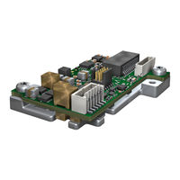
ETAS FETK-T1.1 User Manual (72 pages)
Emulator Probe for Infineon AURIX MCU Family
Brand:
ETAS
| Category:
Recording Equipment
| Size: 2 MB
Table of Contents
Table of Contents
3
1 About this Document
7
Classification of Safety Messages
7
Presentation of Instructions
7
Typographical Conventions
8
Presentation of Supporting Information
8
2 Basic Safety Notices
9
General Safety Information
9
Requirements for Users and Duties for Operators
9
Intended Use
9
Identifications on the Product
13
Fig. 2-1 Adhesive Label (Example: Label for XETK-S14.0)
13
Taking the Product Back and Recycling
14
CE Marking
14
Rohs Conformity
14
European Union
14
China
14
WEEE-Symbol
14
Declarable Substances
15
Use of Open Source Software
15
3 Introduction
16
Applications
16
Fetk-S1.1
16
Features
17
4 Hardware Description
19
Architecture
19
Fig. 4-1 FETK-S1.1 Architecture
19
ECU Interface
20
Fig. 4-2 Location of the ECU Interfaces
20
Fig. 4-3 ETAM8 Adapter Mounted at CON1
20
FETK Ethernet Interface
21
Fig. 4-4 Location of the FETK Ethernet Interface Connector (CON3)
21
DAP Interface
22
Fig. 4-5 Equivalent Circuitry of the ECU DAP Interface (ECU)
22
Power Supply
23
ECU Voltage Supervisor
23
Fig. 4-6 Location of the FETK-S1.1 Power Supply Connectors
23
Data Emulation and Data Measurement
24
Trace Based Measurement
25
Trigger Modes: Overview
25
Pinless Triggering
26
Startup Handshake
26
FETK Trigger Generation
26
Timer Triggering
27
Trace Triggering
27
Reset
27
Pull Calwakeup until Startup Handshake
28
5 Installation
29
Connection to the ECU
29
Fig. 5-1 FETK-S1.1 Connection to the ECU
29
Thermal Connection
30
Fig. 5-2 FETK-S1.1 Connection to the ECU
30
Wiring
31
FETK Ethernet Interface
31
Power Supply
31
Fig. 5-3 Wiring - FETK Ethernet Interface
31
Fig. 5-4 FETK-S1.1 Power Supply Wiring with CBAM300.3 Cable
31
Fig. 5-5 FETK-S1.1 Power Supply Wiring with CBAM320.1 Cable
32
Fig. 5-6 FETK-S1.1 Power Supply Wiring with CBAM350.1 Cable
32
Fig. 5-7 FETK-S1.1 Power Supply Wiring with CBAM305.1 Cable
33
Fig. 5-8 Isolated Power Supply Inside ECU
33
6 ETK / XETK / FETK Configuration
34
Overview
34
Configuration Parameter
35
7 Technical Data
36
System Requirements
36
ETAS Compatible Hardware
36
PC with One Ethernet Interface
36
Software Support
36
Data Emulation and Measurement Memory
38
Data Emulation Memory and Microcontroller Support
38
Measurement Data Memory
38
FETK Ethernet Interface
38
Environmental Conditions
39
Power Supply
39
Microcontroller Interface
40
Test Characteristics
40
DAP Timing Characteristics
40
2-Pin DAP Mode
41
Fig. 7-1 2-Pin DAP Mode Timing
41
Fig. 7-2 3-Pin DAP Mode Timing
41
Electrical Characteristics
42
ECU Interface Connector
42
Pin Assignment
44
ECU Interface Connector CON1 (JTAG Mode)
44
Fig. 7-3 Location of the FETK-S1.1 Interfaces
44
Power Supply Connector CON2
45
Mechanical Dimensions
46
Top View
46
Fig. 7-4 FETK-S1.1 Dimensions - Top View
46
Side View
47
Fig. 7-5 FETK-S1.1 Dimensions - Side View
47
8 Cables and Accessories
48
Overview and Classification
48
Requirements for Failsafe Operation
48
CBAM300 Cable
49
Usage
49
Connectors
49
Temperature Range
49
Tightness
49
Ordering
49
Fig. 8-1 CBAM300.3 Cable - Dimensions
49
Fig. 8-2 CBAM300.3 Cable - Connectors
49
CBAM320 Cable
50
Usage
50
Connectors
50
Temperature Range
50
Tightness
50
Ordering
50
Fig. 8-3 CBAM320 Cable - Dimensions
50
Fig. 8-4 CBAM320 Cable - Connectors
50
CBAM340 Cable
51
Usage
51
Connectors
51
Temperature Range
51
Ordering
51
Fig. 8-5 CBAM340 Cable - Dimensions
51
Fig. 8-6 CBAM340 Cable - Connectors
51
CBAM350 Cable
52
Usage
52
Panel Cut-Out
52
Assembling
52
Fig. 8-7 CBAM350 Cable - Dimensions
52
Fig. 8-8 Dimension Panel Cut-Out
52
Temperature Range
53
Ordering
53
CBAM305 Cable
54
Usage
54
Dimensions
54
Fig. 8-9 CBAM305.1-0M6 Cable - Dimensions
54
Connectors
55
Fig. 8-10 CBAM305.1-2M2 Cable - Dimensions
55
Fig. 8-11 CBAM305.1-0M6 - Connectors
55
Fig. 8-12 CBAM305.1-2M2 - Connectors
55
Temperature Range
56
Tightness
56
Ordering
56
CBE260 Cable
57
Usage
57
Dimensions
57
Connectors
57
Temperature Range
57
Ordering
57
Fig. 8-14 CBE260 - Connectors
57
ETAM8 Adapter
58
Usage
58
Pin Numbering
58
Fig. 8-15 ECU Adapter ETAM8 (Bottom View)
58
Fig. 8-16 ECU Adapter ETAM8 (Side View)
58
Fig. 8-17 ECU Adapter ETAM8 (Pin Numbering)
58
ECU Connector: Signal Modes
59
Temperature Range
59
Ordering
59
ETV5 Cable
60
Usage
60
Pin Assignment
60
Temperature Range
60
Ordering
60
Fig. 8-18 Power Supply Cable ETV5
60
ETAM2 Adapter
61
Pin Assignment
61
ECU Signals
61
Ordering
61
Fig. 8-19 FETK - ECU Adapter ETAM2
61
Fig. 8-20 ETAM2 Connector
61
ETAM5 Adapter
62
Pin Assignment
62
Ordering
62
Fig. 8-21 FETK - ECU Adapter ETAM5
62
ETAM9 Adapter
63
Usage
63
ECU Signals
63
Temperature Range
63
Order Information
63
Fig. 8-22 FETK/ XETK - ECU Adapter ETAM9
63
ETAM10 Adapter
64
Usage
64
Dimensions
64
Fig. 8-23 FETK/ XETK - ECU Adapter ETAM10
64
Fig. 8-24 ETAM10 Adapter Dimensions
64
ECU Signals
65
Temperature Range
65
Order Information
65
9 Ordering Information
66
Fetk-S1.1
66
Cable
66
ECU Adapter Cable
67
ECU Adapter and Power Supply Cable
67
Gbit Ethernet and Power Supply Cable
68
ECU Adapter
68
Power Supply Cable
68
Power Supply
68
10 Contact Information
69
Figures
70
Index
72
ETAS FETK-T1.1 User Manual (76 pages)
Emulator Probe for Infineon AURIX MCU Family
Brand:
ETAS
| Category:
Test Equipment
| Size: 2 MB
Table of Contents
Fetk-T1.1
2
Table of Contents
3
Safety Information
7
Intended Use
8
Classification of Safety Messages
8
Safety Information
9
Assembly
9
Operation
9
Electrical Connection
9
Cables and Accessories
10
Transport
10
Maintenance
11
Identifications on the Product
11
Taking the Product Back and Recycling
12
Declaration of Conformity
12
CE Declaration of Conformity (European Union)
12
UKCA Declaration of Conformity (Great Britain)
12
Rohs Conformity
12
European Union
12
Fig. 1-1 WEEE-Symbol
12
People's Republic of China
13
Declarable Substances
13
Use of Open Source Software
13
Introduction
14
Product Variants
14
Applications
14
Features
15
General
15
Measurement
15
Calibration
15
Further Characteristics
16
Hardware Description
17
Architecture
17
Fig. 3-1 FETK-T1.1 Architecture
17
ECU Interface
18
Fig. 3-2 Location of the ECU Interfaces DAP (CON1) and Trace (CON2)
18
FETK Ethernet Interface
19
Power Supply
19
Fig. 3-3 Location of the Ethernet Interface Connector (CON3)
19
ECU Voltage Supervisor
20
Fig. 3-4 Location of the Power Supply Connector (CON4)
20
Status Leds
21
Data Access
22
Calibration Data Access
22
Measurement Data Access
23
DAP Interface
23
Fig. 3-6 Equivalent Circuitry of the ECU DAP Interface (ECU)
23
Trace Interface
24
Trigger Modes
24
Overview
24
Triggering Via Trace Interface
24
Pinless Triggering
25
Timer Triggering
25
Reset
26
Pull Calwakeup until Startup Handshake
26
Installation
27
Mounting the FETK-T1.1 into the ECU Housing
27
Thermal Connection Requirements
27
Mounting Material
27
Mounting Steps
28
Fig. 4-1 Heatspreader Screws
28
Connection to the ECU
30
Wiring
32
FETK Ethernet Interface
32
Power Supply
32
Fig. 4-6 Wiring - FETK-T1.1 Ethernet Interface
32
Fig. 4-7 FETK-T1.1 Power Supply Wiring with CBAM300.3 Cable
33
Fig. 4-8 FETK-T1.1 Power Supply Wiring with CBAM320.1 Cable
33
Fig. 4-9 FETK-T1.1 Power Supply Wiring with CBAM350.1 Cable
34
Fig. 4-10 FETK-T1.1 Power Supply Wiring with CBAM305.1 Cable
34
Fig. 4-11 Isolated Power Supply Inside ECU
35
ETK / XETK / FETK Configuration
36
Overview
36
Configuration Parameter
36
Technical Data
38
System Requirements
38
ETAS Compatible Hardware
38
PC with One Ethernet Interface
38
Software Support
39
Data Emulation and Measurement Memory
39
Data Emulation Memory and Microcontroller Support
39
Measurement Data Memory
40
Trace Memory
40
Environmental Conditions
40
FETK Ethernet Interface
41
Fig. 6-1 Max. Thermal Resistance from FETK-T1.1 Heatspreader-Surface to Ambiente
41
Power Supply
42
Microcontroller Interface
43
Test Characteristics
43
DAP Timing Characteristics
44
2-Pin DAP Mode
44
3-Pin DAP Mode
45
Aurora Trace Timing Parameter
45
Electrical Characteristics
46
ECU Interface Connector DAP
46
ECU Interface Connector Aurora Trace
47
Pin Assignment
48
ECU Interface Connector CON1 (DAP Mode)
48
Fig. 6-2 Location of the FETK-T1.1 Interfaces
48
ECU Interface Connector CON2 (Aurora Trace)
49
Ethernet Interface Connector CON3
50
Power Supply Connector CON4
50
Fig. 6-5 Ethernet Interface Connector CON3
50
Fig. 6-6 Power Supply Connector CON4
50
Mechanical Dimensions
51
Top View
51
Fig
51
Side View
52
Cables and Accessories
53
Overview and Classification
53
Requirements for Failsafe Operation
53
CBAM300 Cable
54
Usage
54
Connectors
54
Temperature Range
54
Tightness
54
Ordering
54
Fig. 7-1 CBAM300.3 Cable - Dimensions
54
CBAM320 Cable
55
Usage
55
Connectors
55
Temperature Range
55
Tightness
55
Ordering
55
CBAM340 Cable
56
Usage
56
Connectors
56
Temperature Range
56
Ordering
56
CBAM350 Cable
57
Usage
57
Panel Cut-Out
57
Assembling
57
Fig. 7-7 CBAM350 Cable - Dimensions
57
Temperature Range
58
Ordering
58
CBAM305 Cable
58
Usage
58
Dimensions
58
Fig. 7-9 CBAM305.1-0M6 Cable - Dimensions
58
Connectors
59
Fig. 7-10 CBAM305.1-2M2 Cable - Dimensions
59
Fig. 7-11 CBAM305.1-0M6 - Connectors
59
Fig. 7-12 CBAM305.1-2M2 - Connectors
59
Temperature Range
60
Tightness
60
Ordering
60
CBE260 Cable
60
Usage
60
Dimensions
60
Connectors
60
Fig. 7-14 CBE260 - Connectors
60
Temperature Range
61
Ordering
61
ETAM4 Adapter
61
Usage
61
Pin Numbering
61
Fig. 7-15 ECU Adapter ETAM4 (Bottom View)
61
Fig. 7-17 ECU Adapter ETAM4 (Mated High)
61
Fig. 7-18 ECU Adapter ETAM4 (Pin Numbering)
61
Ordering
62
ETAM8 Adapter
62
Usage
62
Pin Numbering
62
Fig. 7-19 ECU Adapter ETAM8 (Bottom View)
62
Fig. 7-21 ECU Adapter ETAM8 (Pin Numbering)
62
ECU Connector: Signal Modes
63
Temperature Range
63
Ordering
63
ETV5 Cable
63
Advertisement
Advertisement
Related Products
ETAS FETK-S2.1
ETAS FETK-T4.0B
ETAS FETK-T3.0
ETAS FETK-S1.1
ETAS FETK-T5.0A
ETAS F-00K-102-632
ETAS F-00K-110-731
ETAS F-00K-110-531
ETAS F-00K-110-901
ETAS F 00K 115 627
ETAS Categories
Control Unit
Computer Hardware
Measuring Instruments
Recording Equipment
I/O Systems
More ETAS Manuals
Login
Sign In
OR
Sign in with Facebook
Sign in with Google
Upload manual
Upload from disk
Upload from URL