Sign In
Upload
Manuals
Brands
ETAS Manuals
Control Unit
ES910.3-A
ETAS ES910.3-A Manuals
Manuals and User Guides for ETAS ES910.3-A. We have
2
ETAS ES910.3-A manuals available for free PDF download: User Manual
ETAS ES910.3-A User Manual (116 pages)
Prototyping and Interface Module
Brand:
ETAS
| Category:
Control Unit
| Size: 2 MB
Table of Contents
Table of Contents
3
1 About this Manual
8
Identification of Safety Notices
8
Presentation of Information
8
Scope of Supply
9
Additional Information
9
2 Basic Safety Notices
10
General Safety Information
10
Requirements for Users and Duties for Operators
10
Intended Use
10
3 Hardware Description
16
Overview
16
ES910.3-A Features
16
Rapid Prototyping of Software Functions
16
Housing
18
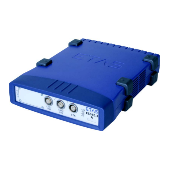
Fig. 3-1 ES910.3-A View of the Device
18
Interfaces
19
Front Panel
19
Fig. 3-2 ES910.3-A Front Panel
19
Back Panel
20
Fig. 3-3 ES910.3-A Back Panel
20
Indicators
21
ES910.3-A Operational State
21
Flash Codes
21
Fig. 3-4 Flash Codes of the Indicators
21
ES910.3-A Functional State
22
Functional State of Individual Interfaces
23
Acoustic Signal
24
4 Functional Description
25
Block Diagram
25
Power Supply (7-29V DC)
25
ON/AUTO Switch
25
ON/AUTO Switch in Position „ON
25
Fig. 4-1 Block Diagram of the ES910.3-A
25
ON/AUTO Switch in Position „AUTO
26
Operational States
26
Operational State: "Off
26
Operational State: "On
26
Operational State: "Standby
26
Wake-Up" Function
26
Fig. 4-2 "Wake-Up" Function
26
Fig. 4-3 Operational States of the Power Supply (Simplified)
27
Service Interface (SP)
28
Manual Trigger" Function
28
Fig. 4-4 "Manual Trigger" Function with Button between Pin 1 and Pin 2
28
Wake up Control" Pin
29
Fig. 4-5 "Manual Trigger" Function with Terminal 15
29
Fig. 4-6 Connecting the Wake up Pin to Terminal 15
29
PC Interface (PC)
30
ES910.3-A Standalone Operation
30
Mixed Network
30
CAN Interface (CAN1/LIN1, CAN2/LIN2)
30
Operating Modes
30
Bus Terminating Resistor
31
Feature
31
LIN Interface (CAN1/LIN1, CAN2/LIN2)
31
Feature
32
Operating Modes
32
Power Supply on the Bus
32
ETK Interface (ETK)
32
Fig. 4-7 Power Supply at the LIN Bus
32
Initialization
33
Operating Modes
33
IO Interface (IO)
34
Daisy Chain" Operating Mode
34
Operating Modes
34
Ethercat" Operating Mode
35
Feature
35
Overload for Rapid Prototyping Applications
36
ECU Interface (ECU)
37
Connecting the Hardware and Configuration
37
Hardware Detection and Protocols
38
XETK / ECU with Ethernet Interface" Operating Mode
38
Fig. 4-8 Operation with External Switch and Ilinkrt TM at the ECU Interface
38
Ethernet Interface with Ilinkrt TM Protocol" Operating Mode
39
External Switch with ETAS Modules" Operating Mode
40
Feature
40
Extension Slot
40
Nvram
40
Watchdog
40
Real Time Clock
41
Firmware
41
Firmware of the ES910.3-A
41
Firmware of the Modules Mountable in the Extension Slot
41
5 Getting Started
42
Transferring Dissipated Heat
42
Monitoring the Temperature
42
Ventilation of the Module
42
Setup
42
Requirements for Setting up an ES910.3-A Module
42
Requirements When Setting up with Other Modules
43
Fig. 5-1 Free Space Around the ES910.3-A
43
Assembly and Locking
44
Fixing a Module Onto a Carrier System
44
Fig. 5-2 Levering off the Plastic Foot
44
Connecting Several Modules Mechanically
45
Fig. 5-3 Tapped Blind Hole
45
Fig. 5-4 Connecting the ES910.3-A to Another Module
46
Applications
47
ETK Bypass Systems
47
Fig. 5-5 ETK Bypass System with ES910.3-A
47
Fig. 5-6 ETK Bypass System with ES910.3-A
48
Fig. 5-7 ETK Bypass System with ES910.3-A
49
ETK Bypass System with Simultaneous Measuring and Calibration
50
Fig. 5-8 ETK Bypass System with Simultaneous Measuring and Calibration
50
Fig. 5-9 ETK Bypass System with Daisy Chain Modules
51
ES910.3-A with ES720.1 Drive Recorder
53
Fig. 5-10 ETK Bypass System with ES720 Drive Recorder and Daisy Chain Modules
53
ES910.3-A for Fast Application Access with INCA-MCE
55
Fig. 5-11 Test Bench System with ECU Access in Real-Time
55
Cabling
57
PC Interface (PC)
57
Power Supply Interface (7-29V DC)
57
IO Interface (IO)
58
ECU Interface (ECU)
59
Configuring the ES910.3-A
60
Configuring the "Wake Up" Function
60
Launching the ES910.3-A Web Interface
60
Web Interface
60
Configuring the CAN/LIN Interfaces
61
Configuring the IO Interface
62
Configuring the ECU Interface
63
6 Troubleshooting Problems
65
Troubleshooting ES910.3-A Problems
65
Problems and Solutions
67
Network Adapter Cannot be Selected Via Network Manager
67
Search for Ethernet Hardware Fails
68
Personal Firewall Blocks Communication
69
7 Technical Data
74
General Data
74
Identifications on the Product
74
Cleaning the Product
75
Environmental Conditions
75
Fulfilled Standards and Norms
75
Maintenance of the Product
75
Mechanical Data
76
Rohs Conformity
76
China
76
European Union
76
CE Marking
76
Product Return and Rrcycling
76
Fig. 7-1 WEEE Symbol
76
Use of Open Source Software
77
System Requirements
77
Hardware
77
Supported Applications and Software Requirements
78
Compatibility between Rapid Prototyping Models and ES910.3-A Firm
80
Information about the Combination ES910.3-A with ES715 Drive
80
Recorder
80
Ware
80
Electrical Data
81
PC Interface (PC)
81
Power Supply
81
Simulation Controller
81
CAN Interfaces (CAN1/LIN1 and CAN2/LIN2)
82
LIN Interfaces (CAN1/LIN1 and CAN2/LIN2)
82
ETK Interface (ETK)
83
Service Interface (SP)
84
ECU Interface (ECU)
85
IO Interface
85
Miscellaneous
86
Pin Assignment
87
Power Supply Interface (7-29V DC)
87
Fig. 7-2 Power Supply Interface (7-29V DC)
87
PC Interface (PC)
88
Fig. 7-3 PC Interface (PC)
88
CAN/LIN Interface (CAN1/LIN1 and CAN2/LIN2)
89
Fig. 7-4 CAN/LIN Interface (CAN1/LIN1 and CAN2/LIN2)
89
ETK Interface (ETK)
90
Fig. 7-5 ETK Interface (ETK)
90
SP Interface (SP)
91
Fig. 7-6 SP Interface (SP)
91
IO Interface (IO)
92
Fig. 7-7 IO Interface (IO)
92
ECU Interface (ECU)
93
Fig. 7-8 ECU Interface (ECU)
93
Cables and Accessories
94
Power Supply Cable
94
CBP120 Cable
95
Fig. 8-1 CBP120-2 (Power Supply Cable with Standard Banana Plugs)
95
CBP1205 Cable
96
Fig. 8-2 CBP1205 (Power Supply Cable with Safety Banana Plugs)
96
PC Interface Cable
97
Ethernet Adapter Cable (1 Gbit/S / 100 Mbit/S)
97
Fig. 8-3 CBE200-X Cable
97
Fig. 8-4 CBAE330.2 Cable
97
Combined CAN and LIN Cable
98
Fig. 8-5 CBCFI100 Cable
98
CAN Interface Cable
100
K106 Cable
100
K107 Cable
100
Fig. 8-6 K106 Cable
100
Fig. 8-7 K107 Cable
100
CBAC130-3 Cable
101
CBAC140-3 Cable
101
CBCX130-2 Cable
101
Fig. 8-8 CBCX130-X Cable
101
Fig. 8-9 CBAC130-X Cable
101
Fig. 8-10 CBAC140-3 Cable
101
CBAC150-2M5 Cable
102
CAN Terminating Resistor
102
Fig. 8-11 CBAC150-2M5 Cable
102
Fig. 8-12 CBCX131-0 Terminating Resistor
102
ETK Interface Cable CBM150-X
103
ECU Interface Cable
103
Fig. 8-13 CBM150-X Cable
103
Fig. 8-14 CBE230.1 Cable
103
Ethernet Chain Connection and Power Supply Cable (Daisy Chain Modules)
104
CBEP430.1 Cable
104
CBEP4305.1 Cable
104
Fig. 8-15 Cable CBEP430.1
104
Fig. 8-16 Cable CBEP4305.1
104
9 Ordering Information
105
Es910.3-A
105
ES910.3-A with CBP120 Power Supply Cable
105
8 Cables and Accessories
106
ETK Interface Cable
107
SP Interface Cable
108
Housing Accessories
109
10 ETAS Contact Addresses
110
Figures
111
Index
113
Advertisement
ETAS ES910.3-A User Manual (43 pages)
CAN FD Module (2 Channels)
Brand:
ETAS
| Category:
I/O Systems
| Size: 30 MB
Table of Contents
Table of Contents
3
About this Document
5
Classification of Safety Messages
5
Presentation of Instructions
5
Typographical Conventions
6
Presentation of Supporting Information
6
About this Manual
7
Scope of Supply
7
Additional Information
7
Basic Safety Notices
8
General Safety Information
8
Requirements for Users and Duties for Operators
8
Intended Use
8
Hardware Description
14
Overview
14
Properties
14
ES922.1 Module
14
Module
15
Connections
15
Fig. 4-2 ES922.1 Connections
15
Functional Status Display
16
Functional Description
17
Block Diagram
17
CAN Interfaces
17
Operating Modes
17
Fig. 5-1 Block Diagrames922.1
17
Timestamp
18
Feature
18
Bus Terminating Resistor
18
Functions "Wake-Up"And "Sleep
19
Wake-Up" Function
19
Sleep" Function
19
Configuration
19
Firmware
20
Firmware for the ES910.3-A and ES922.1 Modules
20
Firmware Update
20
Commissioning
21
Assembly
21
Removing the Front Panel of the ES910.3-A Extension Slot
21
Installing the ES922.1 in the ES910.3-A Module
22
Removal
24
Removing the ES922.1 from the ES910.3-A Module
24
Fitting the Front Panel of the ES910.3-A Extension Slot
25
Configuring the ES922.1
25
Configuring in the Application Software
25
Configuring in the Web Interface
25
Cabling
27
Fig. 6-1 Cabling the ES922.1 and ES910.3-A Modules
27
Technical Data
29
General Data
29
Identifications on the Product
29
Satisfied Norms and Standards
30
Rohs Conformity
30
CE Conformity
30
UKCA Conformity
31
KCC Conformity
31
Product Return and Recycling
31
Materials Subject to Declaration
31
Marking for WEEE, See Chapter
31
WEEE Symbol
31
Use of Open Source Software
32
System Requirements
32
Hardware
32
Software
32
Firmware
33
Ambient Conditions
33
Mechanical Data
33
Terminal Assignment
34
Electrical Data
34
Voltage Supply
34
Fig. 7-2 CAN Interface (CAN1 and CAN2)
34
CAN Interface
35
Cables and Accessories
36
CAN Cables
36
Cable K106
36
Cable K107
36
Cable CBCX130
37
Cable CBAC140
37
Cable CBAC150
37
CAN Terminating Resistor
38
Fig. 8-6 Terminating Resistor CBCX131-0
38
Order Information
39
Accessories
39
Spare Screws
39
Contact Information
40
Figures
41
Index
42
Advertisement
Related Products
ETAS FlexRay ES920.1
ETAS ES585.1
ETAS ES511.1
ETAS ES413.1
ETAS ES413.1-L1B
ETAS ES313.1
ETAS ES581.4
ETAS ES4455.2
ETAS ES4452.1
ETAS ES4458.1
ETAS Categories
Control Unit
Computer Hardware
Measuring Instruments
Recording Equipment
I/O Systems
More ETAS Manuals
Login
Sign In
OR
Sign in with Facebook
Sign in with Google
Upload manual
Upload from disk
Upload from URL