Sign In
Upload
Manuals
Brands
Emerson Manuals
Transmitter
Rosemount 3144P
Emerson Rosemount 3144P Manuals
Manuals and User Guides for Emerson Rosemount 3144P. We have
10
Emerson Rosemount 3144P manuals available for free PDF download: Reference Manual, Quick Start Manual
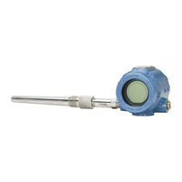
Emerson Rosemount 3144P Reference Manual (252 pages)
Temperature Transmitter
Brand:
Emerson
| Category:
Transmitter
| Size: 6.47 MB
Table of Contents
Table of Contents
5
1 Section 1: Introduction
11
Overview
11
Manual
11
Transmitter
12
Considerations
13
General
13
Electrical
13
Environmental
13
Moist or Corrosive Environments
14
Installation
15
Software Compatibility
15
Return of Materials
15
3144P Revisions
16
Confirm HART Revision Capability
18
2 Section 2: Installation
19
Safety Messages
19
Commissioning
20
Setting the Loop to Manual
20
Set the Switches
21
Mounting
23
Installation
25
Typical North American Installation
25
Typical European Installation
26
In Conjunction with a Rosemount 333 HART Tri-Loop
27
(HART / 4-20 Ma Only)
27
LCD Display
28
Multichannel Installation (HART / 4-20 Ma Only)
30
Wiring
30
HART / 4-20 Ma
30
Foundation Fieldbus
33
Sensor Connections
33
Power Supply
34
Surges/Transients
35
Grounding
35
Transmitter Housing
37
3 Section 3: HART Commissioning
39
Overview
39
Confirm HART Revision Capability
39
Safety Messages
40
Field Communicator
40
Updating the HART Communication Software
40
Device Dashboard Menu Tree
42
Device Dashboard Fast Key Sequences
48
Review Configuration Data
50
Review
50
Check Output
50
Analog Output
50
Configuration
50
Variable Mapping
51
Sensor Configuration
51
Change Type and Connections
51
Output Units
52
Sensor 1 Serial Number
52
Sensor 2 Serial Number
52
2-Wire RTD Offset
52
Terminal (Body) Temperature
53
Dual-Sensor Configuration
53
Device Output Configuration
101
PV Range Values
101
Process Variable Damping
102
Alarm and Saturation
103
HART Output
104
LCD Display Options
104
Device Information
104
Tag
104
Long Tag
104
Date
105
Descriptor
105
Message
105
Measurement Filtering
105
150/60 Hz Filter
105
2Master Reset
106
3Intermittent Sensor Detect
106
4Intermittent Threshold
106
5Open Sensor Holdoff
107
Diagnostics and Service
107
1Loop Test
108
Multidrop Communication
108
Use with the HART Tri-Loop
109
Calibration
131
1Calibration Frequency
131
Trim the Transmitter
132
1Sensor Input Trim
133
2Active Calibrator and EMF Compensation
134
3Transmitter-Sensor Matching
135
A Output Trim or Scaled Output Trim
142
5Output Trim
142
6Scaled Output Trim
143
Troubleshooting
143
1Overview
143
2LCD Display
147
3Spare Parts
148
4 Section 4: Foundation™ Fieldbus Configuration
149
Overview
149
Safety Messages
149
General Block Information
150
Device Description
150
Node Address
150
Modes
150
Link Active Scheduler
151
Capabilities
152
Foundation Fieldbus Function Blocks
152
Resource Block
154
Features and Features_Sel
154
Plantweb
155
Alerts
155
Plantweb ™ Alerts
155
Recommended Actions for Plantweb Alerts
158
Recommended Actions for Field Diagnostics Per NE107
159
Resource Block Diagnostics
159
Sensor Transducer Block
160
Sensor Transducer Block Diagnostics
161
LCD Display Transducer Block
162
Custom Meter Configuration
162
LCD Display Transducer Block Diagnostics
163
Hot Backup ™ Transducer
164
Analog Input (AI)
165
Simulation
165
Configure the AI Block
166
Filtering
169
Process Alarms
169
Status
170
Advanced Features
170
Analog Input Diagnostics
171
Operation
172
1Overview
172
2Trim the Transmitter
172
3Advanced Diagnostics
174
4Statistical Process Monitoring (SPM)
176
5SPM Configuration
177
Troubleshooting Guides
178
1Foundation Fieldbus
181
2LCD Display
182
5 Section 5: Maintenance
185
Safety Messages
185
Maintenance
186
Test Terminal (HART / 4-20 Ma Only)
186
Sensor Checkout
186
Electronics Housing
186
Transmitter Diagnostics Logging
187
6 Section 6: Certified Safety Instrumented System (Safety-
189
Safety Instrumented Systems (SIS) Certification
189
Rosemount ® 3144P Safety Certified Identification
189
Rosemount® 3144P Safety Certified Identification
189
Installation
190
Commissioning
190
Configuration
190
Safety Messages
190
Certified Safety Instrumented System (Safety-Certified)
190
Certification
191
3144P Safety-Certified Identification
191
Installation
191
Commissioning
191
Configuration
191
Operation and Maintenance
192
1Proof Test
192
2Inspection
194
Specifications
194
1Failure Rate Data
194
2Product Life
194
Spare Parts
194
7 Section 7: Prior Use (PU) Safety Instrumented System
195
Overview
195
Note
195
This Section Applies to 4-20 Ma Only
195
Safe Failure Fraction
196
Installation
196
Switches
196
Changing Switch Position
196
Proof Test
198
Functional Specifications
199
Physical Specifications
199
A.1.1 Functional Specifications
199
Performance Specifications
200
A.1.3 Performance Specifications
200
Aappendix A: Reference Data
201
HART® and Foundation™ Fieldbus Specifications
201
HART / 4-20 Ma Specifications
206
A.2 HART / 4–20 Ma Specifications
206
Temperature Limits
207
Foundation Fieldbus Specifications
208
Wiring Diagram
208
Function Blocks
209
Dimensional Drawings
211
A.4 Dimensional Drawings
211
Ordering Information
214
A.5 Ordering Information
214
Spare Parts List
219
Standard Configuration
220
Bappendix B: Product Certifications
223
Approved Manufacturing Locations
223
European Directive Information
223
Ordinary Location Certification from FM Approvals
227
Advertisement
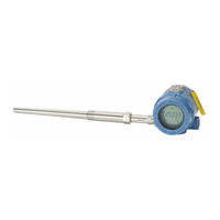
Emerson Rosemount 3144P Reference Manual (236 pages)
Temperature Transmitter with Rosemount X-well Technology
Brand:
Emerson
| Category:
Transmitter
| Size: 14.31 MB
Table of Contents
Table of Contents
3
Section 1 Introduction
11
Using this Manual
11
Transmitter
11
Rosemount 3144P Revisions
12
Confirm HART Revision Capability
15
Section 2 Installation
17
Safety Messages
17
Installation Considerations
18
General
18
Electrical
18
Environmental
18
Moist or Corrosive Environments
19
Location and Position
19
Software Compatibility
20
Commissioning
20
Setting the Loop to Manual
20
Set the Switches
21
Mounting
23
Typical North American Installation
24
Typical European Installation
25
Rosemount X-Well ™ Installation
26
In Conjunction with a Rosemount 333 HART Tri-Loop™ (HART/4-20 Ma Only)
27
LCD Display
29
Multichannel Installation (HART/4-20 Ma Only)
30
Wiring
30
HART/4-20 Ma
30
Foundation Fieldbus
33
Sensor Connections
33
Power Supply
34
Surges/Transients
35
Grounding
35
Transmitter Housing
37
Overview
39
Field Communicator
40
Updating the HART Communication Software
40
Safety Messages
40
Device Dashboard Menu Tree
42
Device Dashboard Fast Key Sequences
48
Review Configuration Data
49
Check Output
49
Analog Output
50
Configuration
50
Variable Mapping
50
Sensor Configuration
50
Change Type and Connections
51
Sensor 1 Serial Number
51
Sensor 2 Serial Number
52
2-Wire RTD Offset
52
Terminal (Body) Temperature
52
Dual-Sensor Configuration
52
Rosemount X-Well Technology Configuration
98
Device Output Configuration
100
Process Variable Damping
101
Alarm and Saturation
102
Device Information
103
Master Reset
104
Intermittent Threshold
105
Open Sensor Holdoff
106
Use with the HART Tri-Loop
107
Calibration Frequency
127
Trim the Transmitter
128
Sensor Input Trim
129
Active Calibrator and EMF Compensation
130
Transmitter-Sensor Matching
131
D/A Output Trim or Scaled Output Trim
137
Troubleshooting
138
LCD Display
142
Overview
143
Device Description
144
Link Active Scheduler (LAS)
145
Resource Block (Index Number 1000)
146
Sensor Transducer Block (Index Number 1100)
147
Resource Block
148
Plantweb ™ Alerts
149
Recommended Actions for Plantweb Alerts
152
Recommended Actions for Field Diagnostics Per NE107
153
Sensor Transducer Block
154
Sensor Transducer Block Diagnostics
155
LCD Display Transducer Block
156
LCD Display Transducer Block Diagnostics
157
Hot Backup Transducer
158
Manual Mode
160
Filtering
164
Advanced Features
165
Analog Input Diagnostics
166
Operation
167
Advanced Diagnostics
169
Statistical Process Monitoring (SPM)
171
SPM Configuration
172
Troubleshooting Guides
173
LCD Display
177
Safety Messages
179
Sensor Checkout
180
Return of Materials
181
Rev JA April
182
SIS Certification
183
Operation and Maintenance
185
Comprehensive Proof Test 2
186
Visual Inspection
187
Spare Parts
187
A.1.1 Functional Specifications
189
A.1.3 Performance Specifications
190
Wiring Diagram
195
Temperature Limits
196
Function Blocks
198
A.4 Dimensional Drawings
199
A.5 Ordering Information
204
A.5.1 How to Order Rosemount X-Well Technology
208
A.6 Spare Parts List
209
Standard Configuration
210
B.1 European Directive Information
213
April
214
Emerson Rosemount 3144P Reference Manual (152 pages)
Temperature Transmitter
Brand:
Emerson
| Category:
Transmitter
| Size: 3.89 MB
Table of Contents
Table of Contents
5
Overview
9
Manual
9
Transmitter
10
Considerations
10
General
10
Electrical
10
Environmental
11
Moist or Corrosive Environments
11
Mounting
12
Software Compatibility
12
Return of Materials
13
3144P Revisions
14
Safety Messages
15
Commissioning
16
Setting the Loop to Manual
16
Set the Switches
17
Mounting
18
Installation
20
Typical North American Installation
20
Typical European Installation
21
In Conjunction with a Rosemount 333 HART Tri-Loop
22
LCD Display
23
Multichannel Installation (HART / 4-20 Ma Only)
24
Wiring
24
HART / 4-20 Ma
24
Foundation
27
Sensor Connections
28
Power Supply
28
Surges/Transients
29
Grounding
29
Overview
33
Safety Messages
33
Field Communicator
34
Updating the HART Communication Software
34
Menu Tree
35
Fast Key Sequences
36
Ams
37
Apply AMS Changes
37
Review Configuration Data
37
Check Output
38
Configuration
38
Device Output Configuration
46
Device Information
50
Measurement Filtering
51
Diagnostics and Service
53
Transmitter Diagnostics Logging
55
Multidrop Communication
55
Use with the HART Tri-Loop
56
Calibration
59
Trim the Transmitter
59
Sensor Input Trim
60
Transmitter-Sensor Matching
63
D/A Output Trim or Scaled Output Trim
64
Output Trim
64
Scaled Output Trim
64
Troubleshooting
66
HART / 4-20 Ma
66
LCD Display
69
AMS Software (HART / 4-20 Ma Only)
70
AMS Screens
72
Spare Parts
73
Overview
75
Foundation
75
Safety Messages
75
Configuration
75
General Block Information
76
Device Description
76
Node Address
76
Modes
76
Link Active Scheduler
77
Block Instantiation
77
Capabilities
78
FOUNDATION Fieldbus Function Blocks
78
Resource Block
79
FEATURES and FEATURES_SEL
79
Plantweb ™ Alerts
81
Recommended Actions for Plantweb Alerts
83
Resource Block Diagnostics
83
Sensor Transducer Block
84
Damping
84
Sensor Transducer Block Diagnostics
84
LCD Transducer Block
85
Custom Meter Configuration
86
Self Test Procedure for the LCD
87
LCD Transducer Block Diagnostics
87
Analog Input (AI)
88
Simulation
88
Configure the AI Block
88
Filtering
91
Process Alarms
91
Status
92
Advanced Features
92
Analog Input Diagnostics
93
Operation
94
Overview
94
Trim the Transmitter
94
Statistical Process Monitoring (SPM)
96
SPM Configuration
97
Troubleshooting Guides
99
Foundation
102
LCD Display
103
Safety Messages
105
Maintenance
106
Test Terminal
106
Sensor Checkout
106
Electronics Housing
106
Safety Messages
109
Certification
109
3144P Safety-Certified Identification
109
Installation
109
Commissioning
110
Configuration
110
Operation and Maintenance
111
Proof Test
111
Inspection
112
Specifications
112
Failure Rate Data
112
Product Life
112
Spare Parts
112
Overview
113
Safe Failure Fraction
114
Installation
114
Switches
114
Changing Switch Position
114
Proof Test
116
HART and FOUNDATION
117
Functional Specifications
117
Physical Specifications
117
Performance Specifications
118
HART / 4-20 Ma Specifications
122
Foundation
125
Dimensional Drawings
126
Ordering Information
130
Rosemount 3144P with HART / 4-20 Ma
135
Approved Manufacturing Locations
135
European Union Directive Information
135
Hazardous Locations Installations
135
Rosemount 3144P with F
140
Approved Manufacturing Locations
140
European Union Directive Information
140
Hazardous Locations Installations
140
OUNDATION Fieldbus
140
Advertisement
Emerson Rosemount 3144P Reference Manual (110 pages)
Smart Temperature Transmitter
Brand:
Emerson
| Category:
Transmitter
| Size: 8.23 MB
Table of Contents
Table of Contents
5
Using this Manual
9
Getting Acquainted with the Transmitter
10
Software Compatibility
10
Return of Materials
11
Model 3144P and Models 3144 / 3244MV Differences
11
Using the Manual with the QIG
12
Step 1: Configure (Bench Calibration)
12
Step 2: Set the Switches
12
Step 3: Mount the Transmitter
12
Step 6: Safety Instrumented System
12
Safety Messages
13
Warnings
13
Commissioning: on the Bench or in the Loop
14
Considerations
15
General
15
Electrical
15
Mechanical
15
Environmental
15
Temperature Effects
15
Considering Housing Rotation
16
Housing Rotation
16
Terminal Side of Electronics Housing
16
Circuit Side of Electronics Housing
16
Set the Switches
17
Failure Mode Switch
17
Transmitter Security Switch
17
Failure Mode and Security Switch Locations
17
Changing the Position of the Failure Mode or Security Switch
17
Without a LCD Meter
17
With a LCD Meter
18
Mounting and Installation
18
Moist or Corrosive Environments
18
Typical North American Installation
20
Typical European Installation
21
Installation in Conjunction with a Model 333 HART Tri-Loop
22
Installing the LCD Meter
23
Connect the Wiring and Power up
24
Field Wiring
24
Power/Current Loop Connections
24
Grounding
25
Shielding
25
Shielding Recommendations
25
Transmitter Housing
26
Surges/Transients
27
Multichannel Installations
27
Sensor Connections
27
RTD or Ohm Inputs
28
Thermocouple or Millivolt Inputs
28
Power Supply
29
Safety Messages
31
Commissioning
31
Warnings
31
Communication Tool
32
Using a Model 275 HART Communicator
32
Connections and Hardware
33
Basic Features
33
Action Keys (See Figure 3-2)
34
Function Keys (See Figure 3-2)
34
Alphanumeric and Shift Keys (See Figure 3-2))
34
Fast Key Sequences
35
Menus and Functions
35
Main Menu
35
Online Menu
36
Configure the Transmitter
37
HART Menu Tree
37
Fast Key Sequences
38
Review Configuration Data
39
Review
39
Check Output
39
Process Variables
39
Configuration
39
Variable Mapping
39
Sensor Configuration
40
Change Type and Connections
40
Transmitter-Sensor Matching
40
Output Units
41
Sensor 1 Serial Number
41
Sensor 2 Serial Number
42
2-Wire RTD Offset
42
Terminal Temperature
42
Dual-Sensor Configuration
42
Differential Temperature
42
Average Temperature
43
First-Good Configuration
44
Hot Backup Configuration
45
Drift Alert Configuration
46
Device Output Configuration
47
PV Range Values
47
Process Variable Damping
47
Alarm and Saturation
48
HART Output
49
LCD Meter Options
49
Device Information
49
Tag
50
Date
50
Descriptor
50
Message
50
Measurement Filtering
50
50/60 Hz Filter
50
Intermittent Sensor Detect
50
Intermittent Threshold
51
Intermittent Sensor Detect (Advanced Feature)
51
Transmitter Behavior with Intermittent Sensor Detect on
51
Transmitter Behavior with Intermittent Sensor Detect off
52
Open Sensor Holdoff
52
Diagnostics and Service
52
Test Device
52
Loop Test
52
Trim the Transmitter
53
Sensor Trim
53
Active Calibrator and EMF Compensation
55
Output Trim or Scaled Output Trim
56
Output Trim
56
Scaled Output Trim
57
Multidrop Communication
57
Setting the Loop to Manual
58
Commissioning the Transmitter
58
Use with the HART Tri-Loop
58
Set the Transmitter to Burst Mode
58
Set Process Variable Output Order
58
Special Considerations
59
Using the Tri-Loop to Detect Sensor Drift Alert
59
Safety Messages
61
Warning
61
Hardware
62
Diagnostics
62
Maintenance
63
Test Terminal
63
Sensor Checkout
63
Disassembling the Electronics Housing
64
Removing the Electronics Module
64
Transmitter Security and Failure Mode Switches
64
Assembling the Electronics Housing
65
Replacing the Electronics Module
65
LCD Meter
65
Diagnostic Messages
65
Model 275 HART Communicator
67
Diagnostic Messages
67
Specifications
71
Functional
71
Physical
73
Performance
74
Dimensional Drawings
77
Ordering Information
79
Configuration
81
Standard
81
Custom
82
Custom Transmitter Configuration (Option Code C1
82
Transmitter-Sensor Matching Trim to Specific Rosemount RTD Calibration Schedule (Option Code C2
82
Five-Point Calibration (Option Code C4
82
Trim to Special Sensor (Option Code C7
82
NAMUR Compliant Operation (Option Codes A1 and CN
83
Low Alarm (Option Code C8
83
50 Hz Line Voltage Filter (Option Code F5
83
Custom - Dual-Sensor Option
83
Hot Backup Configuration (Option Code U1
83
Average Temperature with Hot Backup and Drift Alert
84
(Option Code U2
84
Two Independent Sensors (Option Code U4
84
Differential Temperature (Option Code U5
84
Average Temperature (Option Code U6
85
Additional Options
85
Calibration Certificate (Option Code Q4
85
Quality Certification for Safety Instrumented Systems
85
(Option Code QS
85
Mounting Brackets (Option Codes B4 and B5
85
Assembly Options (Option Code X1, X2, and X3
85
External Ground Lug Assembly (Option Code G1
86
Transient Protection (Option Code T1
86
LCD Meter (Option Code M5
87
Hazardous Locations Installations
89
Hazardous Locations Certifications
89
Installation Drawings
93
Overview
101
Failure Rate Data
102
Model 3144P with and Without a RTD
102
Model 3144P with and Without a Thermocouple
102
Installation
103
Switches
103
Failure Mode Switch
103
Transmitter Security Switch
103
Changing Switch Position
103
Without a LCD Meter
103
With a LCD Meter
104
Emerson Rosemount 3144P Reference Manual (204 pages)
Temperature Transmitter
Brand:
Emerson
| Category:
Transmitter
| Size: 10.75 MB
Table of Contents
Table of Contents
3
Chapter 1 Introduction
5
Using this Manual
5
Rosemount 3144P Revisions
6
Confirm HART Revision Capability
10
Chapter 2 Installation
11
Installation Considerations
11
Commissioning
13
Mounting
16
Installation
17
Wiring
23
Foundation Fieldbus
27
Power Supply
28
Grounding
29
Wire and Apply Power
32
Chapter 3 HART Commissioning
33
Overview
33
Confirm HART Revision Capability
33
Safety Messages
34
Field Communicator
34
Review Configuration Data
44
Check Output
44
Configuration
44
Rosemount X-Well Technology Configuration
99
Device Output Configuration
102
Device Information
104
Measurement Filtering
106
Diagnostics and Service
108
Multidrop Communication
109
Use with the HART Tri-Loop
110
Configure Thermocouple Degradation in Guided Setup
113
Configure Thermocouple Degradation in Manual Setup
118
Active Thermocouple Degradation Alerts
123
Minimum/Maximum Tracking Diagnostic
128
Calibration
136
Trim the Transmitter
137
Output Trim or Scaled Output Trim
147
Troubleshooting
148
FOUNDATION Fieldbus Configuration
157
Overview
157
Safety Messages
157
Device Description
157
Node Address
158
Modes
158
Link Active Scheduler (LAS)
159
Capabilities
159
FOUNDATION Fieldbus Function Blocks
160
Resource Block
162
Analog Input (AI)
175
Operation
182
Troubleshooting Guides
188
Operation and Maintenance
193
Safety Messages
193
Maintenance
193
Return of Materials
195
Safety Instrumented Systems (SIS) Requirements
197
SIS Certification
197
Safety Certified Identification
197
Installation
197
Configuration
198
Operation and Maintenance
200
Specifications
201
Spare Parts
202
Appendix A Reference Data
203
Product Certifications
203
Ordering Information, Specifications, and Drawings
203
Emerson Rosemount 3144P Quick Start Manual (40 pages)
Temperature Transmitter with HART Protocol and Rosemount X-well Technology
Brand:
Emerson
| Category:
Transmitter
| Size: 2.66 MB
Table of Contents
Table of Contents
2
About this Guide
3
System Readiness
5
Verify Configuration
6
Set the Switches
10
Mount the Transmitter
11
Wire and Apply Power
13
Perform a Loop Test
18
Safety Instrumented Systems (SIS)
19
Product Certifications
20
Emerson Rosemount 3144P Quick Start Manual (40 pages)
Temperature Transmitters
Brand:
Emerson
| Category:
Transmitter
| Size: 2.18 MB
Table of Contents
Table of Contents
2
About this Guide
3
Mount the Transmitter
5
Wire and Apply Power
7
Verify Tagging
12
Product Certifications
17
Emerson Rosemount 3144P Quick Start Manual (36 pages)
Temperature Transmitters with Foundation Fieldbus Protocol
Brand:
Emerson
| Category:
Transmitter
| Size: 1.85 MB
Table of Contents
Table of Contents
2
About this Guide
3
Mount the Transmitter
5
Wire and Apply Power
7
Verify Tagging
12
Product Certifications
16
Emerson Rosemount 3144P Quick Start Manual (28 pages)
Temperature, with HART Protocol and Rosemount X-well Technology
Brand:
Emerson
| Category:
Transmitter
| Size: 1.16 MB
Table of Contents
Table of Contents
2
System Readiness
3
Verify Configuration
3
Set the Switches
6
Mount the Transmitter
6
July
7
Wire and Apply Power
9
Ground the Transmitter
11
Perform a Loop Test
13
Safety Instrumented System (SIS)
13
Product Certifications
14
Eu Declaration of Conformity
24
Emerson Rosemount 3144P Quick Start Manual (24 pages)
Temperature Transmitter with HART Protocol
Brand:
Emerson
| Category:
Transmitter
| Size: 1.91 MB
Table of Contents
Table of Contents
2
System Readiness
3
Verify Configuration
3
Set the Switches
5
Mount the Transmitter
6
Wire and Apply Power
7
Perform a Loop Test
11
Safety Instrumented System (SIS)
12
Product Certifications
13
Advertisement
Related Products
Emerson Rosemount Ultrasonic 3107
Emerson Rosemount 3100 Series
Emerson Rosemount 3152
Emerson Rosemount 3153
Emerson Rosemount 3154
Emerson Rosemount 3101
Emerson Rosemount 3102
Emerson Rosemount 3105
Emerson Rosemount 3308
Emerson Rosemount 3051L
Emerson Categories
Controller
Control Unit
Transmitter
Measuring Instruments
Fan
More Emerson Manuals
Login
Sign In
OR
Sign in with Facebook
Sign in with Google
Upload manual
Upload from disk
Upload from URL