Sign In
Upload
Manuals
Brands
Emerson Manuals
Transmitter
Rosemount 3105
Emerson Rosemount 3105 Manuals
Manuals and User Guides for Emerson Rosemount 3105. We have
4
Emerson Rosemount 3105 manuals available for free PDF download: Reference Manual, Quick Start Manual
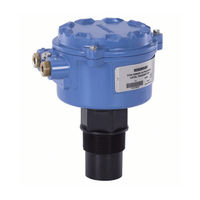
Emerson Rosemount 3105 Reference Manual (240 pages)
Ultrasonic Liquid Level Transmitters
Brand:
Emerson
| Category:
Transmitter
| Size: 11.27 MB
Table of Contents
Table of Contents
5
Safety Messages
13
Manual Overview
13
Service Support
14
Product Recycling/Disposal
14
The Rosemount 3101, 3102, and 3105
15
Theory of Operation
16
Components of the Transmitter
16
System Architecture
18
Safety Messages
19
Considerations before Installation
20
Safety Considerations
20
Environmental Considerations
21
Mechanical Installation
22
Mounting Considerations
22
Consider Liquid Surface Conditions
22
Consider In-Tank Effects
23
Mounting the Transmitter above the Liquid Surface
24
Open Channel Flow Installations (the 3102/3105)
26
Electrical Installation
28
Connecting the Cable(S) to the Transmitter
28
Connecting the Cable Wires to the Rosemount 3101
29
Connecting the Cable Wires to the Rosemount 3102
30
Connecting the Cable Wires to the Rosemount 3105
31
Remote Temperature Sensor
33
Wiring to Allow HART Communications
33
Lightning / Surge Protection and Other Loop Devices
33
Safety Messages
35
Programming the Rosemount 3101, 3102, and 3105 Transmitters
36
Integral Display and Buttons
36
What Happens When Powering up the Transmitter
37
Considerations before Starting the Programming
37
Programming the 3101 Using the Integral Display and Buttons
38
Display Units (on the 3101)
38
First Measurements (on the 3101)
39
Setting the Bottom Reference (on the 3101)
40
Setting 4 Ma and 20 Ma Levels (on the 3101)
40
Setting the Output Damping (on the 3101)
42
Selecting the Lost Echo Action (on the 3101)
43
Setting 4 Ma and 20 Ma Levels Using Ranging (on the 3101)
44
Learn about Echoes from False Targets (on the 3101)
45
Do Final Checks
46
What Happens When a Power Failure Occurs
46
Programming the 3102 and 3105 Using the Integral Display and Buttons
47
Overview of Programming the 3102 or the 3105
47
Selecting the Duty (on the 3102/3105)
47
Selecting the Units of Measurement (on the 3102/3105)
48
Setting the Correct Bottom Reference (on the 3102/3105)
50
Selecting a Profile (on the 3102/3105)
51
Power Factor for the Flow Law (on the 3102/3105)
55
Setting the Scaling Factor (on the 3102/3105)
56
Maximum Level Entry (on the 3102/3105)
57
Maximum Flow Entry (on the 3102/3105)
58
Maximum Contents (Volume) Entry (on the 3102/3105)
59
Setting the 4 Ma Point (on the 3102/3105)
60
Setting the 20 Ma Point (on the 3102/3105)
61
Setting the Output Damping (on the 3102/3105)
62
Selecting the Lost Echo Action (on the 3102/3105)
63
Setting the Relay on and off Points (on the 3102)
64
Setting the 4 and 20 Ma Levels Using Ranging (on the 3102/3105)
66
Do Final Checks
67
What Happens When a Power Failure Occurs
67
Rev CB February
68
Safety Messages
69
Servicing
70
Diagnostics for the 3101
70
General Troubleshooting
70
Error Messages
70
Diagnostics for the 3102 and the 3105
71
General Troubleshooting (on the 3102/3105)
71
Fault and Alarms (on the 3102/3105)
71
Diagnostic Data (on the 3102/3105)
72
Loop Test (on the 3102/3105)
73
Engineering Menu for the 3102 and 3105
74
Accessing the Engineering Menu (on the 3102/3105)
74
Setting the Threshold (on the 3102/3105)
75
Setting Lost Echo Time (on the 3102/3105)
76
Setting the Dead Band (on the 3102/3105)
77
Setting the Frequency (on the 3102/3105)
78
Setting the Pulse Repetition Frequency (on the 3102/3105)
79
Setting Valid Echo Count (on the 3102/3105)
80
Setting Spike Rejection (on the 3102/3105)
81
Learn about Echoes from False Targets (on the 3102/3105)
81
Setting the Ambient Temperature (on the 3102/3105)
83
Temperature Calibration (on the 3102/3105)
84
Loading Factory Default Values (on the 3102/3105)
85
Changing the Base Units (on the 3102/3105)
86
False Echoes under Certain Ambient Operating Conditions
87
(On the 3102/3105)
87
Specifications
89
General
89
Measuring Performance
89
A.1 Specifications
89
Display and Configuration
90
Electrical
91
A.1.4 Electrical
91
Materials
92
Mechanical
92
A.1.5 Materials
92
Measuring
93
Environment
93
A.1.7 Measuring
93
Temperature and Pressure Ratings
94
Load Limitations
95
A.1.10 Load Limitations
95
A.2 Dimension Drawings
96
Dimension Drawings
96
Ordering Information
99
Rosemount 3101 Ordering Information
99
A.3 Ordering Information
99
Rosemount 3102 Ordering Information
100
The Rosemount 3105 Level Transmitter
101
Spare Parts and Accessories
102
Spare Parts and Accessories for the 3101/3102/3105
102
B.1 Manufacturing Location
103
Manufacturing Location
103
European Union Directive Information
103
Non-Hazardous Location Certifications
104
American and Canadian Certifications
104
Hazardous Locations Certifications
105
American and Canadian Certifications
105
European Certification
105
International Certifications
106
B.4.3 International Certifications
106
B.5 Approval Drawings
109
Approval Drawings
109
Menus on the 3101
114
Menus on the 3102 and the 3105
115
D.1 Introduction
121
Introduction
121
Menus and Parameters
121
Introduction
125
Menus and Parameters
125
Overview of Programming the 3102 and 3105
129
Using a Rosemount 3490 Series Control Unit
129
Using a Field Communicator or AMS Device Manager
129
Command Parameters
130
Base Units
130
F.2.1 Base Units
130
Set as Empty
132
F.2.2 Set as Empty
132
Present Depth
133
F.2.3 Present Depth
133
Learn False Echo
134
Auto Tank Map
136
Simulation of PV
137
F.2.6 Simulation of PV
137
Restart Device
138
F.2.7 Restart Device
138
Load Defaults
139
F.2.8 Load Defaults
139
Simulate Current Output
140
Trim 4 Ma / Trim 20 Ma
141
Configuration Parameters
143
Message (P000)
143
F.3.1 Message (P000)
143
Tag (P001)
144
F.3.2 Tag (P001)
144
Descriptor (P002)
145
F.3.3 Descriptor (P002)
145
Final Assembly Number (P004)
146
Serial Number (P005)
147
Bottom Reference (P010)
148
Upper Blanking (P023)
150
Lower Blanking (P063)
152
Distance Offset (P060)
153
Level Offset (P069)
154
Tank Shape / Non-Linear Profile (P011)
155
Contents (Volume) Measurement
157
Flow Measurement
162
F.3.13 Flow Measurement
162
Primary Variable Units (P012)
165
Scale Factor / K-Factor (P013)
166
Profile Height / Power Factor (P014)
168
Profile Points 1 to 10 (P030 to P039)
170
Upper Range Value (P015)
171
Lower Range Value (P016)
172
Damping (P020)
174
F.3.20 Damping (P020)
174
Relay 1 Mode (P070) on the Rosemount 3102
175
RL1 PV on Point (P071) on the Rosemount 3102
177
RL1 PV off Point (P072) on the Rosemount 3102
178
Relay 2 Mode (P073) on the Rosemount 3102
179
RL2 PV on Point (P074) on the Rosemount 3102
180
RL2 PV off Point (P075) on the Rosemount 3102
181
Lost Echo Delay (P021)
182
Lost Echo Action (P022)
184
Speed of Sound (P024)
186
Temperature (P025)
188
F.3.30 Temperature (P025)
188
Set Threshold (P026)
189
Transmit Power Control (P040)
190
Pulse Repeat (P041)
191
Echoes Needed (P042)
192
Threshold 1 Time (P043)
193
Threshold 1 Size (P048)
194
Target Pulses (P044)
195
Target Frequency (P045)
196
Spike Rejection (P049)
198
False Echo Data (P081 to P088)
199
Clear False Echoes (P089)
199
F.3.41 Clear False Echoes (P089)
200
Transducer Material (P970)
201
Poll Address (D951)
202
Maximum Temperature (P046)
203
Minimum Temperature (P047)
204
Date (P003)
205
F.3.46 Date (P003)
205
Monitoring and Diagnostic Parameters
206
Process Value / Primary Variable (PV) (D900)
206
Level / Secondary Variable (SV) (D901)
207
Distance / Tertiary Variable (TV) (D902)
208
Temperature / Fourth Variable (FV) (D903)
209
Of Current Output (D905)
210
Current Output (D906)
210
F.4.6 Current Output (D906)
211
Distance (D910)
212
F.4.7 Distance (D910)
212
Echo Size (D911)
213
Echo Success (D912)
214
Target Echoes (D913)
215
Speed of Sound (D914)
216
Temperature for Sos Calculation (D915)
217
Frequency (D916)
218
F.4.13 Frequency (D916)
218
Threshold in Use (D917)
219
Pulses in Use (D918)
220
Transmit Power (D919)
221
Model Code (D949)
222
Hardware Rev. (D952)
223
Software Revision (D953)
224
Manufacturer (D960)
225
F.4.20 Manufacturer (D960)
225
Unique Device ID (D961)
226
HART Revision (D962)
227
Transmitter Specific Command Revision (D963)
228
Preambles (D964)
229
F.4.24 Preambles (D964)
229
Transmitter Flags (D965)
230
Primary Variable Trend
231
Temperature Trend
231
Distance and Echo Size Trend
232
Advertisement
Emerson Rosemount 3105 Reference Manual (144 pages)
Ultrasonic Liquid Level Transmitters
Brand:
Emerson
| Category:
Transmitter
| Size: 1.24 MB
Table of Contents
Table of Contents
5
Manual Overview
10
Service Support
11
Theory of Operation
13
Components of the Transmitter
14
System Architecture
15
Before You Install
18
General Considerations
18
Mechanical Installation
19
Mounting Considerations
19
Liquid Surface Conditions
20
In-Tank Effects
20
Mounting the Transmitter above the Liquid Surface
21
Open Channel Flow Installations (the 3102/3105)
23
Electrical Installation
25
Connecting the Transmitter
25
Wiring for the Rosemount 3101
26
Wiring for the Rosemount 3102
27
Wiring for the Rosemount 3105
28
Remote Temperature Sensor
30
Wiring to Allow HART
30
Lightning / Surge Protection and Other Loop Devices
30
Overview
32
Display and Push-Buttons
32
Power up
33
Before Programming
33
Programming the Rosemount 3101
34
Display Units (the 3101)
34
First Measurements (the 3101)
35
Setting the Bottom Reference (the 3101)
36
Setting 4 Ma and 20 Ma Levels (the 3101)
36
Setting the Output Damping (the 3101)
37
Selecting the Action on Alarm Condition (the 3101)
38
Setting 4 Ma and 20 Ma Levels Using Ranging (the 3101)
39
Learn about Echoes from False Targets (the 3101)
40
Changing to Distance Mode (the 3101)
41
Programming the 3102 and the 3105
42
Overview (the 3102/3105)
42
Selecting the Duty (the 3102/3105)
42
Selecting the Units of Measurement (the 3102/3105)
43
Setting the Correct Bottom Reference (the 3102/3105)
44
Selecting a Profile (the 3102/3105)
45
Power Factor for the Flow Law (the 3102/3105)
49
K-Factor for the Flow Law (the 3102/3105)
49
Maximum Level Entry (the 3102/3105)
50
Maximum Flow Entry (the 3102/3105)
51
Maximum Contents (Volume) Entry (the 3102/3105)
52
Setting the 4 Ma Point (the 3102/3105)
52
Setting the 20 Ma Point (the 3102/3105)
53
Setting the Output Damping (the 3102/3105)
54
Selecting the Alarm Condition Action (the 3102/3105)
55
Setting the Relay on and off Points (the 3102)
56
Setting the 4 and 20 Ma Levels Using Ranging (the 3102 and the 3105)
57
Final Checks
58
Power Failure
58
Safety Messages
59
Servicing
60
Diagnostics for the 3101
60
General Troubleshooting
60
Error Messages
60
Diagnostics for the 3102 and the 3105
61
General Troubleshooting (the 3102/3105)
61
Diagnostic Data (the 3102/3105)
61
Loop Test (the 3102/3105)
62
Engineering Menu for the 3102 and 3105
64
Accessing the Engineering Menu (the 3102/3105)
64
Setting the Threshold (the 3102/3105)
64
Setting Lost Echo Time (the 3102/3105)
65
Setting the Dead Band (the 3102/3105)
66
Setting the Frequency (the 3102/3105)
67
Setting the Pulse Repetition Frequency (the 3102/3105)
68
Setting Valid Echo Count (the 3102/3105)
68
Setting Spike Rejection (the 3102/3105)
69
Learn about Echoes from False Targets (the 3102/3105)
70
Setting the Ambient Temperature (the 3102/3105)
71
Temperature Calibration (the 3102/3105)
72
Changing the Base Units (the 3102/3105)
74
Specifications
75
Temperature and Pressure Ratings
77
Load Limitations
77
Dimensional Drawings
78
Ordering Information
80
The 3101, Level of Liquids
80
The 3102, Level, Content (Volume) or Flow of Liquids
81
The 3105, Level, Content (Volume) or Flow of Liquids
82
Spare Parts
83
Accessories for the Rosemount 3101/3102/3105
83
Safety Messages
85
EU Conformity
86
Non-Hazardous Location Certifications
86
Factory Mutual (FM) Ordinary Location Certification
86
Canadian Standards Association (CSA) Ordinary Location Certification
86
Hazardous Locations Certifications
87
Factory Mutual (FM) Approvals
87
Canadian Standards Association (CSA) Approvals
88
ATEX Intrinsically Safe Approval
89
Iecex Intrinsically Safe Approval
90
National Supervision and Inspection Centre (NEPSI) Intrinsically
91
Safe Approval
91
Approval Drawings
93
Menus on the 3101
100
Menus on the 3102 and the 3105
101
Introduction
105
Introduction
109
Safety Messages
109
Introduction
115
Transmitter Action Parameters (the 3102 and 3105
116
Parameter: BASE UNITS
116
Parameter: SET as EMPTY
116
Parameter: PRESENT DEPTH
116
Parameter: LEARN FALSE ECHO
117
Parameter: AUTO TANK MAP
117
Parameter: SIMULATION
117
Parameter: RESTART DEVICE
117
Parameter: DEFAULTS
117
Parameter: FACTORY USE
118
Transmitter P*** Parameters (the 3102 and 3105
119
P000 (Message
119
P001 (Tag Number
119
P002 Description
119
P004 (Final Assembly Number
119
P005 (Serial Number
119
P010 (Bottom Reference
119
P011 (Tank Shape
120
P012 (PV Units
126
P013 (PV Scale Factor
126
P014 (Profile Height or Power
127
P015 (Upper Range Value
127
P016 (Lower Range Value
127
P020 (Damping / Smoothing Time
128
P021 (Lost Echo Delay
128
P022 (Lost Echo Action
129
P023 (Top Blanking Distance
129
P024 (Speed of Sound
130
P025 (Temperature
131
P026 (Threshold
131
P030 to P039 (Profile Points
131
P040 (Transmit Power Control
131
P041 (Pulse Repeat
132
P042 (Echoes Needed
132
P043 (Threshold 1 Time
132
P044 (Target Pulses
132
P045 (Target Frequency
133
P048 (Threshold 1 Size
133
P049 (Spike Reject
133
P060 (Distance Offset
133
P063 (Bottom Blanking Distance
133
P069 (Level Offset
133
P070 to P072 (Relay 1 Setting-Up
134
P073 to P075 (Relay 2 Setting-Up
135
P081 to P088 (False Echo Data
135
P089 (Clear False Echoes
135
P970 (TX Material
135
Transmitter D*** Parameters (the 3102 and 3105
136
D900 (Xmtr PV
136
D901 (Level, SV
136
D902 (Distance, TV
136
D903 (Temperature, FV
136
D905 (% of Current Output
136
D906 (Current Output
137
D910 (Target Range
137
D911 (Echo Size
137
D912 (Echo Success
137
D913 (Target Echoes
137
D914 (Speed of Sound
137
D915 (Temperature
138
D916 (Frequency
138
D917 (Threshold in Use
138
D918 (Pulses in Use
138
D919 (Transmit Power
138
D949 (Model Code
138
D951 (Poll Address
138
D952 (Hardware Revision
138
D953 (Software Revision
138
D960 (Manufacturer
138
D962 (HART Revision
139
D963 (Txr Specific Command Revision
139
D964 (Preambles
139
D965 (Flags
139
Emerson Rosemount 3105 Quick Start Manual (48 pages)
Ultrasonic Liquid Level Transmitters
Brand:
Emerson
| Category:
Transmitter
| Size: 3.48 MB
Table of Contents
Table of Contents
2
About this Guide
3
The Rosemount 3101, 3102, and 3105
5
Considerations before Installation
7
Electrical Installation
10
Configuring the Transmitter
21
Product Certifications
36
Advertisement
Emerson Rosemount 3105 Quick Start Manual (32 pages)
Ultrasonic Liquid Level Transmitters
Brand:
Emerson
| Category:
Transmitter
| Size: 4.28 MB
Table of Contents
Theory of Operation
3
Considerations before Installation
4
Safety Considerations
4
Environmental Considerations
5
Mounting Considerations
6
Electrical Installation
7
Connecting the Cable(S) to the Transmitter
7
Bracket Mounting
10
Installation Instructions
10
Configuring the Transmitter
14
Product Certifications
24
European Union Directive Information
24
Factory Mutual (FM) Approvals
24
Canadian Standards Association (CSA) Approvals
25
Advertisement
Related Products
Emerson Rosemount 3144P
Emerson Rosemount Ultrasonic 3107
Emerson Rosemount 3100 Series
Emerson Rosemount 3152
Emerson Rosemount 3153
Emerson Rosemount 3154
Emerson Rosemount 3101
Emerson Rosemount 3102
Emerson Rosemount MultiVariable 3051SFC
Emerson Rosemount MultiVariable 3051SFA
Emerson Categories
Controller
Control Unit
Transmitter
Measuring Instruments
Fan
More Emerson Manuals
Login
Sign In
OR
Sign in with Facebook
Sign in with Google
Upload manual
Upload from disk
Upload from URL