Emerson Rosemount 3144P Quick Start Manual
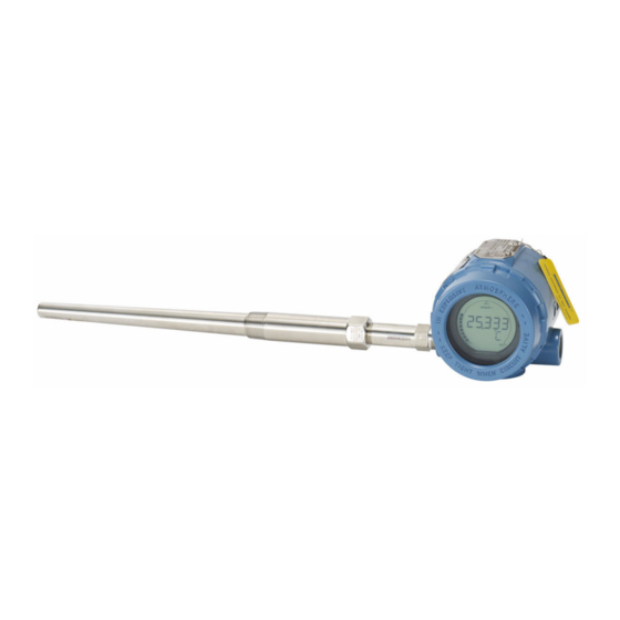
Temperature transmitter with hart protocol and rosemount x-well technology
Hide thumbs
Also See for Rosemount 3144P:
- Reference manual (236 pages) ,
- Quick start manual (40 pages) ,
- Reference manual (252 pages)

Related Manuals for Emerson Rosemount 3144P


Summary of Contents for Emerson Rosemount 3144P
- Page 1 Quick Start Guide 00825-0100-4021, Rev PB March 2021 ™ Rosemount 3144P Temperature Transmitter ® with HART Protocol and Rosemount ™ X-well Technology...
-
Page 2: Table Of Contents
Quick Start Guide March 2021 Contents About this guide...........................3 System readiness......................... 5 Verify configuration........................6 Set the switches......................... 10 Mount the transmitter........................11 Wire and apply power........................ 13 Perform a loop test........................18 Safety Instrumented Systems (SIS)..................... 19 Product certifications......................... 20 Rosemount 3144P... -
Page 3: About This Guide
March 2021 Quick Start Guide About this guide This guide provides basic guidelines for installing the Rosemount 3144P Transmitter. It does not provide instructions for detailed configuration, diagnostics, maintenance, service, troubleshooting, Explosion-proof, Flameproof, or intrinsically safe (I.S.) installations. Refer to the Rosemount... - Page 4 Physical security is an important part of any security program and fundamental to protecting your system. Restrict physical access by unauthorized personnel to protect end users’ assets. This is true for all systems used within the facility. Rosemount 3144P...
-
Page 5: System Readiness
March 2021 Quick Start Guide System readiness Confirm HART revision capability If using HART based control or asset management systems, confirm the HART capability of those systems prior to transmitter installation. Not all systems are capable of communicating with HART Revision 7 Protocol. You can configure the transmitter for either HART Revision 5 or 7. -
Page 6: Verify Configuration
Reference Manual. Update the Field Communicator software To fully communicate with the Rosemount 3144P Transmitter, you need the latest Field Communicator Field Device Revision Dev v5 or v7, DD v1 or greater. Transmitters equipped with Rosemount X-well Technology require DD revision 3144P Dev. 7 Rev. 1 or greater to view this functionality. - Page 7 March 2021 Quick Start Guide Figure 3-1: Connecting a Communicator to a Bench Loop A. Power/signal terminals B. 250 Ω ≤ R ≤ 1100 Ω C. Power supply Procedure 1. Connect the sensor. See the wiring diagram located on the inside of the housing cover. 2.
- Page 8 1, 8, 2, 3 1, 11, 2, 3 HART lock 2, 2, 9, 2 Intermittent sensor detect 2, 2, 7, 5, 2 2, 2, 7, 5, 2 Lock status 1, 11, 3, 7 Long tag 2, 2, 7, 2 Rosemount 3144P...
- Page 9 March 2021 Quick Start Guide Function HART 5 Fast Keys HART 7 Fast Keys Loop test 3, 5, 1 3, 5, 1 LRV (lower range value) 2, 2, 5, 5, 3 2, 2, 5, 5, 3 Message 2, 2, 7, 1, 4 2, 2, 7, 1, 5 Open sensor holdoff 2, 2, 7, 4...
-
Page 10: Set The Switches
Quick Start Guide March 2021 Set the switches The Rosemount 3144P Transmitter comes with hardware switches to configure alarms and lock the device. Use the following procedures to set the switches. WARNING Enclosure Enclosure covers must be fully engaged to meet explosion-proof requirements. -
Page 11: Mount The Transmitter
March 2021 Quick Start Guide Mount the transmitter Mount the transmitter at a high point in the conduit run to prevent moisture from draining into the transmitter housing. Typical North American installation Procedure 1. Mount the thermowell to the process container wall. 2. - Page 12 9. Insert shielded cable leads through the cable entries into the connection head/transmitter. Connect and tighten cable glands. 10. Connect the shielded cable leads to the connection head terminals (located inside the connection head) and to the sensor wiring terminals (located inside the transmitter housing). Rosemount 3144P...
-
Page 13: Wire And Apply Power
Emerson provides 4-wire sensors for all single-element RTDs. You can use these RTDs in 3- wire configurations by leaving the unneeded leads disconnected and insulated with electrical tape. Transmitter must be configured for a 3-wire RTD in order to recognize an RTD with a compensation loop. - Page 14 2. Connect the positive power lead to the "+" terminal. 3. Connect the negative power lead to the "-" terminal. 4. Tighten the terminal screws. 5. Reattach and tighten the cover. WARNING Enclosure Enclosure covers must be fully engaged to meet explosion-proof requirements. 6. Apply power. Rosemount 3144P...
- Page 15 1 (the most common). Ground the transmitter: option 1 Emerson recommends this option for ungrounded transmitter housing. Procedure 1. Connect signal wiring shield to the sensor wiring shield.
- Page 16 2. Ensure the sensor wiring and signal wiring shields are electrically isolated from the transmitter housing and other grounded fixtures. 3. Ground signal wiring shield at the power supply end. A. Sensor B. Transmitter C. Shield ground points Rosemount 3144P...
- Page 17 March 2021 Quick Start Guide 6.3.2 Ground thermocouple inputs Procedure 1. Ground sensor wiring shield at the sensor. 2. Ensure the sensor wiring and signal wiring shields are electrically isolated from the transmitter housing and other grounded fixtures. 3. Ground signal wiring shield at the power supply end. A.
-
Page 18: Perform A Loop Test
1. From the Home screen, select 3 Service Tools → 5 Simulate → 1 Perform Loop Test → 3 Simulate Alarm. The transmitter will output the alarm current level based on the configured alarm parameter and switch settings. 2. Select 5 End to return the transmitter to normal conditions. Rosemount 3144P... -
Page 19: Safety Instrumented Systems (Sis)
March 2021 Quick Start Guide Safety Instrumented Systems (SIS) For safety certified installations, refer to the Rosemount 3144P Reference Manual. The manual is available electronically on Emerson.com/Rosemount. You can also contact an Emerson representative for the manual. Quick Start Guide... -
Page 20: Product Certifications
A copy of the EU Declaration of Conformity can be found at the end of this guide The most recent revision of the EU Declaration of Conformity can be found at Emerson.com/Rosemount. Ordinary location certification As standard, the device has been examined and tested to determine that the... - Page 21 March 2021 Quick Start Guide 9.3.3 I6 CSA Intrinisic Safety and Division 2 Certificate 1242650 Standards CAN/CSA C22.2 No. 0-M91 (R2001), CAN/CSA-C22.2 No. 94- M91, CSA Std C22.2 No. 142-M1987, CAN/CSA-C22.2 No. 157-92, CSA Std C22.2 No. 213-M1987 Markings Intrinsically Safe for Class I Groups A, B, C, D; Class II, Groups E, F, G;...
- Page 22 500 V insulation test. This must be taken into account during installation. 2. The enclosure may be made from aluminum alloy with a protective polyurethane paint finish; however, care should be taken to protect it from impact or abrasion when located in Zone 0. Rosemount 3144P...
- Page 23 March 2021 Quick Start Guide 9.4.3 N1 ATEX Type n Certificate BAS01ATEX3432X [HART]; Baseefa03ATEX0709X [Fieldbus] Standards EN IEC 60079-0:2018, EN 60079-15:2010 Markings HART: II 3 G Ex nA IIC T5/T6 Gc; T6(-40 °C ≤ T ≤ +50 °C), T5(-40 °C ≤ T ≤...
- Page 24 IEC 60079-0:2011 and IEC 60079-31:2013 Markings Ex tb IIIC T130 °C Db, (-40 °C ≤ T ≤ +70 °C); IP66 Process temperature limits for process temperatures. Specific conditions of use (X): 1. See certificate for ambient temperature range. Rosemount 3144P...
- Page 25 March 2021 Quick Start Guide 2. The non-metallic label may store an electrostatic charge and become a source of ignition in Group III environments. 3. Guard the LCD display cover against impact energies greater than four joules. 4. Flameproof joints are not intended for repair. 5.
- Page 26 500 V electrical strength test as defined in ABNT NBR IEC60079-11. This must be taken into account during installation. 2. The enclosure may be made from aluminum alloy with a protective polyurethane paint finish; however, care should be taken to protect it Rosemount 3144P...
- Page 27 March 2021 Quick Start Guide from impact and abrasion when located in areas that require EPL Ga (Zone 0). INMETRO Intrinsic Safety [Fieldbus/FISCO] Certificate UL-BR 15.0030X Standards ABNT NBR IEC 60079-0:2013, ABNT NBR IEC 60079-11:2013 Markings Ex ia IIC T4 Ga (-60 °C < T <...
- Page 28 Zone 0. 9.8.3 KM Technical Regulation Customs Union (EAC) Flameproof, Intrinsic Safety, and Dust Standards GOST 31610.0-2014, GOST IEC 60079-1-2013, GOST IEC 60079-11-2014, GOST IEC 60079-31-2013 Rosemount 3144P...
- Page 29 March 2021 Quick Start Guide Markings Ex tb IIIC T130 °C Db X (-40 °C ≤ T ≤ +70 °C), IP 66 in addition to markings listed for EM and IM above. Special Condition for Safe Use (X): 1. See certificate for special conditions. Japan 9.9.1 E4 Japan Flameproof...
- Page 30 Process temperatures may exceed the limits defined in Table 9-3 if the temperature of the LCD display cover is verified to not exceed the service temperatures in Table 9-4 and the process temperatures do not exceed the values specified in Table 9-2. Rosemount 3144P...
- Page 31 March 2021 Quick Start Guide Table 9-3: Transmitter with LCD Display Cover Extension length Process temperature [˚C] Dust T4...T1 T130 °C No extension 3-in. extension 6-in. extension 9-in. extension Table 9-4: Transmitter with LCD Display Cover Extension length Service temperature [˚C] Dust T4...T1 T130 °C...
- Page 32 Intended use Det Norske Veritas’ Rules for Classification of Ships, High Speed & Light Craft and Det Norske Veritas’ Offshore Standards Application Table 9-6: Location Classes Temperature Humidity Vibration Enclosure SLL Lloyds Register (LR) type approval Certificate 11/60002 Application Environmental categories ENV1, ENV2, ENV3, and ENV5 Rosemount 3144P...
- Page 33 March 2021 Quick Start Guide 9.14 Installation drawings for intrinsic safety Quick Start Guide...
- Page 34 Quick Start Guide March 2021 Rosemount 3144P...
- Page 35 March 2021 Quick Start Guide Quick Start Guide...
- Page 36 Quick Start Guide March 2021 9.15 Declaration of conformity Rosemount 3144P...
- Page 37 March 2021 Quick Start Guide Quick Start Guide...
- Page 38 Quick Start Guide March 2021 Rosemount 3144P...
- Page 39 March 2021 Quick Start Guide 9.16 China RoHS Quick Start Guide...
- Page 40 00825-0100-4021, Rev. PB March 2021 © 2021 Emerson. All rights reserved. Emerson Terms and Conditions of Sale are available upon request. The Emerson logo is a trademark and service mark of Emerson Electric Co. Rosemount is a mark of one of the Emerson family of companies.
Need help?
Do you have a question about the Rosemount 3144P and is the answer not in the manual?
Questions and answers