Sign In
Upload
Manuals
Brands
Bosch Manuals
Barcode Reader
KTS 570
Bosch KTS 570 Manuals
Manuals and User Guides for Bosch KTS 570. We have
3
Bosch KTS 570 manuals available for free PDF download: Original Instructions Manual, Operator Instructions Manual
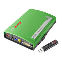
Bosch KTS 570 Original Instructions Manual (200 pages)
Module for controller diagnosis
Brand:
Bosch
| Category:
Control Unit
| Size: 11.43 MB
Table of Contents
4
Deutsch
1
Bluetooth Class
1
Bluetooth de Classe
1
Bluetooth Klasy
1
Bluetooth Luokka
1
Bluetooth Třída
1
蓝牙 - 等级
4
Table of Contents
5
1 Verwendete Symbolik
5
In der Dokumentation
5
Warnhinweise - Aufbau und Bedeutung
5
Symbole - Benennung und Bedeutung
5
Auf dem Produkt
5
2 Benutzerhinweise
6
Wichtige Hinweise zu Bluetooth
6
3 Gerätebeschreibung
6
Verwendung
7
Voraussetzungen
7
Hardware
7
Betriebssystem
7
Software
7
Lieferumfang
7
Sonderzubehör
8
Systemtester
8
Diagnoseleiste/Messleiste
8
Anschlussleiste
8
Statusanzeige LED a und LED B
9
Bluetooth
9
Bluetooth-USB-Adapter
9
Toshiba Bluetooth-Treiber
9
Microsoft Bluetooth-Treiber
9
Bedienung
9
Anschlussplan
10
Hinweise Steuergeräte-Diagnose
10
Hinweise zu Multimeter und Oszilloskop
10
Firmware-Update
11
4 Erstinbetriebnahme
11
Esi[Tronic] 2.0 Software-Installation
11
Bluetooth Einrichten
11
Anschluss
12
Modulkonfiguration (DDC)
12
Montage Befestigungshalter
13
Hinweise bei Störungen
13
Diagnosehardware Wurde nicht Gefunden
13
Keine Kommunikation mit dem Steuergerät
13
Bluetooth-Treiber-Initialisierung
14
5 Instandhaltung
14
Reinigung
14
Wartung
14
Ersatz- und Verschleißteile
15
6 Außerbetriebnahme
15
Vorübergehende Stilllegung
15
Ortswechsel
15
Entsorgung und Verschrottung
15
Entsorgung
15
7 Technische Daten
16
AC- und Effektivwert-Messung (CH1 und CH2) 1)
16
Widerstandsmessung (CH1)
16
Strommessung (CH1 und CH2)
16
Durchgangsprüfer (CH1)
16
Diodenmessung (CH1)
16
Netzteil
17
English
18
1 Symbols Used
18
In the Documentation
18
Warning Notices - Structure and Meaning
18
Symbols in this Documentation
18
On the Product
18
2 User Information
19
Important Information Regarding Bluetooth
19
3 Description of Unit
19
Application
20
Requirements
20
Hardware
20
Operating System
20
Software
20
Delivery Specification
20
Special Accessories
21
System Tester
21
Diagnosis Terminals/Measurement Terminals
21
Terminal Strip
21
Functions of Leds a and B
22
Bluetooth
22
Bluetooth USB Adapter
22
Toshiba Bluetooth Driver
22
Microsoft Bluetooth Driver
22
Operation
22
Connection Diagram
23
Notes Concerning Controller Diagnosis
23
Notes Concerning the Multimeter and Oscilloscope
23
Firmware Update
24
4 Initial Start-Up
24
Esi[Tronic] 2.0 Software Installation
24
Bluetooth Set-Up
24
Connection
25
Configuration (DDC)
25
Assembly Mount
26
Notes Concerning Faults
26
Diagnosis Hardware Has Not Been Found
26
No Communication with the Control Unit
26
Initializing Bluetooth Drivers
27
5 Maintenance
27
Cleaning
27
Spare and Wearing Parts
28
6 Decommissioning
28
Temporary Shutdown
28
Change of Location
28
Disposal and Scrapping
28
Disposal
28
7 Technical Data
29
AC and Effective Value Measurement (CH1 and CH2) *)
29
Resistance Measurement (CH1)
29
Current Measurement (CH1 and CH2)
29
Continuity Tester (CH1)
29
Diode Measurement (CH1)
29
Oscilloscope Specifications
30
Français
31
1 Symboles Utilisés
31
Dans la Documentation
31
Avertissements - Conception Et Signification
31
Symboles - Désignation Et Signification
31
Sur Le Produit
31
2 Consignes D'utilisation
32
Informations Importantes Sur Bluetooth
32
3 Description de L'appareil
32
Application
33
Conditions Préalables
33
Matériel
33
Système D'exploitation
33
Logiciel
33
Contenu de la Livraison
33
Accessoires Spéciaux
34
Testeur de Systèmes
34
Plaque de Diagnostic Et de Mesure
34
Barrette de Connexion
34
Fonctions des LED a Et B
35
Bluetooth
35
Adaptateur USB-Bluetooth
35
Pilote Bluetooth Toshiba
35
Pilote Bluetooth Microsoft
35
Utilisation
35
Schéma de Raccordement
36
Informations Concernant Le Diagnostic des Centrales de Commande
36
Informations Concernant Le Multimètre Et L'oscilloscope
36
Mise À Jour du Micrologiciel
37
4 Première Mise en Service
37
Installation du Logiciel Esi[Tronic]
37
Configuration de Bluetooth
37
Raccordement
38
Configuration (DDC)
38
Montage du Support de Fixation
39
Indication des Défauts
39
Matériel de Diagnostic Introuvable
39
Pas de Communication Avec la Centrale de Commande
39
Initialisation du Pilote Bluetooth
40
5 Maintenance
40
Nettoyage
40
Entretien
40
Pièces de Rechange Et D'usure
41
6 Mise Hors Service
41
Mise Hors Service Provisoire
41
Déplacement
41
Elimination Et Mise Au Rebut
41
Elimination
41
7 Caractéristiques Techniques
42
Mesure C.a. Et de la Valeur Efficace (CH1 Et CH2) *)
42
Mesure de la Résistance (CH1)
42
Mesure du Courant (CH1 Et CH2)
42
Testeur de Continuité (CH1)
42
Mesure des Diodes (CH1)
42
Spécifications de L'oscilloscope
43
Español
44
1 Símbolos Empleados
44
En la Documentación
44
Advertencias: Estructura y Significado
44
Símbolos en Esta Documentación
44
En el Producto
44
2 Indicaciones para el Usuario
45
Indicaciones Importantes sobre Bluetooth
45
3 Descripción del Aparato
45
Empleo
46
Condiciones Previas
46
Hardware
46
Sistema Operativo
46
Software
46
Volumen de Suministro
46
Accesorios Especiales
47
Comprobador del Sistema
47
Regleta de Diagnóstico /De Medición
47
Regleta de Conexión
47
Funciones de Los Leds a y B
48
Bluetooth
48
Adaptador Bluetooth-USB
48
Controlador de Bluetooth Toshiba
48
Controlador de Bluetooth Microsoft
48
Manejo
48
Esquema de Conexiones
49
Instrucciones Diagnóstico Aparatos de Control
49
Indicaciones sobre el Multímetro y el Osciloscopio
49
Actualización de Firmware
50
4 Primera Puesta en Servicio
50
Instalación de Software Esi[Tronic]
50
Configurar Bluetooth
50
Conexión
51
Configuración (DDC)
51
Montaje Soporte de Fijación
52
Indicaciones en Caso de Anomalías
52
No Se Encontró el Hardware de Diagnóstico
52
Sin Comunicación con la Unidad de Control
52
Inicialización del Controlador Bluetooth
53
5 Conservación
53
Limpieza
53
Mantenimiento
53
Piezas de Repuesto y Desgaste
54
6 Puesta Fuera de Servicio
54
Puesta Fuera de Servicio Pasajera
54
Cambio de Ubicación
54
Eliminación y Desguace
54
Eliminación
54
7 Datos Técnicos
55
Medición de C.A. y de Valor Efectivo
55
(CH1 y CH2)
55
Medición de Resistencia (CH1)
55
Medición de Corriente (CH1 y CH2)
55
Verificador de Paso (CH1)
55
Medición de Diodos (CH1)
56
Italiano
57
1 Simboli Utilizzati
57
Nella Documentazione
57
Indicazioni DI Avvertimento
57
Struttura E Significato
57
Simboli Nella Presente Documentazione
57
Sul Prodotto
58
Avvertenze Importanti Sul Bluetooth
58
3 Descrizione Dell'apparecchio
58
Uso
59
Requisiti
59
Hardware
59
Sistema Operativo
59
Software
59
Fornitura
59
Accessori Speciali
60
Tester DI Sistema
60
Pannello Porte DI Diagnosi/Misurazione
60
Pannello DI Collegamento
60
Funzioni Dei LED a E B
61
Bluetooth
61
Adattatore USB Bluetooth
61
Driver Bluetooth Toshiba
61
Driver Bluetooth Microsoft
61
Uso
61
Schema Dei Collegamenti
62
Avvertenze Per la Diagnosi Delle Centraline DI Comando
62
Avvertenze Sul Multimetro E Sull'oscilloscopio
62
Update Firmware
63
4 Prima Messa in Funzione
63
Installazione del Software Esi[Tronic]
63
Inserire Bluetooth
63
Collegamento
64
Configurazione (DDC)
64
Montaggio del Supporto DI Fissaggio
65
Avvertenze in Caso DI Guasto
65
L'hardware Diagnostico Non È Stato Trovato
65
Nessuna Comunicazione con la Centralina
65
Inizializzazione del Driver Bluetooth
66
5 Manutenzione
66
Pulizia
66
Ricambi E Parti Soggette a Usura
67
6 Messa Fuori Servizio
67
Messa Fuori Servizio Temporanea
67
Cambio DI Ubicazione
67
Smaltimento E Rottamazione
67
Smaltimento
67
7 Dati Tecnici
68
Misurazione C.a. E DI Valori Effettivi (CH1 E CH2) *)
68
Misurazione Della Resistenza (CH1)
68
Misurazione Della Corrente (CH1 E CH2)
68
Controllo DI Continuità (CH1)
68
Misurazione Diodi (CH1)
68
Alimentatore
69
Svenska
70
1 Använda Symboler
70
I Dokumentationen
70
Varningsanvisningar - Uppbyggnad Och Betydelse
70
Symboler - Benämning Och Betydelse
70
På Produkten
70
2 Användaranvisningar
71
Viktiga Anvisningar Om Bluetooth
71
3 Apparatbeskrivning
71
Användning
72
Förutsättningar
72
Hårdvara
72
Operativsystem
72
Programvara
72
Leveransomfattning
72
Specialtillbehör
73
Systemtester
73
Diagnoslist/Mätlist
73
Anslutningslist
73
Funktioner Hos Lysdioderna a Och B
74
Bluetooth
74
Bluetooth-USB-Adapter
74
Toshiba Bluetooth-Drivrutin
74
Microsoft Bluetooth-Drivrutin
74
Hantering
74
Anslutningsschema
75
Anvisningar Styrdonsdiagnos
75
Anvisningar Till Multimeter Och Oscilloskop
75
Firmware-Uppdatering
76
4 Idrifttagning För Första Gången
76
Esi[Tronic] 2.0 Program-Installation
76
Installera Bluetooth
76
Anslutning
77
Konfiguration (DDC)
77
Montering Infästningshållare
78
Anvisningar VID Störningar
78
Diagnosmaskinvaran Hittades Inte
78
Ingen Kommunikation Med Styrdonet
78
Aktivera Bluetooth-Drivrutin
79
KTS 530 / 540 / 570 (KTS 5 Series)
79
5 Underhåll
79
Rengöring
79
Service
79
Reserv- Och Slitdelar
80
6 Urdrifttagning
80
Temporärt Urdrifttagande
80
Byte Av Arbetsplats
80
Avfallshantering Och Skrotning
80
Avfallshantering
80
7 Tekniska Data
81
AC- Och Effektivvärdesmätning (CH1 Och CH2) *)
81
Resistansmätning (CH1)
81
StröMMätning (CH1 Och CH2)
81
Genomgångstestare (CH1)
81
Diodmätning (CH1)
81
Specifikation Oscilloskop
82
Dutch
83
1 Gebruikte Symbolen
83
In de Documentatie
83
Waarschuwingsaanwijzingen - Opbouw en Betekenis
83
Symbolen - Benaming en Betekenis
83
Op Het Product
83
2 Gebruikersinstructies
84
Belangrijke Instructies Bij Bluetooth
84
3 Beschrijving Van Het Apparaat
84
Toepassing
85
Voorwaarden
85
Hardware
85
Besturingssysteem
85
Software
85
Leveringsomvang
85
Speciale Toebehoren
86
Systeemtester
86
Diagnosestrook/Meetstrook
86
Aansluitstrook
86
Statusindicatie LED a en LED B
87
Bluetooth
87
Bluetooth USB-Adapter
87
Toshiba Bluetooth-Driver
87
Microsoft Bluetooth-Driver
87
De Bediening
87
Aansluitschema
88
Instructies Regeleenheid-Diagnose
88
Aanwijzingen Voor Multimeter en Oscilloscoop
88
Firmware-Update
89
4 Eerste Inbedrijfstelling
89
Software-Installatie Esi[Tronic]
89
Bluetooth Inrichten
89
Aansluiting
90
Moduleconfiguratie (DDC)
90
Montage Bevestigingshouder
91
Instructies Bij Storingen
91
Diagnosehardware Werd Niet Gevonden
91
Geen Communicatie Met de Regeleenheid
91
Bluetooth-Driver-Initialisering
92
5 Onderhoud
92
Reiniging
92
Reserve- en Slijtdelen
93
6 Buitenbedrijfstelling
93
Tijdelijke Buitenbedrijfstelling
93
Verplaatsing
93
Verwijderen en Tot Schroot Verwerken
93
Recycling
93
7 Technische Gegevens
94
AC- en Meting Effectieve Waarde (CH1 en CH2) *)
94
Weerstandsmeting (CH1)
94
Stroommeting (CH1 en CH2)
94
Doorgangsmeter (CH1)
94
Diodemeting (CH1)
94
Netvoeding
95
Português
96
1 Símbolos Utilizados
96
Na Documentação
96
Indicações de Aviso - Estrutura E Significado
96
Símbolos Nesta Documentação
96
No Produto
96
2 Instruções de Utilização
97
Notas Importantes sobre O Bluetooth
97
3 Descrição Do Aparelho
97
Utilização
98
Condições Prévias
98
Hardware
98
Sistema Operacional
98
Software
98
Âmbito Do Fornecimento
98
Acessórios Especiais
99
Aparelho de Teste Do Sistema
99
Painel de Diagnóstico/Painel de Medição
99
Painel de Conexão
99
Funções Dos Leds a E B
100
Bluetooth
100
Adaptador USB Bluetooth
100
Controlador Bluetooth Toshiba
100
Controlador Bluetooth Microsoft
100
Operação
100
Esquema de Ligações Elétricas
101
Notas Relativas Ao Diagnóstico de Unidades de Comando
101
Indicações Relativas Ao Multímetro E Ao Osciloscópio
101
Atualização Do Firmware
102
4 Primeira Colocação Em Funcionamento
102
Instalar Bluetooth
102
Conexão
103
Configuração (DDC)
103
Montagem Do Suporte de Fixação
104
Notas no Caso de Falhas
104
O Hardware de Diagnóstico Não Foi Encontrado
104
Não Há Comunicação Com a Unidade de Comando
104
Inicialização Do Controlador Bluetooth
105
5 Conservação
105
Limpeza
105
Manutenção
105
Peças de Reposição E de Desgaste
106
6 Colocação Fora de Serviço
106
Colocação Temporária Fora de Serviço
106
Mudança de Local
106
Eliminação E Transformação Em Sucata
106
Eliminação
106
7 Dados Técnicos
107
Medição AC E Valor Efetivo (CH1 E CH2)
107
Medição da Resistência (CH1)
107
Medição da Corrente (CH1 E CH2)
107
Teste de Passagem (CH1)
107
Medição Dos Díodos (CH1)
107
Especificação Do Osciloscópio
108
Suomi
109
1 Ohjeen Symbolit Ja Kuvakkeet
109
Ohjeistossa
109
Varoitustekstit - Rakenne Ja Merkitys
109
Tunnukset - Nimitykset Ja Merkitys
109
Tuotteessa
109
2 Ohjeita Käyttäjälle
110
Tärkeää Tietoa Bluetooth-Teknologiasta
110
3 Laiteseloste
110
Käyttö
111
Edellytykset
111
Laitteisto
111
Käyttöjärjestelmä
111
Ohjelmisto
111
Toimituksen Sisältö
111
Lisätarvikkeet
112
Järjestelmätesteri
112
Diagnoosi-/Mittaliitännät
112
Liitännät
112
LED a Ja LED B -Tilanäyttö
113
Bluetooth
113
Bluetooth-USB-Adapteri
113
Toshiba Bluetooth-Ajuri
113
Microsoft Bluetooth-Ajuri
113
Käyttö
113
Liitäntäkaavio
114
Ohjeita Ohjainlaitediagnoosiin
114
Yleismittarin Ja Oskilloskoopin Käyttö
114
Firmware-Päivitys
115
4 Ensimmäinen Käyttöönotto
115
Esi[Tronic] 2.0 -Ohjelmiston Installointi
115
Bluetooth-Yhteyden Luominen
115
Liitäntä
116
Moduulin Konfigurointi (DDC)
116
Kiinnitystelineen Ase Ntaminen
117
Ohjeita Häiriöiden Varalta
117
Diagnoosilaitteistoa Ei Löytynyt
117
Ei Kommunikaatiota Ohjainlaitteeseen
117
Bluetooth-Ajurin Alustus
118
5 Kunnossapito
118
Puhdistus
118
Huolto
118
Vara- Ja Kulutusosat
119
6 Laitteiden Alasajo
119
Väliaikainen Käytöstä Poisto
119
Muutto
119
Osien Hävittäminen Ja Romuttaminen
119
Jätemateriaalin Hävittäminen
119
7 Tekniset Tiedot
120
AC- Ja Teholliset Mittaukset (CH1 Ja CH2)
120
Vastusmittaus (CH1)
120
Virtamittaus (CH1 Ja CH2)
120
Yhteysmittaus (CH1)
120
Dioditesti (CH1)
120
Verkkolaite
Advertisement
Bosch KTS 570 Original Instructions Manual (170 pages)
Module for controller diagnosis
Brand:
Bosch
| Category:
Control Unit
| Size: 6.01 MB
Table of Contents
4
Deutsch
1
Bluetooth Class
1
Bluetooth Klasy
1
Bluetooth Luokka
1
Bluetooth Třída
1
蓝牙 - 等级
4
Table of Contents
5
1 Verwendete Symbolik
5
In der Dokumentation
5
Warnhinweise - Aufbau und Bedeutung
5
Symbole - Benennung und Bedeutung
5
Auf dem Produkt
5
2 Benutzerhinweise
6
Wichtige Hinweise zu Bluetooth
6
3 Gerätebeschreibung
6
Verwendung
6
Voraussetzungen
6
Hardware
6
Software
7
Lieferumfang
7
Sonderzubehör
7
Systemtester
7
Diagnoseleiste/Messleiste
7
Anschlussleiste
8
Statusanzeige LED a und LED B
8
Bedienung
8
Anschlussplan
9
Hinweise Steuergeräte-Diagnose
9
Hinweise zu Multimeter und Oszilloskop
9
Firmware-Update
10
Bluetooth-USB-Adapter
10
Microsoft Bluetooth-Treiber
10
4 Erstinbetriebnahme
10
Esi[Tronic] 2.0 Software-Installation
10
Bluetooth Einrichten
11
Anschluss über USB
11
Modulkonfiguration (DDC)
11
Montage Befestigungshalter
12
Hinweise bei Störungen
12
Diagnosehardware Wurde nicht Gefunden
12
Keine Kommunikation mit dem Steuergerät
12
5 Instandhaltung
12
Reinigung
12
Wartung
13
6 Außerbetriebnahme
13
Vorübergehende Stilllegung
13
Ortswechsel
13
Entsorgung und Verschrottung
13
7 Technische Daten
13
Allgemeine Daten
14
AC- und Effektivwert-Messung (CH1 und CH2)
14
Widerstandsmessung (CH1)
14
Strommessung (CH1 und CH2)
14
Durchgangsprüfer (CH1)
14
Diodenmessung (CH1)
14
Spezifikation Oszilloskop
15
English
16
1 Symbols Used
16
In the Documentation
16
Warning Notices - Structure and Meaning
16
Symbols in this Documentation
16
On the Product
16
2 User Information
17
Important Information Regarding Bluetooth
17
3 Device Description
17
Application
17
Prerequisites
17
Hardware
17
Software
18
Scope of Delivery
18
Special Accessories
18
System Tester
18
Diagnosis Terminals/Measurement Terminals
18
Connection Panel
19
LED a and LED B Status Display
19
Operation
19
Connection Diagram
20
Notes on Control Unit Diagnosis
20
Notes Concerning the Multimeter and Oscilloscope
20
Firmware Update
21
Bluetooth USB Adapter
21
Microsoft Bluetooth Driver
21
4 Initial Commissioning
21
Esi[Tronic] 2.0 Software Installation
21
Bluetooth Set-Up
22
Connecting Via USB
22
Module Configuration (DDC)
22
Fitting the Mounting Bracket
23
Troubleshooting
23
Diagnostic Hardware Not Found
23
No Communication with Control Unit
23
5 Maintenance
23
Cleaning
23
Spare and Wearing Parts
24
6 Decommissioning
24
Temporary Shutdown
24
Change of Location
24
Disposal and Scrapping
24
7 Technical Data
24
General Data
25
AC and Effective-Value Measurement (CH1 and CH2)
25
Resistance Measurement (CH1)
25
Current Measurement (CH1 and CH2)
25
Continuity Tester (CH1)
25
Diode Measurement (CH1)
25
Oscilloscope Specifications
37
Español
38
1 Símbolos Empleados
38
En la Documentación
38
Advertencias: Estructura y Significado
38
Símbolos en Esta Documentación
38
En el Producto
38
2 Indicaciones para el Usuario
39
Indicaciones Importantes sobre Bluetooth
39
3 Descripción del Producto
39
Empleo
39
Requisitos
39
Hardware
39
Software
40
Volumen de Suministro
40
Accesorios Especiales
40
Comprobador del Sistema
40
Regleta de Diagnóstico / de Medición
40
Regleta de Conexión
41
Indicación de Estado de Los LED a y B
41
Manejo
41
Esquema de Conexiones
42
Instrucciones para el Diagnóstico de Unidades de Mando
42
Indicaciones sobre el Multímetro Digital y el Osciloscopio
42
Actualización del Firmware
43
Adaptador Bluetooth USB
43
Controlador de Bluetooth Microsoft
43
4 Primera Puesta en Servicio
43
Instalación del Software del Producto
43
Esi[Tronic] 2.0
43
Configurar Bluetooth
44
Conexión Mediante USB
44
Configuración de Módulo (DDC)
44
Montaje del Soporte de Fijación
45
Instrucciones en Caso de Averías
45
No Se Encontró el Hardware de Diagnóstico
45
Sin Comunicación con la Unidad de Control
45
KTS 530 / 540 / 570 (KTS 5 Series)
45
5 Conservación
45
Limpieza
46
6 Puesta Fuera de Servicio
46
Puesta Fuera de Servicio Pasajera
46
Cambio de Ubicación
46
Eliminación y Desguace
46
7 Datos Técnicos
46
Datos Generales
47
Medición CA y de Valor Efectivo (CH1 y CH2)
47
Medición de Resistencia (CH1)
47
Medición de Corriente (CH1 y CH2)
47
Verificador de Paso (CH1)
47
Medición de Diodos (CH1)
47
Especificación Osciloscopio
48
Italiano
49
1 Simboli Utilizzati
49
Nella Documentazione
49
Indicazioni DI Avvertimento - Struttura E Significato
49
Simboli Nella Presente Documentazione
49
Sul Prodotto
49
2 Istruzioni Per L'utente
50
Avvertenze Importanti Sul Bluetooth
50
3 Descrizione del Dispositivo
50
Impiego
50
Requisiti Necessari
50
Hardware
50
Software
51
Fornitura
51
Accessori Speciali
51
Tester DI Sistema
51
Pannello DI Collegamento
52
Funzioni Dei LED a E B
52
Uso DI
52
Schema DI Collegamento
53
Avvertenze Per la Diagnosi Delle Centraline
53
Avvertenze Sul Multimetro E Sull'oscilloscopio
53
Aggiorn. Firmware
54
Adattatore USB Bluetooth
54
Driver Bluetooth Microsoft
54
4 Prima Messa in Esercizio
54
Installazione del Software Esi[Tronic]
54
Inserire Bluetooth
55
Collegamento Tramite USB
55
Configurazione Modulo (DDC)
55
Montaggio del Supporto DI Fissaggio
56
Avvertenze in Caso DI Anomalie
56
L'hardware Diagnostico Non È Stato Trovato
56
Nessuna Comunicazione con la Centralina
56
5 Manutenzione
56
Pulizia
56
Ricambi E Parti Soggette a Usura
57
6 Messa Fuori Servizio
57
Messa Fuori Servizio Temporanea
57
Cambio DI Ubicazione
57
Smaltimento E Rottamazione
57
7 Dati Tecnici
57
Dati Generali
58
Misurazione AC E Misurazione Valore Effettivo (CH1 E CH2)
58
Misurazione Della Resistenza (CH1)
58
Misurazione Della Corrente (CH1 E CH2)
58
Controllo DI Continuità (CH1)
58
Misurazione Diodi (CH1)
58
Specifiche Oscilloscopio
59
Svenska
60
1 Använda Symboler
60
I Dokumentationen
60
Varningsanvisningar - Uppbyggnad Och Betydelse
60
Symboler - Benämning Och Betydelse
60
På Produkten
60
2 Användaranvisningar
61
Viktiga Anvisningar Om Bluetooth
61
3 Enhetsbeskrivning
61
Användning
61
Förutsättningar
61
Hårdvara
61
Program
62
I Leveransen Ingår
62
Specialtillbehör
62
Systemtester
62
Diagnoslist/Mätlist
62
Anslutningslist
63
Statusindikering För LED a Och B
63
Användning
63
Anslutningsschema
64
Anvisningar Styrenhetsdiagnos
64
Anvisningar Till Multimeter Och Oscilloskop
64
Firmware-Uppdatering
65
Bluetooth-USB-Adapter
65
Microsoft Bluetooth-Drivrutin
65
4 Första Användningen
65
Esi[Tronic] 2.0 Program-Installation
65
Installera Bluetooth
65
Anslutning Via USB
66
Modulkonfiguration (DDC)
66
Montering Av Fästhållare
67
Anvisningar VID Fel
67
Diagnosmaskinvaran Hittades Inte
67
Ingen Kommunikation Med Styrenheten
67
5 Underhåll
67
Rengöring
67
Service
68
6 Urdrifttagning
68
Temporärt Urdrifttagande
68
Byte Av Arbetsplats
68
Avfallshantering Och Skrotning
68
7 Tekniska Data
68
Allmänna Data
69
AC- Och Effektivvärdesmätning (CH1 Och CH2)
69
Resistansmätning (CH1)
69
StröMMätning (CH1 Och CH2)
69
Genomgångstestare (CH1)
69
Diodmätning (CH1)
69
Specifikation För Oscilloskop
70
Dutch
71
1 Gebruikte Symbolen
71
In de Documentatie
71
Symbolen - Benaming en Betekenis
71
Op Het Product
71
2 Gebruikersinstructies
71
Belangrijke Opmerkingen
72
Belangrijke Instructies Bij Bluetooth
72
3 Apparaatbeschrijving
72
Toepassing
72
Voorwaarden
72
Hardware
72
Software
73
Leveringsomvang
73
Speciaal Toebehoren
73
Systeemtester
73
Diagnosestrook/Meetstrook
73
Aansluitstrook
74
Statusindicatie LED a en LED B
74
Bediening
74
Aansluitschema
75
Aanwijzingen Regeleenheiddiagnose
75
Aanwijzingen Voor Multimeter en Oscilloscoop
75
Firmware-Update
76
Bluetooth USB-Adapter
76
Microsoft Bluetooth-Driver
76
4 Eerste Inbedrijfstelling
76
Esi[Tronic] 2.0 Software-Installatie
76
Bluetooth Instellen
77
Aansluiting Via USB
77
Moduleconfiguratie (DDC)
77
Montage Bevestigingshouder
78
Instructies Bij Storingen
78
Diagnosehardware Werd Niet Gevonden
78
Geen Communicatie Met de Regeleenheid
78
5 Onderhoud
78
Reiniging
78
Reserve- en Slijtdelen
79
6 Buitenbedrijfstelling
79
Tijdelijke Buitenbedrijfstelling
79
Verplaatsing
79
Verwijderen en Tot Schroot Verwerken
79
7 Technische Gegevens
79
Algemene Gegevens
80
AC- en Meting Effectieve Waarde (CH1 en CH2)
80
Weerstandsmeting (CH1)
80
Stroommeting (CH1 en CH2)
80
Doorgangsmeter (CH1)
80
Diodemeting (CH1)
80
Specificatie Oscilloscoop
92
Suomi
93
1 Ohjeen Symbolit Ja Kuvakkeet
93
Ohjeistossa
93
Varoitustekstit - Rakenne Ja Merkitys
93
Tunnukset - Nimitykset Ja Merkitys
93
Tuotteessa
93
2 Ohjeita Käyttäjälle
94
Tärkeää Tietoa Bluetooth-Teknologiasta
94
3 Laitteen Kuvaus
94
Käyttökohteet
94
Edellytykset
94
Laitteisto
94
Ohjelmisto
95
Toimituksen Sisältö
95
Erikoisvarusteet
95
Järjestelmätesteri
95
Diagnoosinastat/Mittausnastat
95
Liitäntälista
96
Tilanäyttö LED a Ja LED B
96
Käyttö
96
Kytkentäkaavio
97
Ohjeet Ohjainlaitediagnoosi
97
Yleismittaria Ja Oskilloskooppia Koskevia Ohjeita
97
Firmware-Päivitys
98
Bluetooth USB-Adapteri
98
Microsoft Bluetooth-Ajuri
98
4 Ensimmäinen Käyttöönotto
98
Esi[Tronic] 2.0 -Ohjelmiston Asennus
98
Bluetooth-Installointi
99
Liitäntä Usb:n Kautta
99
Moduulin Konfigurointi (DDC)
99
Kiinnitystelineen Asentaminen
100
Ohjeita Häiriöiden Varalta
100
Diagnoosilaitteistoa Ei Löytynyt
100
Ei Kommunikaatiota Ohjainlaitteeseen
100
5 Kunnossapito
100
Puhdistus
100
Huolto
101
6 Laitteiden Alasajo
101
Väliaikainen Käytöstä Poisto
101
Muutto
101
Osien Hävittäminen Ja Romuttaminen
101
7 Tekniset Tiedot
101
Yleiset Tiedot
102
AC-Mittaus Ja Tehollisen Arvon Mittaus (CH1 Ja CH2)
102
Vastusmittaus (CH1)
102
Virtamittaus (CH1 Ja CH2)
102
Jatkuvuusmittari (CH1)
102
Dioditesti (CH1)
102
Oskilloskoopin Spesifikaatio
Bosch KTS 570 Operator Instructions Manual (11 pages)
Brand:
Bosch
| Category:
Barcode Reader
| Size: 1.02 MB
Table of Contents
1
Table of Contents
2
1 O P Er a Tor Instr U C Tions
2
IM Portant Notes
2
Safety Instructions
2
E Lectrom Ag Netic Com Patib Ility ( E MC)
2
Disposal
2
B Luetooth Lim Itations
3
2 D Escription of Unit
3
A Pplication
3
R Eq Uirements
3
H Ardw Are
3
Operating System
3
Softw Are
4
D E Liv E R Y S P E C Ifi C a Tio N
4
Special Accessories
4
System Tester
4
D Ia G N O S Is Te R M in a Ls / M E a S U Re M E N T
4
T E R M in a L S Tr Ip
5
Functions of L Eds a and B
5
Adapter Insert (IBOX 01)
5
Bluetooth
5
Bluetooth USB Adapter
5
Information Regarding Bluetooth Symbols
6
Operation
6
Connection Diagram
6
Notes Concerning Controller Diagnosis
7
N O Te S C O N C E R N in G Th E M U Ltim E Te R
7
A N D O S C Illo S C O P E
7
Firmware Update
7
Notes Concerning Faults
7
Diagnosis Hardware Has Not Been Found
7
No Communication with the Control Unit
8
Initializ Ing Bluetooth Drivers
9
3 I Nitial Start-Up
9
Assembly Mount
9
ESI[ Tronic] Software Installation
9
C O N N E C Tio N
9
C O N Fi G U R a Tio N ( D D C )
10
4 Maintenance
10
Cleaning
10
S Pare and W Earing Parts
10
5 Tec H Nic a L D a Ta
10
G Eneral D Ata
10
Interface Protocols
11
A C and Effectiv E V Alue Measurement
11
Resistance Measurement (CH1)
11
Current Measurement (CH1 and CH2)
11
Continuity Tester (CH1)
11
Diode Measurement (CH1)
11
O S C Illo S C O P E S P E C Ifi C a Tio N S
Advertisement
Share and save
Advertisement
Related Products
Bosch KTS 530
Bosch KTS 540
Bosch KTS 5a Series
Bosch KTS 560
Bosch KTS 590
Bosch KTS 515
Bosch KTS 5 Series
Bosch KTS 525
Bosch KTS 350
Bosch KTS 3a Series
Bosch Categories
Power Tool
Dishwasher
Washer
Drill
Security Camera
More Bosch Manuals
Login
Sign In
OR
Sign in with Facebook
Sign in with Google
Upload manual
Upload from disk
Upload from URL