Sign In
Upload
Manuals
Brands
Basler Manuals
Security Camera
racer
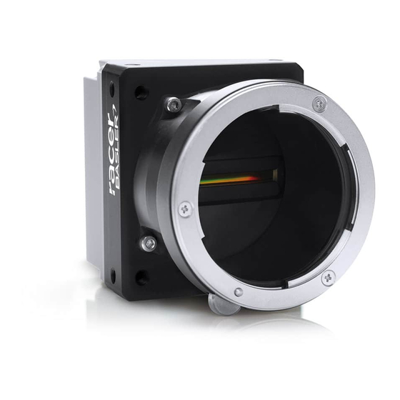
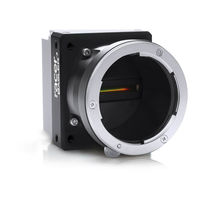
User Manuals: Basler racer Line Scan Cameras
Manuals and User Guides for Basler racer Line Scan Cameras. We have
3
Basler racer Line Scan Cameras manuals available for free PDF download: User Manual, Installation And Setup Manual, Manual
Basler racer User Manual (164 pages)
Camera Link Cameras
Brand:
Basler
| Category:
Digital Camera
| Size: 1 MB
Table of Contents
Table of Contents
5
1 Specifications, Requirements, and Precautions
9
Intended Use
9
Authorized Users
10
Models
10
General Specifications
11
Accessories
17
Spectral Response
18
Mechanical Specifications
19
Camera Dimensions and Mounting Points
19
Sensor Line Location
21
Lens Adapter Dimensions
22
Selecting the Optimum Lens Adapter
25
Attaching a Lens Adapter
25
Mechanical Stress Test Results
26
Software Licensing Information
27
LZ4 Licensing
27
Avoiding EMI and ESD Problems
28
Environmental Requirements
29
Temperature and Humidity
29
Heat Dissipation
29
Imaging Sensor over Temperature Condition
30
Precautions
31
2 Software and Hardware Installation
33
3 Camera Drivers and Tools for Changing Camera Parameters
34
Basler Pylon Camera Software Suite
34
Pylon Viewer
35
Pylon Sdks
35
Basler Binary Protocol Library
36
4 Camera Functional Description
37
5 Physical Interface
40
General Description of the Connections
40
Camera Connector Pin Assignments and Numbering
42
6-Pin Receptacle
42
26-Pin SDR Connectors
43
Cabling Requirements
46
Camera Power Cable and Grounding
46
Camera Link Cables
47
Camera Power
48
Supplying Power over Camera Link
48
Supplying Auxiliary Power Via the 6-Pin Connector
49
Power Intake Management
50
Camera Models with 2K and 4K Pixels
50
Camera Models with 6K, 8K, and 12K Pixels
50
LED Indicator
50
I/O in the Camera Link Interface
51
Inputs
51
Input Line Debouncers
51
Input Line Inverters
53
Function
54
Selecting an Input Line as a Source Signal for a Camera
54
Outputs
55
Minimum Output Pulse Width
56
Output Line Inverters
57
Selecting the Source Signal for an Output Line
57
Setting the State of a User Settable Output Line
59
Checking the State of the I/O Lines
60
Checking the State of a Single Line
60
Checking the State of All Lines
61
Checking the Line Logic of the I/O Lines
62
6 Acquisition Control
63
Line Start Triggering
63
Line Start with Triggermode = off
63
Line Start with Triggermode = on
65
Setting the Trigger Mode and Related Parameters
66
Using a Software Line Start Trigger Signal
68
Introduction
68
Setting the Parameters Related to Software Line Start Triggering and Applying a Software Trigger Signal
70
Using a Hardware Line Start Trigger Signal
72
Introduction
72
Exposure Modes
73
Setting the Parameters Related to Hardware Line Start Triggering and Applying a Hardware Trigger Signal
76
Overlapping Exposure with Sensor Readout
79
Guidelines for Overlapped Operation
81
Illegal Line Acquisition by Overtriggering
81
Regular Line Acquisition Avoiding Overtriggering
83
Acquisition Monitoring Tools
88
Exposure Active Signal
88
Acquisition Status
89
Line Trigger Wait Signal
90
Input Related Signals as Output Signals
94
Maximum Allowed Line Acquisition Rate
95
Increasing the Maximum Allowed Line Rate
97
Removing the Parameter Limits for the Exposure Overhead Parameter
99
Frequency Converter
101
7 Pixel Formats and Tap Geometries
104
Pixel Formats
104
Camera Link Tap Geometry
106
Setting the Tap Geometry
107
8 Features
108
Camera Link Pixel Clock Speed
108
Gain and Black Level
110
Gain
110
Analog Gain
110
Digital Gain
111
Using both Analog Gain and Digital Gain
112
Black Level
113
Remove Parameter Limits
114
Image Area of Interest (AOI)
115
Setting the Image AOI
115
Auto Functions
118
Common Characteristics
118
Auto Function Operating Modes
119
Auto Function AOI
120
Aois
121
Positioning of the Auto Function AOI Relative to the Image
121
Setting the Auto Function AOI
123
Gain Auto
124
Exposure Auto
125
Gray Value Adjustment Damping
127
Auto Function Profile
128
Luminance Lookup Table
129
Binning
132
Gamma Correction
133
Shading Correction
135
Offset Shading Correction
135
Gain Shading Correction
135
Default Shading Set File and User Shading Set File
136
Creating a "Usershading" File
136
Working with Shading Sets Using Basler Pylon
140
Working with Shading Sets Using Direct Register Access
141
Error Detection
142
LED Indicator
142
Error Codes
143
Test Images
145
Test Images in Detail
146
Device Information Parameters
147
User Defined Values
150
Configuration Sets
151
Saving Configuration Sets
152
Loading a Saved Set or the Default Set into the Active Set
153
Selecting the Default Startup Set
154
9 Troubleshooting and Support
155
Camera Reset
155
Tech Support Resources
156
Obtaining an RMA Number
156
Before Contacting Basler Technical Support
157
Revision History
159
Index
161
Advertisement
Basler racer Installation And Setup Manual (77 pages)
Brand:
Basler
| Category:
Security Camera
| Size: 0 MB
Table of Contents
Table of Contents
5
1 Introduction
7
Pylon Licensing Information
7
2 Precautions
8
Precautions Applicable to Specific Camera Series
8
Avoiding EMI and ESD Problems
8
3 Installing the Basler Pylon Camera Software Suite
9
System Requirements
9
Installation
9
4 Installing a Gige Camera
10
General Considerations
10
Installation Procedure
11
What Happens When Installing a Basler Gige Vision Network Driver
11
Software Installation
13
Adjusting the Installation
14
Configuring a Network Adapter Used with the Filter Driver
14
Disabling the Windows Firewall
17
Disabling the Windows Firewall Via the Traditional Control Panel
17
Disabling the Windows Firewall Via Advanced Security Settings
19
Disabling the Windows Firewall Via the Netsh Command Line Utility14
20
Hardware Installation
21
Precautions
21
Connectors of Gige Cameras
22
Installation
23
Network Recommendations
25
Recommended Network Adapters
25
If You Are Using Multiple Network Adapters in a Single Computer
26
Recommended Network Architectures
27
Camera and Network Adapter IP Configuration
30
Network Adapter IP Behavior
30
Changing a Network Adapter's IP Configuration
32
Setting an Adapter to Use a Fixed IP Address
32
Setting an Adapter to Use DHCP/ Auto IP (LLA)
35
Checking a Network Adapter's IP Address
37
Camera IP Behavior
38
Changing a Camera's IP Configuration
39
Modifying the Driver Installation
46
Changing the Driver Association for a Compatible Gige Network Adapter
46
Unbinding the Basler Filter Driver from a Network Adapter
47
5 Installing a Firewire Camera
48
General Considerations
48
Software and Hardware Installation
51
Precautions
51
Installing the Basler Pylon Camera Software Suite
51
Associating a Firewire Driver with Your Camera
52
6 Installing a Camera Link Camera
54
General Considerations
54
Frame Grabber Preparations
55
Location of the Serial Port File
55
Frame Grabber Camera Files
56
Hardware Installation
57
Precautions
57
Connectors of Camera Link Cameras
58
Installation
59
Software Installation
60
Configuring the Camera Link Serial Port
60
7 Next Steps
64
Acquiring Your First Images
64
Learning How to Configure and Optimize Your Camera
66
Additional Camera Settings
67
8 Uninstalling or Changing the Pylon Camera Software Suite
68
Revision History
69
Index
76
Basler racer Manual (46 pages)
CAMERA LINK INFORMATION FOR FRAME GRABBER DESIGNERS
Brand:
Basler
| Category:
Security Camera
| Size: 1 MB
Table of Contents
Table of Contents
5
1 Camera Link Implementation
7
Overview
7
SDR Connector Pin Assignments and Numbering
8
Electrical Implementation
11
Camera Link Input Signals
17
Serial to Camera
17
External Line Start Trigger (Exlstrig)
17
Camera Link Output Signals
18
Serial to Frame Grabber
18
Pixel Clock
18
Line Valid Bit
18
Data Valid Bit
19
CL Spare Bit
19
Pixel Data Bits
19
Tap Geometry - 8, 10, or 12 Bit Pixel Depth
20
1X2 Tap Geometry - 8, 10, or 12 Bit Pixel Depth
21
1X4 Tap Geometry - 8, 10, or 12 Bit Pixel Depth
22
1X8 Tap Geometry - 8 or 10 Bit Pixel Depth
24
1X10 Tap Geometry - 8 Bit Pixel Depth
27
2 Pixel Data Output
31
Data Depth
31
Pixel Clock Speed
31
Camera Link Tap Geometries
32
Factors Influencing the Timing of Pixel Data Transmission
32
Camera Link Pixel Clock
32
Delays
32
Tap Geometry
34
1X2 Tap Geometry
36
1X4 Tap Geometry
38
1X8 Tap Geometry
40
1X10 Tap Geometry
42
Revision History
45
Advertisement
Advertisement
Related Products
Basler runner
Basler Racer raL2048-48gm
Basler Racer raL4096-24gm
Basler Racer raL6144-16gm
Basler Racer raL8192-12gm
Basler Racer raL12288-8gm
Basler raL2048-80km
Basler raL4096-80km
Basler raL6144-80km
Basler raL8192-80km
Basler Categories
Relays
Digital Camera
Controller
Security Camera
Protection Device
More Basler Manuals
Login
Sign In
OR
Sign in with Facebook
Sign in with Google
Upload manual
Upload from disk
Upload from URL