Sign In
Upload
Manuals
Brands
Basler Manuals
Digital Camera
Racer raL2048-48gm
User Manuals: Basler Racer raL2048-48gm Scan Camera
Manuals and User Guides for Basler Racer raL2048-48gm Scan Camera. We have
2
Basler Racer raL2048-48gm Scan Camera manuals available for free PDF download: User Manual
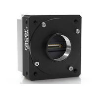
Basler Racer raL2048-48gm User Manual (238 pages)
GigE VISION CAMERAS
Brand:
Basler
| Category:
Digital Camera
| Size: 1 MB
Table of Contents
Table of Contents
5
1 Specifications, Requirements, and Precautions
11
Models
11
General Specifications
12
Spectral Response
16
Mechanical Specifications
17
Camera Dimensions and Mounting Points
17
Sensor Line Location
19
Lens Adapter Dimensions
20
Selecting the Optimum Lens Adapter
22
Attaching a Lens Adapter
22
Software Licensing Information
23
LWIP TCP/IP Licensing
23
LZ4 Licensing
24
Avoiding EMI and ESD Problems
25
Environmental Requirements
26
Temperature and Humidity
26
Heat Dissipation
26
Imaging Sensor over Temperature Condition
26
Precautions
27
2 Software and Hardware Installation
31
3 Tools for Changing Camera Parameters
33
The Pylon Viewer
33
The IP Configurator
33
The Pylon SDK
34
4 Basler Network Drivers and Parameters
35
The Basler Filter Driver
36
The Basler Performance Driver
37
Transport Layer Parameters
45
5 Network Related Camera Parameters and Managing Bandwidth
47
Network Related Parameters in the Camera
47
Managing Bandwidth When Multiple Cameras Share a Single Network Path
49
A Procedure for Managing Bandwidth
50
6 Camera Functional Description
55
7 Physical Interface
59
General Description of the Connections
59
Pin Numbering
60
Connector Pin Assignments
61
Pin Assignments for the 6-Pin Connector
61
Pin Assignments for the 12-Pin Connector
62
Pin Assignments for the RJ-45 Jack
62
Connector Types
63
6-Pin Connector
63
Jack
63
Cabling Requirements
64
Power Cable
64
I/O Cable
65
Ethernet Cables
65
Camera Power
66
Input and Output Lines
67
Input Lines
67
Electrical Characteristics
67
Input Line Debouncers
71
Input Line Inverters
72
Selecting an Input Line as a Source Signal for a Camera
72
Function
72
Output Lines
74
Electrical Characteristics
74
Input Related Signals as Output Signals
76
Minimum Output Pulse Width
77
Output Line Inverters
77
Selecting the Source Signal for an Output Line
78
Setting the State of User Settable Output Lines
80
Checking the State of the I/O Lines
81
Checking the Line Logic
82
I/O Line Response Times
83
Ethernet Gige Device Information
83
8 Acquisition Control
85
Defining a Frame
85
Controlling Acquisition
88
Acquisition Start and Stop Commands and the Acquisition Mode
88
Acquisition Start Triggering
90
Acquisition Start Trigger Mode = off
90
Acquisition Start Trigger Mode = on
90
Acquisition Frame Count
91
Setting the Acquisition Start Trigger Mode and
92
Setting the Acquisition Start Trigger Mode and Related Parameters
92
Frame Start Triggering
93
Frame Start Trigger Mode = off
93
Frame Start Trigger Mode = on
93
Setting the Frame Start Trigger Parameters
95
Frame Timeout
96
Line Start Triggering
97
Line Start Trigger Mode = off
97
Line Start Trigger Mode = on
98
Setting the Line Start Trigger Parameters
101
Exposure Time
102
Minimum and Maximum Exposure Times
102
Exposure Time Parameters
103
Use Case Descriptions and Diagrams
105
Overlapping Exposure with Sensor Readout
123
Guidelines for Overlapped Operation
124
Acquisition Monitoring Tools
132
Exposure Active Signal
133
Acquisition Status Indicator
134
Trigger Wait Signals
135
Acquisition Trigger Wait Signal
136
Frame Trigger Wait Signal
138
Line Trigger Wait Signal
140
Frame Transmission Time
144
Maximum Allowed Line Acquisition Rate
145
Removing the Parameter Limits for the Exposureoverhead Parameter
148
The Shaft Encoder Module
150
Frequency Converter
159
9 Pixel Data Formats
161
Setting the Pixel Data Format
161
Pixel Data Formats
162
Mono 8 Format
162
Mono 12 Format
163
Mono 12 Packed Format
165
YUV 4:2:2 Packed Format
167
YUV 4:2:2 (YUYV Packed) Format
169
Pixel Transmission Sequence
171
10 Standard Features
173
Gain and Black Level
173
Gain
173
Analog Gain
174
Digital Gain
174
Using both Analog Gain and Digital Gain
176
Black Level
176
Remove Parameter Limits
178
Image Area of Interest
179
Setting the Image AOI
179
Automatic Image AOI X Centering
180
Event Reporting
181
Luminance Lookup Table
184
Binning
187
Gamma Correction
188
Shading Correction
189
Offset Shading Correction
189
Gain Shading Correction
189
Default Shading Set File and User Shading Set File
190
Creating a "Usershading" File
190
Working with Shading Sets
193
Trigger Delay
194
Error Codes
195
Test Images
197
Test Images in Detail
198
Device Information Parameters
200
User Defined Values
202
Configuration Sets
203
Saving Configuration Sets
204
Loading a Saved Set or the Default Set into the Active Set
205
Selecting the Default Startup Set
205
11 Chunk Features
207
What Are Chunk Features
207
Making the "Chunk Mode" Active and Enabling the Extended Data Stamp
208
Frame Counter
210
Time Stamp
213
Trigger Counters
215
Encoder Counter
218
Input Line Status at Line Trigger
220
CRC Checksum
222
12 Troubleshooting and Support
225
Camera Reset
225
Tech Support Resources
226
Obtaining an RMA Number
226
Before Contacting Basler Technical Support
226
Revision History
229
Advertisement
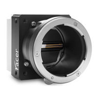
Basler Racer raL2048-48gm User Manual (234 pages)
GigE VISION CAMERAS
Brand:
Basler
| Category:
Digital Camera
| Size: 1 MB
Table of Contents
Table of Contents
5
1 Specifications, Requirements, and Precautions
9
Models
9
General Specifications
10
Spectral Response
14
Mechanical Specifications
15
Camera Dimensions and Mounting Points
15
Sensor Line Location
17
Lens Adapter Dimensions
18
Selecting the Optimum Lens Adapter
20
Attaching a Lens Adapter
20
Software Licensing Information
21
LWIP TCP/IP Licensing
21
LZ4 Licensing
22
Avoiding EMI and ESD Problems
23
Environmental Requirements
24
Temperature and Humidity
24
Heat Dissipation
24
Imaging Sensor over Temperature Condition
24
Precautions
25
2 Software and Hardware Installation
29
3 Tools for Changing Camera Parameters
31
The Pylon Viewer
31
The Pylon IP Configurator
31
The Pylon SDK
32
4 Basler Network Drivers and Parameters
33
The Basler Filter Driver
34
The Basler Performance Driver
35
Transport Layer Parameters
43
5 Network Related Camera Parameters and Managing Bandwidth
45
Network Related Parameters in the Camera
45
Managing Bandwidth When Multiple Cameras Share a Single Network Path
47
A Procedure for Managing Bandwidth
48
6 Camera Functional Description
53
7 Physical Interface
57
General Description of the Connections
57
Pin Numbering
58
Connector Pin Assignments
59
Pin Assignments for the 6-Pin Connector
59
Pin Assignments for the 12-Pin Connector
60
Pin Assignments for the RJ-45 Jack
60
Connector Types
61
6-Pin Connector
61
Jack
61
Cabling Requirements
62
Power Cable
62
I/O Cable
63
Ethernet Cables
63
Camera Power
64
Input and Output Lines
65
Input Lines
65
Electrical Characteristics
65
Input Line Debouncers
69
Input Line Inverters
70
Selecting an Input Line as a Source Signal for a Camera
70
Function
70
Output Lines
72
Electrical Characteristics
72
Input Related Signals as Output Signals
74
Minimum Output Pulse Width
75
Output Line Inverters
75
Selecting the Source Signal for an Output Line
76
Setting the State of User Settable Output Lines
78
Checking the State of the I/O Lines
79
Checking the Line Logic
80
I/O Line Response Times
81
Ethernet Gige Device Information
81
8 Acquisition Control
83
Defining a Frame
83
Controlling Acquisition
86
Acquisition Start and Stop Commands and the Acquisition Mode
86
Acquisition Start Triggering
88
Acquisition Start Trigger Mode = off
88
Acquisition Start Trigger Mode = on
88
Acquisition Frame Count
89
Setting the Acquisition Start Trigger Mode and
90
Setting the Acquisition Start Trigger Mode and Related Parameters
90
Frame Start Triggering
91
Frame Start Trigger Mode = off
91
Frame Start Trigger Mode = on
91
Setting the Frame Start Trigger Parameters
93
Frame Timeout
94
Line Start Triggering
95
Line Start Trigger Mode = off
95
Line Start Trigger Mode = on
96
Setting the Line Start Trigger Parameters
99
Exposure Time
100
Minimum and Maximum Exposure Times
100
Exposure Time Parameters
101
Use Case Descriptions and Diagrams
103
Overlapping Exposure with Sensor Readout
121
Guidelines for Overlapped Operation
122
Acquisition Monitoring Tools
129
Exposure Active Signal
130
Acquisition Status Indicator
131
Trigger Wait Signals
132
Acquisition Trigger Wait Signal
133
Frame Trigger Wait Signal
135
Line Trigger Wait Signal
137
Frame Transmission Time
141
Maximum Allowed Line Acquisition Rate
142
Removing the Parameter Limits for the Exposureoverhead Parameter
145
The Shaft Encoder Module
147
Frequency Converter
156
9 Pixel Data Formats
159
Setting the Pixel Data Format
159
Pixel Data Formats
160
Mono 8 Format
160
Mono 12 Format
161
Mono 12 Packed Format
163
YUV 4:2:2 Packed Format
165
YUV 4:2:2 (YUYV Packed) Format
167
Pixel Transmission Sequence
169
10 Standard Features
171
Gain and Black Level
171
Gain
171
Analog Gain
172
Digital Gain
172
Using both Analog Gain and Digital Gain
174
Black Level
174
Remove Parameter Limits
176
Image Area of Interest
177
Setting the Image AOI
177
Automatic Image AOI X Centering
178
Event Reporting
179
Luminance Lookup Table
182
Binning
185
Gamma Correction
186
Shading Correction
187
Offset Shading Correction
187
Gain Shading Correction
187
Default Shading Set File and User Shading Set File
188
Creating a "Usershading" File
188
Working with Shading Sets
191
Trigger Delay
192
Error Codes
193
Test Images
195
Test Images in Detail
196
Device Information Parameters
198
User Defined Values
200
Configuration Sets
201
Saving Configuration Sets
202
Loading a Saved Set or the Default Set into the Active Set
203
Selecting the Default Startup Set
203
11 Chunk Features
205
What Are Chunk Features
205
Making the "Chunk Mode" Active and Enabling the Extended Data Stamp
206
Frame Counter
208
Time Stamp
211
Trigger Counters
213
Encoder Counter
216
Input Line Status at Line Trigger
218
CRC Checksum
220
12 Troubleshooting and Support
223
Camera Reset
223
Tech Support Resources
224
Obtaining an RMA Number
224
Before Contacting Basler Technical Support
224
Revision History
227
Index
229
Advertisement
Related Products
Basler raL2048-80km
Basler Racer raL4096-24gm
Basler Racer raL6144-16gm
Basler Racer raL8192-12gm
Basler Racer raL12288-8gm
Basler raL4096-80km
Basler raL6144-80km
Basler raL8192-80km
Basler raL12288-66km
Basler racer
Basler Categories
Relays
Digital Camera
Controller
Security Camera
Protection Device
More Basler Manuals
Login
Sign In
OR
Sign in with Facebook
Sign in with Google
Upload manual
Upload from disk
Upload from URL