Sign In
Upload
Manuals
Brands
Allied Telesis Manuals
Network Hardware
AT-SBx81CFC960
Allied Telesis AT-SBx81CFC960 Manuals
Manuals and User Guides for Allied Telesis AT-SBx81CFC960. We have
2
Allied Telesis AT-SBx81CFC960 manuals available for free PDF download: Installation Manual
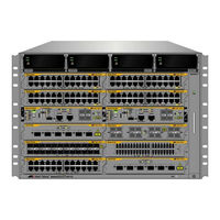
Allied Telesis AT-SBx81CFC960 Installation Manual (346 pages)
Brand:
Allied Telesis
| Category:
Switch
| Size: 6.8 MB
Table of Contents
Table of Contents
5
Preface
15
Structure of the Installation Guide
16
Safety Symbols Used in this Document
17
Contacting Allied Telesis
18
Section I: Hardware Overview
19
Chapter 1: Chassis and Power Supplies
21
AT-Sbx8112 Chassis
22
Figure 1: AT-Sbx8112 Chassis
22
Figure 2: Front View of the AT-Sbx8112 Chassis
23
Figure 3: Rear View of the AT-Sbx8112 Chassis
24
Figure 4: AT-Sbx8112 Chassis with Line Cards, Controller Cards, and Power Supplies
24
Slots for the Ethernet Line and Controller Cards
25
Figure 5: Ethernet Line and Controller Cards Slots
25
Power Supplies and Power Supply Slots
26
Figure 6: Power Supply Units
26
Figure 7: Power Supply Slots
27
Leds
28
Table 1. Leds on the AT-Sbxpwrsys1 and AT-Sbxpwrsys2 Power Supplies
29
Table 2. Leds on the AT-Sbxpwrsys1 DC System Power Supply
29
Table 3. Leds on the AT-Sbxpwrpoe1 Poe Power Supply
30
AT-Sbxfan12 Module
31
Led
31
Figure 8: AT-Sbxfan12 Module
31
Table 4. Power LED on the AT-Sbxfan12 Module
31
Power Supply Interfaces (Opto-Couplers)
32
Led
32
Figure 9: Power Supply Interfaces (Opto-Couplers)
32
Table 5. Power LED on the Power Supply Interface
33
Chapter 2: Ethernet Line Cards
35
Ethernet Line Cards
36
Figure 10: Ethernet Line Cards
36
Figure 11: Expansion Modules for the AT-Sbx81Xlem Line Card
37
Table 6. Transceiver Support
37
AT-Sbx81Gt24 Line Card
38
Leds
38
Figure 12: AT-Sbx81Gt24 Line Card
38
Figure 13: Port Leds on the AT-Sbx81Gt24 Line Card
39
Table 7. Port Leds on the AT-Sbx81Gt24 Line Card
39
AT-Sbx81Gt40 Line Card
40
Figure 14: AT-Sbx81Gt40 Line Card
40
Leds
41
Figure 15: Port Leds on an RJ Point 5 Cable Connector for the AT-Sbx81Gt40 Line Card
41
Figure 16: Port Leds on an RJ Point 5 Cable Connector for the AT-Sbx81Gt40 Line Card
41
Table 8. Port Leds on the AT-Sbx81Gt40 Line Card
42
AT-Sbx81Gp24 Poe Line Card
43
Figure 17: AT-Sbx81Gp24 Poe Line Card
43
Leds
44
Figure 18: Port Leds on the AT-Sbx81Gp24 Poe Line Card
44
Table 9. Port Leds on the AT-Sbx81Gp24 Poe Line Card
44
AT-Sbx81Gs24A SFP Line Card
46
Leds
46
Figure 19: AT-Sbx81Gs24A SFP Line Card
46
Figure 20: Port Leds on the AT-Sbx81Gs24A SFP Line Card
47
Table 10. Port Leds on the AT-Sbx81Gs24A SFP Line Card
47
AT-Sbx81Xs6 SFP+ Line Card
48
Leds
48
Figure 21: AT-Sbx81Xs6 Line Card
48
Figure 22: SFP+ Slot Leds on the AT-Sbx81Xs6 Line Card
48
Table 11. SFP+ Slot Leds on the AT-Sbx81Xs6 Line Card
49
AT-Sbx81Xs16 SFP+ Line Card
50
Leds
50
Figure 23: AT-Sbx81Xs16 Line Card
50
Figure 24: SFP+ Slot Leds on the AT-Sbx81Xs16 Line Card
51
Table 12. SFP+ Slot Leds on the AT-Sbx81Xs16 Line Card
51
AT-Sbx81Xlem SFP Line Card
52
Leds
52
Figure 25: AT-Sbx81Xlem SFP Line Card
52
Figure 26: Port Leds for the SFP Slots on the AT-Sbx81Xlem Line Card
53
Table 13. SFP Slot Leds on the AT-Sbx81Xlem Line Card
53
AT-Sbx81Xlem/Q2 Expansion Module
54
Led
54
Figure 27: AT-Sbx81Xlem/Q2 Expansion Module
54
Table 14. QSFP+ Slot Leds for the AT-Sbx81Xlem/Q2 Expansion Module
54
AT-Sbx81Xlem/Xs8 Expansion Module
56
Led
56
Figure 28: AT-Sbx81Xlem/Xs8 Expansion Module
56
Table 15. Slot Leds on the AT-Sbx81Xlem/Xs8 Module
56
10/100/1000Base-T Twisted Pair Ports
58
Connector Type
58
Speed
58
Duplex Mode
58
Maximum Distance
59
Cable Requirements
59
Table 16. Twisted Pair Cable for the AT-Sbx81Gt24 and AT-Sbx81Gt40 Line Cards
59
Automatic MDIX Detection
60
Port Pinouts
60
Table 17. Twisted Pair Cable for the AT-Sbx81Gp24 Line Card
60
Power over Ethernet on the Ports in the AT-Sbx81Gp24 Line Card
61
Powered Device Classes
61
Table 18. Ieee802.3Af and Ieee802.3At Powered Device Classes
61
Power Budget
62
Poe Wiring
62
Table 19. Maximum Number of Powered Devices
62
Chapter 3: AT-Sbx81Cfc960 Controller Fabric Card
65
Controller Fabric Cards for the AT-Sbx8112 Chassis
66
Figure 29: Controller Fabric Cards for the AT-Sbx8112 Chassis
66
Hardware Components on the AT-Sbx81Cfc960 Card
68
Figure 30: AT-Sbx81Cfc960 Controller Fabric Card
68
Table 20. Components on the AT-Sbx81Cfc960 Controller Fabric Card
68
Guidelines
70
Dual Controller Cards
72
SYS Status Leds
74
Table 21. SYS (System) Status Leds
74
Eco-Friendly Button
76
Sbx Linecard Status Leds
77
Table 22. Sbx Linecard Status Leds
77
SFP+ Slots
78
Table 23. Leds for the SFP+ Slots on the AT-Sbx81Cfc960 Controller Card
79
Console (RS-232) Port
80
Ethernet Management Port (NET MGMT)
81
Net Mgmt Led
81
Table 24. NET MGMT Port LED
82
USB Port
83
Reset Button
84
Alliedware Plus Software Releases for the Hardware Components
86
Table 25. Alliedware Plus Operating System Releases for the Hardware Components
86
Section II: Installing the Chassis
87
Chapter 4: Safety Precautions and Site Requirements
89
Reviewing Safety Precautions
90
Selecting a Site for the Switchblade X8112
94
Figure 31: 100 - 125 VAC 125 V NEMA 5-20 Plug and Receptacle
95
Installation Tools and Material
96
Chapter 5: Installing the Chassis in an Equipment Rack
97
Required Tools and Material
98
Preparing the Equipment Rack
99
Figure 32: Reserving Vertical Rack Space
100
Figure 33: Rack Mounting Hole Locations
101
Unpacking the AT-Sbx8112 Chassis
102
Figure 34: Components of the AT-Sbx8112 Chassis
102
Figure 35: Components of the AT-Sbx8112 Chassis (Continued)
103
Adjusting the Equipment Rack Brackets
104
Table 26. Front Panel to Rack Rail Dimensions
104
Figure 36: Rack Mounting Bracket Locations
105
Figure 37: Rack Bracket Locations for Reverse Position of Chassis
105
Installing the AT-Sbx8112 Chassis in the Equipment Rack
106
Figure 38: Lifting the AT-Sbx8112 Chassis into the Equipment Rack
107
Figure 39: Installing the Rack Mount Screws
108
Removing the Shipping Brace
109
Figure 40: Removing the Shipping Brace
109
Installing the Chassis Grounding Wire
110
Figure 41: Stripping the Grounding Wire
110
Figure 42: Removing the Grounding Lug
110
Figure 43: Attaching the Grounding Wire to the Grounding Lug
111
Figure 44: Installing the Grounding Lug and Wire
111
Chapter 6: Installing the Power Supplies
113
Protecting against Electrostatic Discharge (ESD)
114
Figure 45: ESD Socket and Wrist Strap
114
Installing AT-Sbxpwrsys1 or AT-Sbxpwrsys2 AC System Power Supplies
115
Figure 46: Power Supply Slots
116
Figure 47: Removing the Blank Slot Cover from Power Supply Slot C
116
Figure 48: Items Included with the AT-Sbxpwrsys1 or AT-Sbxpwrsys2 AC System Power Supply
117
Figure 49: Unlocking the Handle on the Power Supply
118
Figure 50: Inserting the AT-Sbxpwrsys1 or AT-Sbxpwrsys2 AC System Power Supply
118
Figure 51: Lowering the Handle on the AT-Sbxpwrsys1 or AT-Sbxpwrsys2 AC System Power Supply
119
Installing AT-Sbxpwrpoe1 Poe Power Supplies
121
Figure 52: Removing the Blank Slot Cover from Power Supply Slot a
122
Figure 53: Items Included with the AT-Sbxpwrpoe1 Power Supply Module
123
Figure 54: Unlocking the Handle on the AT-Sbxpwrpoe1 Power Supply
124
Figure 55: Inserting the AT-Sbxpwrpoe1 Power Supply
124
Figure 56: Locking the Handle on the AT-Sbxpwrpoe1 Power Supply
125
Installing AT-Sbxpwrsys1 DC System Power Supplies
126
Figure 57: Removing the Blank Slot Cover from Power Supply Slot C
127
Figure 58: Items Included with the AT-Sbxpwrsys1 DC Power Supply Module
128
Figure 59: On/Off Switch on the AT-Sbxpwrsys1 DC Power Supply
129
Figure 60: Loosening the Handle Locking Screw on the AT-Sbxpwrsys1 DC System Power Supply
129
Figure 61: Raising Handle on the AT-Sbxpwrsys1 DC Power Supply
130
Figure 62: Inserting the AT-Sbxpwrsys1 DC System Power Supply
130
Figure 63: Locking the Handle on the AT-Sbxpwrsys1 DC System Power Supply
131
Chapter 7: Installing the AT-Sbx81Cfc960 Control Card and Ethernet Line Cards
133
Guidelines to Handling the Controller and Line Cards
134
Figure 64: Aligning a Card in a Slot
135
Installing the AT-Sbx81Cfc960 Controller Fabric Card
136
Figure 65: Slots 5 and 6 for the AT-Sbx81Cfc960 Card
136
Figure 66: Items Included with the AT-Sbx81Cfc960 Controller Card
137
Figure 67: Removing the AT-Sbx81Cfc960 Controller Fabric Card from the Anti-Static Bag
137
Figure 68: Removing the Battery Insulator
138
Figure 69: Opening the Locking Handles on the AT-Sbx81Cfc960 Controller Fabric Card
138
Figure 70: Aligning the AT-Sbx81Cfc960 Card in the Chassis Slot
139
Figure 71: Closing the Locking Levers on the AT-Sbx81Cfc960 Controller Fabric Card
140
Figure 72: Tightening the Thumb Screws on the AT-Sbx81Cfc960 Card
141
Installing Expansion Modules in AT-Sbx81Xlem Ethernet Line Cards
142
Figure 73: Removing the AT-Sbx81Xlem Line Card from the Anti-Static Bag
143
Figure 74: Removing the Screws on the Blank Slot Cover on the AT-Sbx81Xlem Line Card
143
Figure 75: Removing the Blank Slot Cover from the AT-Sbx81Xlem Line Card
144
Figure 76: Retracting the Retaining Pin on the AT-Sbx81Xlem Line Card
145
Figure 77: Removing the Expansion Module from the Anti-Static Bag
145
Figure 78: Sliding the Expansion Module into the AT-Sbx81Xlem Line Card
146
Figure 79: Seating the Expansion Module on the Connector in the AT-Sbx81Xlem Line Card
147
Figure 80: Securing the Expansion Module
147
Figure 81: Releasing the Retaining Pin
148
Figure 82: Blank Slot Cover for the AT-Sbx81Xlem Line Card
148
Figure 83: Returning the Line Card to Its Anti-Static Bag
149
Installing the Ethernet Line Cards
150
Figure 84: Slots 1 to 4 and 7 to 12 for the Ethernet Line Cards
150
Figure 85: Removing a Blank Slot Cover
151
Figure 86: Removing an Ethernet Line Card from the Anti-Static Bag
151
Figure 87: Aligning an Ethernet Line Card in a Chassis Slot
152
Figure 88: Seating an Ethernet Line Card on the Backplane Connector
153
Figure 89: Tightening the Thumb Screws on an Ethernet Line Card
153
Installing Blank Slot Covers
155
Figure 90: Installing a Blank Slot Cover
155
Figure 91: Tightening the Thumbscrews on a Blank Slot Cover
155
Chapter 8: Cabling the Ethernet Line Cards
157
Cabling Guidelines for Twisted Pair Ports
158
Connecting Cables to the AT-Sbx81Gt40 Line Card
159
Figure 92: RJ Point 5 Cable Connector for AT-Sbx81Gt40 Line Card
159
Figure 93: Connecting Cables to Ports on the AT-Sbx81Gt40 Line Card
160
Guidelines to Installing SFP, SFP+, and QSFP+ Transceivers
161
Installing SFP or SFP+ Transceivers
162
Table 27. Transceiver Support
162
Figure 94: Removing the Dust Cover from a Transceiver Slot
163
Figure 95: Installing an SFP or SFP+ Transceiver
163
Figure 96: Installing an SFP+ Transceiver in the AT-Sbx81Xs6 Line Card
164
Figure 97: Removing the Dust Cover from a Transceiver
165
Figure 98: Verifying the Position of the Handle on the Transceiver in the AT-Sbx81Xs16 Line Card
165
Figure 99: Attaching a Fiber Optic Cable to a Transceiver in the AT-Sbx81Xs16 Line Card
166
Installing AT-SP10TW Direct Connect Cables
167
Figure 100: Removing the Dust Cover from an SFP+ Slot
167
Figure 101: Installing the AT-SP10TW Cable in the AT-Sbx81Xs16 Line Card or AT-Sbx81Xlem/Xs8 Expansion Module
168
Figure 102: Installing the AT-SP10TW Cable in the AT-Sbx81Xs6 Line Card
169
Installing AT-QSFPCU Cables
170
Figure 103: Removing the Dust Cover from a Slot on the AT-Sbx81Xlem/Q2 Expansion Module
170
Figure 104: Sliding the AT-QSFPCU Cable into the Slot
171
Installing AT-QSFPSR or AT-QSFPLR4 Transceivers
172
Chapter 9: Cabling the AT-Sbx81Cfc960 Controller Fabric Card
173
Cabling the NET MGMT Port
174
Installing SFP+ Transceivers
176
Figure 105: Removing a Dust Cover from an SFP+ Slot in the AT-Sbx81Cfc960 Controller Fabric Card
177
Figure 106: Handle on an SFP+ Transceiver
177
Figure 107: Installing an SFP+ Transceiver in the AT-Sbx81Cfc960 Controller Fabric Card
178
Figure 108: Removing the Dust Cover from an SFP+ Transceiver in the AT-Sbx81Cfc960 Controller Fabric Card
178
Figure 109: Positioning the Handle on the Transceiver
179
Figure 110: Attaching a Fiber Optic Cable to an SFP+ Transceiver in the AT-Sbx81Cfc960 Controller Fabric Card
180
Installing AT-SP10TW Cables
181
Figure 111: Installing an AT-SP10TW Cable in the AT-Sbx81Cfc960 Controller Fabric Card
182
Chapter 10: Powering on the Chassis
183
Verifying the Installation
184
Powering on AT-Sbxpwrsys1 or AT-Sbxpwrsys2 AC System Power Supplies
185
Figure 112: AC Sockets on the Rear Panel of the AT-Sbx8112 Chassis
186
Figure 113: Connecting the AC Power Cord for the AT-Sbxpwrsys1 or AT-Sbxpwrsys2 AC System Power
187
Figure 114: Securing the Power Cord for the AT-Sbxpwrsys1 or AT-Sbxpwrsys2 AC Power Supply to an
188
Powering on AT-Sbxpwrpoe1 Power Supplies
189
Figure 115: Connecting the AC Power Cord for the AT-Sbxpwrpoe1 Power Supply
189
Figure 116: Securing the Power Cord for the AT-Sbxpwrpoe1 Power Supply to an Anchor
190
Figure 117: Dress and Secure AC Power Cords
191
Powering on the AT-Sbxpwrsys1 DC System Power Supply
192
Figure 118: Components of the AT-Sbxpwrsys1 DC Power Supply
193
Choosing a Method for Attaching the Grounding Wire
194
Connecting the Grounding Wire with the Grounding Terminal
194
Figure 119: Grounding Wire Terminal
194
Figure 120: Stripping the Stranded Grounding Wire
194
Figure 121: Attaching the Stranded Grounding Wire to the Grounding Terminal
194
Figure 122: Removing the Nut and Washer from the Grounding Post
195
Figure 123: Installing the Grounding Wire
196
Connecting the Grounding Wire with Bare Wire
197
Figure 124: Stripping the Solid or Stranded Grounding Wire
197
Figure 125: Attaching the Bare Grounding Wire to the Grounding Post
197
Figure 126: Securing the Bare Grounding Wire to the Grounding Post
198
Choosing a Method for Attaching the Power Wires
199
Connecting the DC Power Wires with the Straight Terminals
199
Figure 127: Power Wire Terminals
199
Figure 128: Stripping the Power Wires
200
Figure 129: Attaching the Power Wires to the Straight Terminal Lugs
200
Figure 130: On/Off Switch on the AT-Sbxpwrsys1 DC Power Supply
201
Figure 131: Opening the Plastic Cover
202
Figure 132: Removing the Terminal Screws
203
Figure 133: Connecting the Positive (+) Power Wire with a Straight Terminal
204
Figure 134: Connecting the Negative (-) Power Wire with a Straight Terminal
205
Figure 135: Closing the Plastic Cover over the Terminal Connectors
206
Figure 136: Tightening the Handle Locking Screw
207
Connecting the DC Power Wires with the Right Angle Terminals
208
Figure 137: Stripping the Power Wires
208
Figure 138: Attaching the Power Wires to the Right Angle Terminals
208
Figure 139: Removing the Plastic Cover
209
Figure 140: Removing the Terminal Screws
210
Figure 141: Connecting the Positive (+) Power Wire with a Right Angle Terminal
211
Figure 142: Connecting the Negative (-) Power Wire with a Right Angle Terminal
212
Figure 143: Tightening the Handle Locking Screw
213
Connecting Bare DC Power Wires
214
Figure 144: Stripping Solid or Stranded DC Power Wires
214
Figure 145: Connecting the Positive Wire with Bare Wire
215
Figure 146: Connecting the Negative Lead Wire with Bare Wire
216
Monitoring the Initialization Process
218
Using the Leds to Monitor the Initialization Process
218
Using the Console Port to Monitor the Initialization Process
218
Figure 147: Initialization Messages for a Stand-Alone Switch
219
Figure 148: Initialization Messages for a Stand-Alone Switch (Continued)
220
Chapter 11: Verifying the Hardware Operations of the Chassis
221
Using the Leds to Verify the Chassis
222
Using Local Management to Verify the Chassis
224
Starting a Local Management Session
224
Figure 149: Connecting the Management Cable to the Console RS-232 Port
224
Entering the Alliedware Plus Operating System Commands
225
Figure 150: SHOW VERSION Command
225
Figure 151: SHOW CARD Command
226
Chapter 12: Troubleshooting
227
AT-Sbxpwrsys1, AT-Sbxpwrsys2, and AT-Sbxpwrpoe1 Power Supplies
228
AT-Sbxpwrsys1 DC System Power Supply
230
Ethernet Line Cards
232
Twisted Pair Ports
234
Power over Ethernet
236
Fiber Optic or Twisted Pair Transceivers
238
AT-Sbx81Cfc960 Controller Fabric Card
239
AT-Sbxfan12 Fan Module
240
Local (Console) Management Session
241
Power Supply Interfaces (Opto-Couplers)
242
Chapter 13: Replacing Modules
243
Replacing AT-Sbxpwrsys1, AT-Sbxpwrsys2, and AT-Sbxpwrpoe1 Power Supplies
244
Figure 152: Disconnecting the AC Power Cord from the AC Socket on the Back Panel
245
Figure 153: Lifting the Locking Handle on the Power Supply
246
Figure 154: Removing the Power Supply from the Chassis
247
Figure 155: Installing a Blank Power Supply Slot Cover
248
Figure 156: Lowering the Locking Handle on the Power Supply Slot Cover
249
Replacing the AT-Sbxpwrsys1 DC Power Supply
250
Figure 157: Loosening the Screw on the Locking Handle
250
Figure 158: Opening the Plastic Window over the Terminal Block
251
Figure 159: Removing the Negative Lead Wire
252
Figure 160: Removing the Positive Lead Wire from the Terminal Block
253
Figure 161: Reinstalling the Screws on the Positive and Negative Terminals
254
Figure 162: Closing the Plastic Cover
255
Figure 163: Removing the Grounding Wire
256
Figure 164: Reinstalling the Nut and Washer on the Grounding Post
257
Figure 165: Lifting the Locking Handle and Removing the Power Supply
258
Figure 166: Installing a Blank Power Supply Slot Cover
259
Figure 167: Lowering the Locking Handle on the Power Supply Slot Cover
260
Replacing Ethernet Line Cards
261
Replacing Expansion Modules in AT-Sbx81Xlem Line Cards
263
Figure 168: Removing the Screws from the Expansion Module
264
Figure 169: Retracting the Retaining Pin on the AT-Sbx81Xlem Line Card
264
Figure 170: Disconnecting the Expansion Module from the AT-Sbx81Xlem Line Card
265
Figure 171: Sliding the Expansion Module from the AT-Sbx81Xlem Line Card
266
Figure 172: Storing the Expansion Module in an Anti-Static Bag
266
Figure 173: Sliding the Blank Slot Cover into the AT-Sbx81Xlem Line Card
267
Figure 174: Securing the Blank Slot Cover
267
Figure 175: Releasing the Retaining Pin
268
Replacing the AT-Sbx81Cfc960 Controller Fabric Card
269
Replacing the AT-Sbxfan12 Fan Module
272
Removing the AT-Sbxfan12 Fan Module
272
Figure 176: Loosening the Screw on the AT-Sbxfan12 Fan Module
273
Figure 177: Loosening the AT-Sbxfan12 Fan Module from the Backplane Connector
274
Figure 178: Withdrawing the AT-Sbxfan12 Fan Module 51 MM (2 In.) from the Chassis
275
Installing a New AT-Sbxfan12 Fan Module
276
Figure 179: Removing the AT-Sbxfan12 Fan Module from the Chassis
276
Figure 180: Installing a New AT-Sbxfan12 Fan Module
277
Figure 181: Securing the AT-Sbxfan12 Fan Module on the Backplane Connector
278
Figure 182: Tightening the Screw on the AT-Sbxfan12 Fan Module
279
Chapter 14: Upgrading the Controller Fabric Card
281
Before You Begin
282
Upgrading the Controller Fabric Card
284
Section III: Building a Stack with Vcstack Plus
289
Chapter 15: Vcstack Plus Overview
291
Overview
292
Stack Trunk
293
Table 28. Direct Connect Cables
293
Cabling Configurations for the Trunk
295
One Controller Card Per Chassis
295
Figure 183: Cabling the SFP+ Slots When both Switches Have One Controller Card
295
Two Controller Cards Per Chassis
296
Figure 184: Cabling the SFP+ Slots When both Switches Have Two Controller Cards
296
Table 29. Cabling the SFP+ Slots When both Switches Have Two Controller Cards
297
Vcstack Plus Feature License
298
Optional Feature Licenses
299
Chassis ID Numbers
300
Figure 185: Chassis ID Number in the Numbering Format
300
Priority Numbers
301
Stacking Guidelines
303
Chapter 16: Building a Stack
305
Before You Begin
306
Displaying the Management Software Version Number
307
Figure 186: SHOW SYSTEM Command
307
Activating the Vcstack Plus Feature License
309
Figure 187: LICENSE Command
310
Figure 188: LICENSE Command Message with Two Controller Cards
310
Figure 189: LICENSE Command Message with One Controller Card
310
Enabling the Stacking Feature
311
Figure 190: STACK ENABLE Command Messages
311
Table 30. Descriptions of the STACK ENABLE Command Messages
311
Displaying the Feature Licenses
313
Figure 191: SHOW LICENSE BRIEF Command
313
Setting the ID Number
315
Figure 192: SHOW STACK Command
315
Figure 193: STACK RENUMBER Command Messages
316
Table 31. Descriptions of the STACK RENUMBER Command Messages
317
Figure 194: SHOW STACK Command
318
Setting the Priority Number
319
Powering off the Chassis
320
Configuring the Second Chassis
321
Cabling the SFP+ Slots on the Controller Cards
322
Powering on the Stack
323
Controlling the Selection of the Initial Active Master Controller Card
323
Powering on the Switches
324
Monitoring the Boot up Sequence
324
Figure 195: Initialization Messages for the Stack
325
Figure 196: Initialization Messages for the Stack (Continued)
326
Verifying the Stack
327
Figure 197: SHOW STACK Command
327
Installing Optional Feature Licenses
329
Troubleshooting the Stack
330
Appendix A: Technical Specifications
333
Physical Specifications
334
Table 32. Product Dimensions
334
Table 33. Product Weights
334
Environmental Specifications
336
Table 34. Environmental Specifications
336
Table 35. Acoustic Noise Test Components
336
Power Specifications
337
Table 36. AC Voltage and Frequency Requirements
337
Table 37. DC Voltage Requirements
337
Table 38. Typical Power Savings in Eco-Friendly Mode
337
Table 39. Maximum Power Consumption
338
Table 40. Maximum Power Efficiency
338
Table 41. Heat Dissipation
338
Table 42. Available Power over Ethernet with One Poe Power Supply
339
Table 43. Available Power over Ethernet with Two Poe Power Supplies
339
Table 44. Poe Mode on the AT-Sbx81Gp24 Poe Line Card
340
Safety and Electromagnetic Emissions Certifications
341
Table 45. Safety and Electromagnetic Emissions
341
Port Pinouts
342
Figure 198: Pin Numbers for RJ-45 and RJ Point 5 Ports (Front View)
342
Table 46. MDI Pin Signals (10Base-T or 100Base-TX)
342
Table 47. MDI-X Pin Signals (10Base-T or 100Base-TX)
342
Table 48. 1000Base-T Connector Pinouts
343
Fiber Optic Specifications of the AT-Stackop/0.3 and AT-Stackop/9.0 Transceivers
344
Table 49. Fiber Optic Port Specifications for the AT-Stackop/0.3 Module
344
Table 50. Fiber Optic Port Specifications for the AT-Stackop/9.0 Transceiver
344
Advertisement
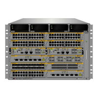
Allied Telesis AT-SBx81CFC960 Installation Manual (324 pages)
Brand:
Allied Telesis
| Category:
Network Hardware
| Size: 6.12 MB
Table of Contents
Installation Guide
1
Table of Contents
5
Preface
15
Structure of the Installation Guide
16
Safety Symbols Used in this Document
17
Contacting Allied Telesis
18
Section I: Hardware Overview
19
Chapter 1: Chassis and Power Supplies
21
AT-Sbx8112 Chassis
22
Figure 1: AT-Sbx8112 Chassis
22
Figure 2: Front View of the AT-Sbx8112 Chassis
23
Figure 3: Rear View of the AT-Sbx8112 Chassis
24
Figure 4: AT-Sbx8112 Chassis with Line Cards, Controller Cards, and Power Supplies
24
Slots for the Ethernet Line and Controller Cards
25
Figure 5: Ethernet Line and Controller Cards Slots
25
Power Supplies and Power Supply Slots
26
Figure 6: Power Supply Units
26
Figure 7: Power Supply Slots
27
Leds
28
Table 1. Leds on the AT-Sbxpwrsys1 and AT-Sbxpwrsys2 Power Supplies
29
Table 2. Leds on the AT-Sbxpwrsys1 DC System Power Supply
29
Table 3. Leds on the AT-Sbxpwrpoe1 Poe Power Supply
30
AT-Sbxfan12 Module
31
Led
31
Figure 8: AT-Sbxfan12 Module
31
Table 4. Power LED on the AT-Sbxfan12 Module
31
Power Supply Interfaces (Opto-Couplers)
32
Led
32
Figure 9: Power Supply Interfaces (Opto-Couplers)
32
Table 5. Power LED on the Power Supply Interface
33
Chapter 2: Ethernet Line Cards
35
Ethernet Line Cards
36
Figure 10: Ethernet Line Cards
36
AT-Sbx81Gt24 Line Card
37
Leds
37
Figure 11: AT-Sbx81Gt24 Line Card
37
Figure 12: Port Leds on the AT-Sbx81Gt24 Line Card
38
Table 6. Port Leds on the AT-Sbx81Gt24 Line Card
38
AT-Sbx81Gt40 Line Card
39
Figure 13: AT-Sbx81Gt40 Line Card
39
Figure 14: Port Leds on an RJ Point 5 Cable Connector for the AT-Sbx81Gt40 Line Card
40
Figure 15: Port Leds on an RJ Point 5 Cable Connector for the AT-Sbx81Gt40 Line Card
40
Leds
40
Table 7. Port Leds on the AT-Sbx81Gt40 Line Card
41
AT-Sbx81Gp24 Poe Line Card
42
Figure 16: AT-Sbx81Gp24 Poe Line Card
42
Figure 17: Port Leds on the AT-Sbx81Gp24 Poe Line Card
43
Leds
43
Table 8. Port Leds on the AT-Sbx81Gp24 Poe Line Card
43
AT-Sbx81Gs24A SFP Line Card
45
Leds
45
Figure 18: AT-Sbx81Gs24A SFP Line Card
45
Figure 19: Port Leds on the AT-Sbx81Gs24A SFP Line Card
46
Table 9. Port Leds on the AT-Sbx81Gs24A SFP Line Card
46
AT-Sbx81Xs6 SFP+ Line Card
47
Leds
47
Figure 20: AT-Sbx81Xs6 Line Card
47
Figure 21: SFP+ Slot Leds on the AT-Sbx81Xs6 Line Card
47
Table 10. SFP+ Slot Leds on the AT-Sbx81Xs6 Line Card
48
AT-Sbx81Xs16 SFP+ Line Card
49
Leds
49
Figure 22: AT-Sbx81Xs16 Line Card
49
Figure 23: SFP+ Slot Leds on the AT-Sbx81Xs16 Line Card
50
Table 11. SFP+ Slot Leds on the AT-Sbx81Xs16 Line Card
50
10/100/1000Base-T Twisted Pair Ports
51
Connector Type
51
Speed
51
Duplex Mode
51
Maximum Distance
51
Cable Requirements
52
Table 12. Twisted Pair Cable for the AT-Sbx81Gt24 and AT-Sbx81Gt40 Line Cards
52
Table 13. Twisted Pair Cable for the AT-Sbx81Gp24 Line Card
52
Automatic MDIX Detection
53
Port Pinouts
53
Power over Ethernet on the AT-Sbx81Gp24 Line Card
54
Powered Device Classes
54
Table 14. Ieee802.3Af and Ieee802.3At Powered Device Classes
54
Power Budget
55
Poe Wiring
55
Table 15. Maximum Number of Powered Devices
55
Chapter 3: AT-Sbx81Cfc960 Controller Fabric Card
57
Controller Fabric Cards for the AT-Sbx8112 Chassis
58
Figure 24: Controller Fabric Cards for the AT-Sbx8112 Chassis
58
Hardware Components on the AT-Sbx81Cfc960 Card
60
Figure 25: AT-Sbx81Cfc960 Controller Fabric Card
60
Table 16. Components on the AT-Sbx81Cfc960 Controller Fabric Card
60
Guidelines
62
Dual Controller Cards
64
SYS Status Leds
66
Table 17. SYS (System) Status Leds
66
Eco-Friendly Button
68
Sbx Linecard Status Leds
69
Table 18. Sbx Linecard Status Leds
69
SFP+ Slots
70
Table 19. Leds for the SFP+ Slots on the AT-Sbx81Cfc960 Controller Card
71
Console (RS-232) Port
72
Ethernet Management Port (NET MGMT)
73
Net Mgmt Led
73
Table 20. NET MGMT Port LED
74
USB Port
75
Reset Button
76
Alliedware Plus Software Releases for the Hardware Components
78
Table 21. Alliedware Plus Operating System Releases for the Hardware Components
78
Section II: Installing the Chassis
79
Chapter 4: Safety Precautions and Site Requirements
81
Reviewing Safety Precautions
82
Selecting a Site for the Switchblade X8112
86
Figure 26: 100 - 125 VAC 125 V NEMA 5-20 Plug and Receptacle
87
Installation Tools and Material
88
Chapter 5: Installing the Chassis in an Equipment Rack
89
Required Tools and Material
90
Preparing the Equipment Rack
91
Figure 27: Reserving Vertical Rack Space
92
Figure 28: Rack Mounting Hole Locations
93
Unpacking the AT-Sbx8112 Chassis
94
Figure 29: Components of the AT-Sbx8112 Chassis
94
Figure 30: Components of the AT-Sbx8112 Chassis (Continued)
95
Adjusting the Equipment Rack Brackets
96
Table 22. Front Panel to Rack Rail Dimensions
96
Figure 31: Rack Mounting Bracket Locations
97
Figure 32: Rack Bracket Locations for Reverse Position of Chassis
97
Installing the AT-Sbx8112 Chassis in the Equipment Rack
98
Figure 33: Lifting the AT-Sbx8112 Chassis into the Equipment Rack
99
Figure 34: Installing the Rack Mount Screws
100
Removing the Shipping Brace
101
Figure 35: Removing the Shipping Brace
101
Installing the Chassis Grounding Wire
102
Figure 36: Stripping the Grounding Wire
102
Figure 37: Removing the Grounding Lug
102
Figure 38: Attaching the Grounding Wire to the Grounding Lug
103
Figure 39: Installing the Grounding Lug and Wire
103
Chapter 6: Installing the Power Supplies
105
Protecting against Electrostatic Discharge (ESD)
106
Figure 40: ESD Socket and Wrist Strap
106
Installing AT-Sbxpwrsys1 or AT-Sbxpwrsys2 AC System Power Supplies
107
Figure 41: Power Supply Slots
108
Figure 42: Removing the Blank Slot Cover from Power Supply Slot C
108
Figure 43: Items Included with the AT-Sbxpwrsys1 or AT-Sbxpwrsys2 AC System Power Supply
109
Figure 44: Unlocking the Handle on the Power Supply
110
Figure 45: Inserting the AT-Sbxpwrsys1 or AT-Sbxpwrsys2 AC System Power Supply
110
Figure 46: Lowering the Handle on the AT-Sbxpwrsys1 or AT-Sbxpwrsys2 AC System Power Supply
111
Installing AT-Sbxpwrpoe1 Poe Power Supplies
113
Figure 47: Removing the Blank Slot Cover from Power Supply Slot a
114
Figure 48: Items Included with the AT-Sbxpwrpoe1 Power Supply Module
115
Figure 49: Unlocking the Handle on the AT-Sbxpwrpoe1 Power Supply
116
Figure 50: Inserting the AT-Sbxpwrpoe1 Power Supply
116
Figure 51: Locking the Handle on the AT-Sbxpwrpoe1 Power Supply
117
Installing AT-Sbxpwrsys1 DC System Power Supplies
118
Figure 52: Removing the Blank Slot Cover from Power Supply Slot C
119
Figure 53: Items Included with the AT-Sbxpwrsys1 DC Power Supply Module
120
Figure 54: On/Off Switch on the AT-Sbxpwrsys1 DC Power Supply
121
Figure 55: Loosening the Handle Locking Screw on the AT-Sbxpwrsys1 DC System Power Supply
121
Figure 56: Raising Handle on the AT-Sbxpwrsys1 DC Power Supply
122
Figure 57: Inserting the AT-Sbxpwrsys1 DC System Power Supply
122
Figure 58: Locking the Handle on the AT-Sbxpwrsys1 DC System Power Supply
123
Chapter 7: Installing the AT-Sbx81Cfc960 Control Card and Ethernet Line Cards
125
Guidelines to Handling the Controller and Line Cards
126
Figure 59: Aligning a Card in a Slot
127
Installing the AT-Sbx81Cfc960 Controller Fabric Card
128
Figure 60: Slots 5 and 6 for the AT-Sbx81Cfc960 Card
128
Figure 61: Items Included with the AT-Sbx81Cfc960 Controller Card
129
Figure 62: Removing the AT-Sbx81Cfc960 Controller Fabric Card from the Anti-Static Bag
129
Figure 63: Removing the Battery Insulator
130
Figure 64: Opening the Locking Handles on the AT-Sbx81Cfc960 Controller Fabric Card
130
Figure 65: Aligning the AT-Sbx81Cfc960 Card in the Chassis Slot
131
Figure 66: Closing the Locking Levers on the AT-Sbx81Cfc960 Controller Fabric Card
132
Figure 67: Tightening the Thumb Screws on the AT-Sbx81Cfc960 Card
133
Installing the Ethernet Line Cards
134
Figure 68: Slots 1 to 4 and 7 to 12 for the Ethernet Line Cards
134
Figure 69: Removing an Ethernet Line Card from the Anti-Static Bag
135
Figure 70: Aligning an Ethernet Line Card in a Chassis Slot
136
Figure 71: Seating an Ethernet Line Card on the Backplane Connector
137
Figure 72: Tightening the Thumb Screws on an Ethernet Line Card
137
Installing the Blank Slot Covers
139
Figure 73: Installing a Blank Slot Cover
139
Figure 74: Tightening the Thumbscrews on a Blank Slot Cover
139
Chapter 8: Installing the Transceivers and Cabling the Ports
141
Cabling Guidelines for the Twisted Pair Ports on the AT-Sbx81Gt24, AT-Sbx81Gt40, and AT-Sbx81Gp24 Line Cards
142
Connecting Cables to the AT-Sbx81Gt40 Line Card
143
Figure 75: RJ Point 5 Cable Connector for AT-Sbx81Gt40 Line Card
143
Figure 76: Connecting Cables to Ports on the AT-Sbx81Gt40 Line Card
144
Guidelines to Installing SFP and SFP+ Transceivers
145
Installing SFP Transceivers in the AT-Sbx81Gs24A Line Card
146
Figure 77: Removing the Dust Cover from an SFP Slot in the AT-Sbx81Gs24A Line Card
146
Figure 78: Handle on SFP Transceiver
146
Figure 79: Inserting the SFP Transceiver in the AT-Sbx81Gs24A Line Card
147
Figure 80: Removing the Dust Cover from the SFP Transceiver in the AT-Sbx81Gs24A Line Card
148
Figure 81: Verifying the Position of the Handle on an SFP Transceiver in the AT-Sbx81Gs24A Line Card
148
Figure 82: Attaching a Fiber Optic Cable to an SFP Transceiver in the AT-Sbx81Gs24A Line Card
149
Installing SFP+ Transceivers in the AT-Sbx81Xs6 Line Card
150
Figure 83: Removing the Dust Cover from an SFP+ Slot in the AT-Sbx81Xs6 Line Card
150
Figure 84: Handle on SFP+ Transceiver
151
Figure 85: Installing an SFP+ Transceiver in the AT-Sbx81Xs6 Line Card
151
Figure 86: Removing the Dust Cover from an SFP+ Transceiver in the AT-Sbx81Xs6 Line Card
152
Figure 87: Verifying the Position of the Handle on the SFP+ Transceiver in the AT-Sbx81Xs6 Line Card
152
Figure 88: Attaching a Fiber Optic Cable to an SFP+ Transceiver in the AT-Sbx81Xs6 Line Card
153
Installing AT-SP10TW Cables in the AT-Sbx81Xs6 Line Card
154
Figure 89: Removing the Dust Cover from an SFP+ Slot in the AT-Sbx81Xs6 Line Card
154
Figure 90: Installing the AT-SP10TW Cable in the AT-Sbx81Xs6 Line Card
155
Installing SFP+ Transceivers in the AT-Sbx81Xs16 Line Card
156
Figure 91: Removing the Dust Cover from a Transceiver Slot in the AT-Sbx81Xs16 Line Card
156
Figure 92: Installing a Transceiver in the AT-Sbx81Xs16 Line Card
157
Figure 93: Removing the Dust Cover from a Transceiver in the AT-Sbx81Xs16 Line Card
157
Figure 94: Verifying the Position of the Handle on the Transceiver in the AT-Sbx81Xs16 Line Card
158
Figure 95: Attaching a Fiber Optic Cable to a Transceiver in the AT-Sbx81Xs16 Line Card
159
Installing AT-SP10TW Cables in the AT-Sbx81Xs16 Line Card
160
Figure 96: Removing the Dust Cover from an SFP+ Slot on the AT-Sbx81Xs16 Line Card
160
Figure 97: Installing the AT-SP10TW Cable in the AT-Sbx81Xs16 Line Card
161
Cabling the NET MGMT Port on the AT-Sbx81Cfc960 Card
162
Installing SFP+ Transceivers in the AT-Sbx81Cfc960 Card
164
Figure 98: Removing a Dust Cover from an SFP+ Slot in the AT-Sbx81Cfc960 Controller Fabric Card
165
Figure 99: Handle on an SFP+ Transceiver
165
Figure 100: Installing an SFP+ Transceiver in the AT-Sbx81Cfc960 Controller Fabric Card
166
Figure 101: Removing the Dust Cover from an SFP+ Transceiver in the AT-Sbx81Cfc960 Controller Fabric Card
166
Figure 102: Positioning the Handle on the Transceiver
167
Figure 103: Attaching a Fiber Optic Cable to an SFP+ Transceiver in the AT-Sbx81Cfc960 Controller Fabric Card
168
Installing AT-SP10TW Cables in the AT-Sbx81Cfc960 Card
169
Figure 104: Installing an AT-SP10TW Cable in the AT-Sbx81Cfc960 Controller Fabric Card
170
Chapter 9: Powering on the Chassis
171
Verifying the Installation
172
Powering on AT-Sbxpwrsys1 or AT-Sbxpwrsys2 AC System Power Supplies
173
Figure 105: AC Sockets on the Rear Panel of the AT-Sbx8112 Chassis
174
Figure 106. Connecting the AC Power Cord for the AT-Sbxpwrsys1 or AT-Sbxpwrsys2 AC System Power Supply
175
Figure 107. Securing the Power Cord for the AT-Sbxpwrsys1 or AT- Sbxpwrsys2 AC Power Supply to an Anchor
176
Powering on AT-Sbxpwrpoe1 Power Supplies
177
Figure 108: Connecting the AC Power Cord for the AT-Sbxpwrpoe1 Power Supply
177
Figure 109: Securing the Power Cord for the AT-Sbxpwrpoe1 Power Supply to an Anchor
178
Figure 110: Dress and Secure AC Power Cords
179
Powering on the AT-Sbxpwrsys1 DC System Power Supply
180
Figure 111: Components of the AT-Sbxpwrsys1 DC Power Supply
181
Choosing a Method for Attaching the Grounding Wire
182
Connecting the Grounding Wire with the Grounding Terminal
182
Figure 112: Grounding Wire Terminal
182
Figure 113: Stripping the Stranded Grounding Wire
182
Figure 114: Attaching the Stranded Grounding Wire to the Grounding Terminal
182
Figure 115: Removing the Nut and Washer from the Grounding Post
183
Figure 116: Installing the Grounding Wire
184
Connecting the Grounding Wire with Bare Wire
185
Figure 117: Stripping the Solid or Stranded Grounding Wire
185
Figure 118: Attaching the Bare Grounding Wire to the Grounding Post
185
Figure 119: Securing the Bare Grounding Wire to the Grounding Post
186
Choosing a Method for Attaching the Power Wires
187
Connecting the DC Power Wires with the Straight Terminals
187
Figure 120: Power Wire Terminals
187
Figure 121: Stripping the Power Wires
188
Figure 122: Attaching the Power Wires to the Straight Terminal Lugs
188
Figure 123: On/Off Switch on the AT-Sbxpwrsys1 DC Power Supply
189
Figure 124: Opening the Plastic Cover
190
Figure 125: Removing the Terminal Screws
191
Figure 126: Connecting the Positive (+) Power Wire with a Straight Terminal
192
Figure 127: Connecting the Negative (-) Power Wire with a Straight Terminal
193
Figure 128: Closing the Plastic Cover over the Terminal Connectors
194
Figure 129: Tightening the Handle Locking Screw
195
Connecting the DC Power Wires with the Right Angle Terminals
196
Figure 130: Stripping the Power Wires
196
Figure 131: Attaching the Power Wires to the Right Angle Terminals
196
Figure 132: Removing the Plastic Cover
197
Figure 133: Removing the Terminal Screws
198
Figure 134: Connecting the Positive (+) Power Wire with a Right Angle Terminal
199
Figure 135: Connecting the Negative (-) Power Wire with a Right Angle Terminal
200
Figure 136: Tightening the Handle Locking Screw
201
Connecting Bare DC Power Wires
202
Figure 137: Stripping Solid or Stranded DC Power Wires
202
Figure 138: Connecting the Positive Wire with Bare Wire
203
Figure 139: Connecting the Negative Lead Wire with Bare Wire
204
Monitoring the Initialization Process
206
Using the Leds to Monitor the Initialization Process
206
Using the Console Port to Monitor the Initialization Process
206
Figure 140: Initialization Messages for a Stand-Alone Switch
207
Figure 141: Initialization Messages for a Stand-Alone Switch (Continued)
208
Chapter 10: Verifying the Hardware Operations of the Chassis
209
Using the Leds to Verify the Chassis
210
Using Local Management to Verify the Chassis
212
Starting a Local Management Session
212
Figure 142: Connecting the Management Cable to the Console RS-232 Port
212
Entering the Alliedware Plus Operating System Commands
213
Figure 143: SHOW VERSION Command
213
Figure 144: SHOW CARD Command
214
Chapter 11: Troubleshooting
215
AT-Sbxpwrsys1, AT-Sbxpwrsys2, and AT-Sbxpwrpoe1 Power Supplies
216
AT-Sbxpwrsys1 DC System Power Supply
218
Ethernet Line Cards
220
Twisted Pair Ports
222
Power over Ethernet
224
Fiber Optic or Twisted Pair Transceivers
226
AT-Sbx81Cfc960 Controller Fabric Card
227
AT-Sbxfan12 Fan Module
228
Local (Console) Management Session
229
Power Supply Interfaces (Opto-Couplers)
230
Chapter 12: Replacing Modules
231
Replacing AT-Sbxpwrsys1, AT-Sbxpwrsys2, and AT-Sbxpwrpoe1 Power Supplies
232
Figure 145: Disconnecting the AC Power Cord from the AC Socket on the Back Panel
233
Figure 146: Lifting the Locking Handle on the Power Supply
234
Figure 147: Removing the Power Supply from the Chassis
235
Figure 148: Installing a Blank Power Supply Slot Cover
236
Figure 149: Lowering the Locking Handle on the Power Supply Slot Cover
237
Replacing the AT-Sbxpwrsys1 DC Power Supply
238
Figure 150: Loosening the Screw on the Locking Handle
238
Figure 151: Opening the Plastic Window over the Terminal Block
239
Figure 152: Removing the Negative Lead Wire
240
Figure 153: Removing the Positive Lead Wire from the Terminal Block
241
Figure 154: Reinstalling the Screws on the Positive and Negative Terminals
242
Figure 155: Closing the Plastic Cover
243
Figure 156: Removing the Grounding Wire
244
Figure 157: Reinstalling the Nut and Washer on the Grounding Post
245
Figure 158: Lifting the Locking Handle and Removing the Power Supply
246
Figure 159: Installing a Blank Power Supply Slot Cover
247
Figure 160: Lowering the Locking Handle on the Power Supply Slot Cover
248
Replacing Ethernet Line Cards
249
Replacing the AT-Sbx81Cfc960 Controller Fabric Card
251
Replacing the AT-Sbxfan12 Fan Module
254
Removing the AT-Sbxfan12 Fan Module
254
Figure 161: Loosening the Screw on the AT-Sbxfan12 Fan Module
255
Figure 162: Loosening the AT-Sbxfan12 Fan Module from the Backplane Connector
256
Figure 163: Withdrawing the AT-Sbxfan12 Fan Module 51 MM (2 In.) from the Chassis
257
Installing a New AT-Sbxfan12 Fan Module
258
Figure 164: Removing the AT-Sbxfan12 Fan Module from the Chassis
258
Figure 165: Installing a New AT-Sbxfan12 Fan Module
259
Figure 166: Securing the AT-Sbxfan12 Fan Module on the Backplane Connector
260
Figure 167: Tightening the Screw on the AT-Sbxfan12 Fan Module
261
Chapter 13: Upgrading the Controller Fabric Card
263
Before You Begin
264
Upgrading the Controller Fabric Card
266
Section III: Building a Stack with Vcstack Plus
271
Chapter 14: Vcstack Plus Overview
273
Overview
274
Stack Trunk
275
Table 23. Direct Connect Cables
275
Cabling Configurations for the Trunk
277
One Controller Card Per Chassis
277
Figure 168: Cabling the SFP+ Slots When both Switches Have One Controller Card
277
Two Controller Cards Per Chassis
278
Figure 169: Cabling the SFP+ Slots When both Switches Have Two Controller Cards
278
Table 24. Cabling the SFP+ Slots When both Switches Have Two Controller Cards
279
Vcstack Plus Feature License
280
Optional Feature Licenses
281
Chassis ID Numbers
282
Figure 170: Chassis ID Number in the Numbering Format
282
Priority Numbers
283
Stacking Guidelines
285
Chapter 15: Building a Stack
287
Before You Begin
288
Displaying the Management Software Version Number
289
Figure 171: SHOW SYSTEM Command
289
Activating the Vcstack Plus Feature License
291
Figure 172: LICENSE Command
292
Figure 173: LICENSE Command Message with Two Controller Cards
292
Figure 174: LICENSE Command Message with One Controller Card
292
Enabling the Stacking Feature
293
Figure 175: STACK ENABLE Command Messages
293
Table 25. Descriptions of the STACK ENABLE Command Messages
293
Displaying the Feature Licenses
295
Figure 176: SHOW LICENSE BRIEF Command
295
Setting the ID Number
297
Figure 177: SHOW STACK Command
297
Figure 178: STACK RENUMBER Command Messages
298
Table 26. Descriptions of the STACK RENUMBER Command Messages
299
Figure 179: SHOW STACK Command
300
Setting the Priority Number
301
Powering off the Chassis
302
Configuring the Second Chassis
303
Cabling the SFP+ Slots on the Controller Cards
304
Powering on the Stack
305
Controlling the Selection of the Initial Active Master Controller Card
305
Powering on the Switches
306
Monitoring the Boot up Sequence
306
Figure 180: Initialization Messages for the Stack
307
Figure 181: Initialization Messages for the Stack (Continued)
308
Verifying the Stack
309
Figure 182: SHOW STACK Command
309
Installing Optional Feature Licenses
311
Troubleshooting the Stack
312
Appendix A: Technical Specifications
315
Physical Specifications
315
Table 27. Product Dimensions
315
Table 28. Product Weights
315
Environmental Specifications
317
Table 29. Environmental Specifications
317
Table 30. Acoustic Noise Test Components
317
Power Specifications
318
Table 31. AC Voltage and Frequency Requirements
318
Table 32. DC Voltage Requirements
318
Table 33. Typical Power Savings in Eco-Friendly Mode
318
Table 34. Maximum Power Consumption
318
Table 35. Maximum Power Efficiency
319
Table 36. Heat Dissipation
319
Table 37. Available Power over Ethernet with One Poe Power Supply
319
Safety and Electromagnetic Emissions Certifications
320
Table 38. Available Power over Ethernet with Two Poe Power Supplies
320
Table 39. Poe Mode on the AT-Sbx81Gp24 Poe Line Card
320
Table 40. Safety and Electromagnetic Emissions
320
Port Pinouts
321
Figure 183: Pin Numbers for RJ-45 and RJ Point 5 Ports (Front View)
321
Table 41. MDI Pin Signals (10Base-T or 100Base-TX)
321
Table 42. MDI-X Pin Signals (10Base-T or 100Base-TX)
321
Table 43. 1000Base-T Connector Pinouts
322
Fiber Optic Specifications of the AT-Stackop/0.3 and AT-Stackop/9.0 Transceivers
323
Table 44. Fiber Optic Port Specifications for the AT-Stackop/0.3 Module
323
Table 45. Fiber Optic Port Specifications for the AT-Stackop/9.0 Transceiver
323
Advertisement
Related Products
Allied Telesis AT-SBx8
Allied Telesis AT-SBx8106
Allied Telesis AT-SBx81GT24
Allied Telesis AT-SBx81GT40
Allied Telesis AT-SBx81GP24
Allied Telesis AT-SBx81GS24a
Allied Telesis AT-SBx81XS6
Allied Telesis AT-SBx81CFC400
Allied Telesis AT-SBxPWRSYS
Allied Telesis AT-SBxPWRSYS2
Allied Telesis Categories
Switch
Network Router
Media Converter
Network Hardware
Wireless Access Point
More Allied Telesis Manuals
Login
Sign In
OR
Sign in with Facebook
Sign in with Google
Upload manual
Upload from disk
Upload from URL