Sign In
Upload
Manuals
Brands
Agilent Technologies Manuals
Security Sensors
G7114A
Agilent Technologies G7114A Manuals
Manuals and User Guides for Agilent Technologies G7114A. We have
2
Agilent Technologies G7114A manuals available for free PDF download: User Manual, Quick Manual
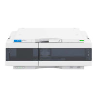
Agilent Technologies G7114A User Manual (222 pages)
Variable Wavelength Detectors
Brand:
Agilent Technologies
| Category:
Security Sensors
| Size: 3.96 MB
Table of Contents
Table of Contents
5
1 Introduction to the Variable Wavelength Detector
9
Introduction to the Detector
10
Product Description
11
Product Description G7114A
11
Product Description G7114B
12
Optical System Overview
13
Flow Cell
14
Entrance Slit Assembly
15
Lamp
15
Source Lens Assembly
15
Filter Assembly
16
Beam Splitter Assembly
17
Grating Assembly
17
Mirror Assemblies M1 and M2
17
Photo Diode ADC (Analog-To-Digital Converter)
17
Dual-Wavelength Mode
18
Photo Diodes Assemblies
17
Leak and Waste Handling
19
Leak Sensor
23
Waste Concept
23
Operating Principle
24
2 Site Requirements and Specifications
25
Site Requirements
26
Physical Specifications
29
Performance Specifications
30
Specifications
30
Specification Conditions
34
3 Using the Module
35
Magnets
36
Turn On/Off
37
Status Indicators
39
Instrument Configuration
40
Set up the Detector with Agilent Open Lab Chemstation
42
The Detector User Interface
43
Detector Control Settings
45
Method Parameter Settings
46
Scanning with the VWD
50
Agilent Local Control Modules
52
4 Preparing the Module
54
Leak and Waste Handling
55
Waste Concept
56
Setting up an Analysis
57
Before Using the System
57
Requirements and Conditions
59
Preparing the Detector
61
Preparing the HPLC System
61
Running the Sample and Verifying the Results
63
Solvent Information
64
5 Optimizing the Detector
69
Introduction
70
Match the Flow Cell to the Column
71
Set the Detector Parameters
74
Warm up of the Detector
75
6 Troubleshooting and Diagnostics
77
Available Tests Versus Interfaces
78
Agilent Lab Advisor Software
79
7 Error Information
80
What Are Error Messages
81
General Error Messages
82
Timeout
82
Shutdown
83
Remote Timeout
84
Lost CAN Partner
84
Leak
85
Leak Sensor Open
85
Leak Sensor Short
86
Compensation Sensor Open
86
Compensation Sensor Short
87
Fan Failed
87
Open Cover
88
ERI Messages
88
Detector Error Messages
89
UV Lamp: no Current
89
UV Lamp: no Voltage
90
Ignition Failed
90
No Heater Current
91
Wavelength Calibration Setting Failed
92
Wavelength Holmium Check Failed
93
Grating or Filter Motor Errors
94
Wavelength Test Failed
94
Cutoff Filter Doesn't Decrease the Light Intensity at 250 Nm
95
ADC Hardware Error
95
Illegal Temperature Value from Sensor on Main Board
96
Illegal Temperature Value from Sensor at Air Inlet
96
Heater at Fan Assembly Failed
97
Heater Power at Limit
97
Cover Violation
98
8 Test Functions
99
Introduction
100
Intensity Test
105
Intensity Test Evaluation
106
Intensity Test Failed
107
Cell Test
108
Cell Test Failed
109
Wavelength Verification-Calibration
110
When to Calibrate the Detector
110
ASTM Drift and Noise Test
112
Quick Noise Test
113
Dark Current Test
115
Dark Current Test Failed
116
Holmium Oxide Test
117
When to Do the Test
117
Interpreting the Results
118
Holmium Oxide Test Failed
119
D/A Converter (DAC) Test
120
D/A Converter Test Evaluation
122
Emfs - Early Maintenance Feature
123
Other Lab Advisor Functions
123
9 Maintenance
124
Introduction to Maintenance
125
Warnings and Cautions
126
Overview of Maintenance
128
Cleaning the Module
129
Remove and Install the Doors
130
Replace the Deuterium Lamp
132
Replace the Flow Cell / Cuvette Holder
135
Repair the Flow Cells
137
Using the Cuvette Holder
141
Correcting Leaks
143
Replace Leak Handling System Parts
145
Replace the Module Firmware
146
10 Parts and Materials for Maintenance
147
Overview of Maintenance Parts
148
Standard Flow Cell 10 MM / 14 Μl
150
Micro Flow Cell 3 MM / 2 Μl
152
Semi-Micro Flow Cell (Parts)
154
High Pressure Flow Cell (Parts)
156
Cuvette Holder (Parts)
157
Accessory Kit
158
11 Identifying Cables
159
Cable Overview
160
Analog Cables
162
Remote Cables
164
CAN Cable
168
Cables
169
USB Cables
170
12 Hardware Information
171
Firmware Description
172
Electrical Connections
175
Information on Instrument Serial Number
176
Interfaces
178
Rear View of the Module
176
Overview Interfaces
180
ERI (Enhanced Remote Interface)
183
USB (Universal Serial Bus)
185
Setting the 6-Bit Configuration Switch
186
Special Settings
188
Instrument Layout
190
Early Maintenance Feedback (EMF)
191
13 LAN Configuration
193
What You Have to Do First
194
TCP/IP Parameter Configuration
195
Configuration Switch
196
Initialization Mode Selection
197
Dynamic Host Configuration Protocol (DHCP)
199
General Information (DHCP)
199
Setup (DHCP)
200
Manual Configuration
202
With Telnet
203
14 Appendix
206
General
207
General Safety Information
207
Safety Standards
207
Before Applying Power
208
Ground the Instrument
208
Do Not Modify the Instrument
209
Do Not Operate in an Explosive Atmosphere
209
Do Not Remove the Instrument Cover
209
In Case of Damage
209
Solvents
210
Safety Symbols
211
Refrigerant
213
Waste Electrical and Electronic Equipment (WEEE) Directive
216
Radio Interference
217
Sound Emission
218
Solvent Information
219
Declaration of Conformity for HOX2 Filter
220
Agilent Technologies on Internet
221
Advertisement
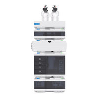
Agilent Technologies G7114A Quick Manual (82 pages)
Brand:
Agilent Technologies
| Category:
Laboratory Equipment
| Size: 2.4 MB
Table of Contents
Table of Contents
4
Introduction
5
Product Description
6
Features of the Agilent 1260 Infinity II Binary LC
7
System Components
8
Binary Pump G7112B
9
Multisampler G7167A
10
Vialsampler G7129A
11
Multicolumn Thermostat G7116A
12
Diode Array Detector HS G7117C
13
Diode Array Detector WR G7115A
14
Variable Wavelength Detector G7114A
15
Fluorescence Detector G7121A
16
Refractive Index Detector G7162A
17
Solutions
18
Walk-Up
18
Online SPE
18
1260 Infinity II Multimethod Solution
20
Optimizing the Stack Configuration
22
Agilent Infinitylab LC Flex Bench
22
One Stack Configuration
24
Two Stack Configuration
26
Leak and Waste Handling
28
Waste Guidance
32
Waste Concept
33
Configuration Settings
35
General Information on LAN Configuration
36
Instrument Configuration
37
Lab Advisor
39
3 Quick Start Guide
45
Best Practices
46
Prepare a Run
47
Check out the System
54
Checkout Method
54
Setup the Checkout Method
58
4 Parts and Consumables
65
Parts and Consumables Tool Kit
66
Infinitylab Quick Connect and Quick Turn Fittings
68
Infinitylab Quick Connect Fittings
68
Infinitylab Quick Connect Fitting Replacement Capillaries
69
Infinitylab Quick Turn Fitting
70
Capillaries for Use with the Infinitylab Quick Turn Fitting
71
5 Appendix
73
General
74
General Safety Information
74
Safety
74
Safety Standards
74
Before Applying Power
75
Ground the Instrument
75
Do Not Modify the Instrument
76
Do Not Operate in an Explosive Atmosphere
76
Do Not Remove the Instrument Cover
76
In Case of Damage
76
Solvents
77
Symbols
78
Appendix Safety
79
Agilent Technologies on Internet
80
Advertisement
Related Products
Agilent Technologies G7114B
Agilent Technologies G7117B
Agilent Technologies G7117A
Agilent Technologies G7117C
Agilent Technologies G1321A FLD
Agilent Technologies G3388A
Agilent Technologies G1314C VWD-SL
Agilent Technologies G8610 Series
Agilent Technologies G2621-64000
Agilent Technologies G1563A
Agilent Technologies Categories
Measuring Instruments
Laboratory Equipment
Test Equipment
Water Pump
Power Supply
More Agilent Technologies Manuals
Login
Sign In
OR
Sign in with Facebook
Sign in with Google
Upload manual
Upload from disk
Upload from URL