Sign In
Upload
Manuals
Brands
Aerotech Manuals
Controller
Automation1 XI4-4P1
Aerotech Automation1 XI4-4P1 Interface Manuals
Manuals and User Guides for Aerotech Automation1 XI4-4P1 Interface. We have
2
Aerotech Automation1 XI4-4P1 Interface manuals available for free PDF download: Hardware Manual
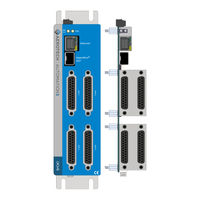
Aerotech Automation1 XI4-4P1 Hardware Manual (78 pages)
Transconductance Amplifier Controllers
Brand:
Aerotech
| Category:
Industrial Equipment
| Size: 7.58 MB
Table of Contents
Automation1 Ixi4 and XI4 Transconductance Amplifier Controllers
1
Table of Contents
3
List of Figures
5
List of Tables
6
EU Declaration of Conformity
9
Safety Procedures and Warnings
11
Handling and Storage
12
Installation Overview
13
Chapter 1: Ixi4/Xi4 Overview
15
Figure 1-1: Ixi4 Transconductance Amplifier Controller
15
Figure 1-2: XI4 Transconductance Amplifier Controller
16
Figure 1-3: Ixi4-OEM Transconductance Amplifier Controller
17
Figure 1-4: XI4-OEM Transconductance Amplifier Controller
18
Table 1-1: Feature Summary
19
Figure 1-5: Functional Diagram
20
Electrical Specifications
21
Table 1-2: Electrical Specifications
21
Mechanical Specifications
22
Mounting and Cooling
22
Table 1-3: Mounting Specifications
22
Dimensions
23
Figure 1-6: Dimensions [-2P1 (Standard 2-Axis)]
23
Figure 1-7: Dimensions [-4P1 (Standard 4-Axis)]
24
Figure 1-8: Dimensions [-2P2 (OEM 2-Axis)]
25
Figure 1-9: Dimensions [-4P2 (OEM 4-Axis)]
26
DIN Rail Mounting
27
Figure 1-10: Din Rail Clip Dimensions
27
Table 1-4: Mounting Parts
27
OEM Mounting
28
Table 1-5: OEM Mounting Parts
28
Environmental Specifications
29
Drive and Software Compatibility
29
Table 1-6: Environmental Specifications
29
Table 1-7: Drive and Software Compatibility
29
Chapter 2: Installation and Configuration
31
Input Power Connections
31
Control Supply Connector
31
Minimizing Noise for EMC/CE Compliance
31
Figure 2-1: Control Supply Connections
31
Table 2-1: Control Supply Connector Wiring Specifications
31
Table 2-2: Mating Connector Part Numbers for the Control Supply Connector
31
Axis Connector
32
Table 2-3: Axis Connector Pinout
32
Table 2-4: Mating Connector Part Numbers for the Axis Connector
32
Current Command Output Signals
33
Figure 2-2: Current Command Output Schematic
33
Table 2-5: Current Command Pins on the Axis Connector
33
Table 2-6: Current Command Signal Output Specifications
33
Stepper Clock and Stepper Direction Signals
34
Figure 2-3: Stepper Clock and Stepper Direction Timing
34
Table 2-7: Clock and Direction Pins on the Axis Connector
34
Table 2-8: Stepper Clock and Stepper Direction Signal Output Specifications
34
Table 2-9: Stepper Direction Signal Output Polarity
34
Figure 2-4: Stepper Clock and Stepper Direction Output Schematic
35
Hall-Effect Inputs
36
Figure 2-5: Hall-Effect Inputs Schematic
36
Table 2-10: Hall-Effect Feedback Pins on the Axis Connector
36
Brushless Motor Powered Motor and Feedback Phasing
37
Figure 2-6: Positive Motor Direction
37
Figure 2-7: Encoder and Hall Signal Diagnostics
37
Table 2-11: Hall Signal Diagnostics
37
End of Travel Limits
38
Figure 2-8: End of Travel Limit Input Connections
38
Figure 2-9: End of Travel Limit Input Schematic
38
Table 2-12: End of Travel Limit Pins on the Axis Connector
38
End of Travel Limit Phasing
39
Figure 2-10: End of Travel Limit Input Diagnostic Display
39
Amplifier Fault Inputs
40
Figure 2-11: Fault Input Schematic
40
Table 2-13: Amplifier Fault Input Specifications
40
Amplifier Enable Output
41
Figure 2-12: Amplifier Enable Output Schematic
41
Table 2-14: Amplifier Enable Connector Pin on the Axis Connector
41
Table 2-15: Amplifier Enable Output Specifications
41
Primary Encoder Inputs
42
Table 2-16: Multiplier Options
42
Table 2-17: Primary Encoder Input Pins on the Axis Connector
42
Square Wave Encoder (Primary)
43
Figure 2-13: Square Wave Encoder Schematic (Axis Connector)
43
Table 2-18: Square Wave Encoder Specifications
43
Absolute Encoder (Primary)
44
Figure 2-14: Absolute Encoder Schematic (Axis Connector)
44
Sine Wave Encoder (Primary)
45
Figure 2-15: Sine Wave Encoder Phasing Reference Diagram
45
Table 2-19: Sine Wave Encoder Specifications
45
Figure 2-16: Sine Wave Encoder Schematic (Axis Connector)
46
Encoder Phasing
47
Figure 2-17: Encoder Phasing Reference Diagram (Standard)
47
Figure 2-18: Position Feedback in the Diagnostic Display
47
Stepper Motor Phasing
48
Figure 2-19: Positive Motor Direction
48
Auxiliary Encoder Input
49
Square Wave Encoder (Auxiliary)
49
Figure 2-20: Square Wave Encoder Interface (Auxiliary)
49
Table 2-20: Auxiliary Encoder Pins on the Axis Connector
49
Table 2-21: Square Wave Encoder Specifications
49
Digital I/O Connector
50
Table 2-22: Digital I/O Connector Pinout
50
Table 2-23: Mating Connector Part Numbers for the Digital I/O Connector
50
Digital Outputs
51
Table 2-24: Digital Output Specifications
51
Table 2-25: Digital Output Pins on Digital I/O Connector
51
Figure 2-21: Digital Outputs Schematic
52
Figure 2-22: Digital Outputs Connected in Current Sourcing Mode
53
Figure 2-23: Digital Outputs Connected in Current Sinking Mode
53
Digital Inputs
54
Figure 2-24: Digital Inputs Schematic
54
Table 2-26: Digital Input Specifications
54
Table 2-27: Digital Input Pins on the Digital I/O Connector
54
Figure 2-25: Digital Inputs Connected to Current Sourcing (PNP) Devices
55
Figure 2-26: Digital Inputs Connected to Current Sinking (NPN) Devices
55
High-Speed User Input
56
Figure 2-27: High-Speed Input
56
Table 2-28: High-Speed Input Specifications
56
Table 2-29: High-Speed Input Pins on the Digital I/O Connector
56
Analog I/O and Laser Interface Connector
57
Table 2-30: Analog I/O and Laser Interface Connector Pinout
57
Table 2-31: Mating Connector Part Numbers for the Laser Interface Connector
57
Position Synchronized Output (PSO) Interface
58
Figure 2-28: PSO TTL Outputs Schematic
58
Table 2-32: PSO Specifications
58
Table 2-33: PSO External Sync Specifications
58
Table 2-34: PSO Output Pins on the Analog I/O and Laser Interface Connector
58
Figure 2-29: PSO External Sync Input Schematic
59
Analog Outputs
60
Figure 2-30: Analog Outputs Schematic
60
Table 2-35: Analog Output Specifications
60
Table 2-36: Analog Output Pins on the Analog I/O and Laser Interface Connector
60
Analog Inputs (Differential)
61
Figure 2-31: Analog Inputs Schematic
61
Table 2-37: Analog Input Specifications
61
Table 2-38: Analog Input Pins on the Analog I/O and Laser Interface Connector
61
Sync Port
62
Table 2-39: Sync-Related Functions
62
Table 2-40: Sync Port Cables
62
Hyperwire Interface
63
Table 2-41: Hyperwire Card Part Number
63
System Interconnection
64
Figure 2-32: Drive-Based Controller System Interconnection (Best Practice)
64
Figure 2-33: PC-Based Controller System Interconnection (Best Practice)
65
PC Configuration and Operation Information
66
Chapter 3: Cables and Accessories
67
Joystick Interface
67
Figure 3-1: Two Axis Joystick Interface
67
Handwheel Interface
68
Figure 3-2: Handwheel Interconnection to Axis Connector
68
Chapter 4: Maintenance
69
Preventative Maintenance
70
Advertisement
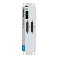
Aerotech Automation1 XI4-4P1 Hardware Manual (62 pages)
Stepper Controller
Brand:
Aerotech
| Category:
Controller
| Size: 3.4 MB
Table of Contents
Automation1 SI4 Stepper Controller
1
Table of Contents
3
List of Figures
4
List of Tables
5
EU Declaration of Conformity
7
Safety Procedures and Warnings
9
Installation Overview
11
Chapter 1: Introduction
13
Figure 1-1: SI4 Stepper Controller
13
Figure 1-2: SI4-OEM Stepper Controller
14
Table 1-1: Feature Summary
15
Figure 1-3: Functional Diagram
16
Electrical Specifications
17
Table 1-2: Electrical Specifications
17
Mechanical Specifications
18
Mounting and Cooling
18
Table 1-3: Mounting Specifications
18
Dimensions
19
Figure 1-4: Dimensions [-2P1 (Standard 2-Axis)]
19
Figure 1-5: Dimensions [-4P1 (Standard 4-Axis)]
20
Figure 1-6: Dimensions [-2P2 (OEM 2-Axis)]
21
Figure 1-7: Dimensions [-4P2 (OEM 4-Axis)]
22
DIN Rail Mounting
23
Figure 1-8: Din Rail Clip Dimensions
23
Table 1-4: Mounting Parts
23
OEM Mounting
24
Table 1-5: OEM Mounting Parts
24
Environmental Specifications
25
Table 1-6: Environmental Specifications
25
Drive and Software Compatibility
26
Table 1-7: Drive and Software Compatibility
26
Chapter 2: Installation and Configuration
27
Input Power Connections
28
Control Supply Connector
28
Figure 2-1: Control Supply Connections
28
Table 2-1: Control Supply Connector Wiring Specifications
28
Table 2-2: Mating Connector Part Numbers for the Control Supply Connector
28
Minimizing Noise for EMC/CE Compliance
29
Axis Connector
30
Table 2-3: Axis Connector Pinout
30
Table 2-4: Mating Connector Part Numbers for the Axis Connector
30
Figure 2-2: Stepper Clock and Stepper Direction Timing
31
Stepper Clock and Stepper Direction Signals
31
Table 2-5: Clock and Direction Pins on the Axis Connector
31
Table 2-6: Stepper Clock and Stepper Direction Signal Output Specifications
31
Table 2-7: Stepper Direction Signal Output Polarity
31
Figure 2-3: Stepper Clock and Stepper Direction Output Schematic
32
End of Travel Limits
33
Figure 2-4: End of Travel Limit Input Connections
33
Figure 2-5: End of Travel Limit Input Schematic
33
Table 2-8: End of Travel Limit Pins on the Axis Connector
33
End of Travel Limit Phasing
34
Figure 2-6: End of Travel Limit Input Diagnostic Display
34
Amplifier Fault Inputs
35
Figure 2-7: Fault Input Schematic
35
Table 2-9: Amplifier Fault Input Specifications
35
Amplifier Enable Output
36
Figure 2-8: Amplifier Enable Output Schematic
36
Table 2-10: Amplifier Enable Connector Pin on the Axis Connector
36
Table 2-11: Amplifier Enable Output Specifications
36
Primary Encoder Inputs
37
Table 2-12: Primary Encoder Input Pins on the Axis Connector
37
Figure 2-9: Square Wave Encoder Schematic (Axis Connector)
38
Square Wave Encoder
38
Table 2-13: Square Wave Encoder Specifications
38
Absolute Encoder
39
Figure 2-10: Absolute Encoder Schematic (Axis Connector)
39
Encoder Phasing
40
Figure 2-11: Encoder Phasing Reference Diagram (Standard)
40
Figure 2-12: Position Feedback in the Diagnostic Display
40
Figure 2-13: Positive Motor Direction
41
Stepper Motor Phasing
41
Digital I/O Connector
42
Table 2-14: Digital I/O Connector Pinout
42
Table 2-15: Mating Connector Part Numbers for the Digital I/O Connector
42
Digital Inputs
43
Figure 2-14: Digital Inputs Schematic
43
Table 2-16: Digital Input Specifications
43
Table 2-17: Digital Input Pins on the Digital I/O Connector
43
Figure 2-15: Digital Inputs Connected to Current Sourcing (PNP) Devices
44
Figure 2-16: Digital Inputs Connected to Current Sinking (NPN) Devices
44
Digital Outputs
45
Table 2-18: Digital Output Specifications
45
Table 2-19: Digital Output Pins on Digital I/O Connector
45
Figure 2-17: Digital Outputs Schematic
46
Figure 2-18: Digital Outputs Connected in Current Sourcing Mode
47
Figure 2-19: Digital Outputs Connected in Current Sinking Mode
47
Figure 2-20: High-Speed Input
48
High-Speed User Input
48
Table 2-20: High-Speed Input Specifications
48
Table 2-21: High-Speed Input Pins on the Digital I/O Connector
48
Figure 2-21: PSO TTL Outputs Schematic
49
Position Synchronized Output (PSO) Interface
49
Table 2-22: PSO Specifications
49
Table 2-23: PSO Output Pins on the Digital I/O Connector
49
Hyperwire Interface
50
Table 2-24: Hyperwire Card Part Number
50
Table 2-25: Hyperwire Cable Part Numbers
50
System Interconnection
51
Figure 2-22: System Interconnection Drawing (Best Practice)
51
PC Configuration and Operation Information
52
Chapter 3: Maintenance
53
Table 2-26: LED Description
53
Table 2-27: Troubleshooting
53
Preventative Maintenance
54
Table 2-28: Preventative Maintenance
54
Appendix A: Warranty and Field Service
55
Appendix B: Revision History
57
Index
59
Advertisement
Related Products
Aerotech AUTOMATION1-GL4
Aerotech Automation1 XL4s
Aerotech Automation1 SI4 Series
Aerotech Automation1 SI4-2P1
Aerotech Automation1 SI4-4P1
Aerotech Automation1 SI4-2P2
Aerotech Automation1 SI4-4P2
Aerotech Automation1 GI4 Galvo
Aerotech Automation1 XI4-2P1
Aerotech Automation1 XI4-2P2
Aerotech Categories
Industrial Equipment
DC Drives
Controller
Engine
Amplifier
More Aerotech Manuals
Login
Sign In
OR
Sign in with Facebook
Sign in with Google
Upload manual
Upload from disk
Upload from URL