Sign In
Upload
Manuals
Brands
Aerotech Manuals
Controller
Automation1 XL4s
Aerotech Automation1 XL4s Manuals
Manuals and User Guides for Aerotech Automation1 XL4s. We have
1
Aerotech Automation1 XL4s manual available for free PDF download: Hardware Manual
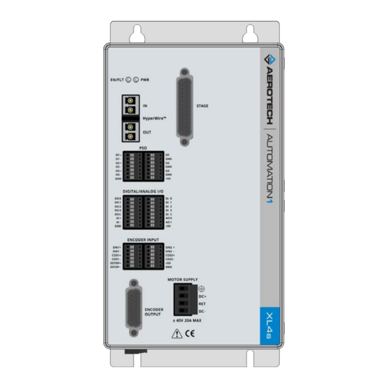
Aerotech Automation1 XL4s Hardware Manual (58 pages)
Brand:
Aerotech
| Category:
Controller
| Size: 1 MB
Table of Contents
Xl4S HARDWARE MANUAL
1
Table of Contents
3
List of Figures
4
List of Tables
5
EU Declaration of Conformity
7
Agency Approvals
9
Safety Procedures and Warnings
11
Quick Installation Guide
13
Chapter 1: Introduction
15
Figure 1-1: Xl4S High Performance Linear Amplifier
15
Table 1-1: Feature Summary
15
Figure 1-2: Functional Diagram
16
Electrical Specifications
17
Table 1-2: Electrical Specifications
17
Mechanical Specifications
18
Mounting and Cooling
18
Table 1-3: Mounting Specifications
18
Dimensions
19
Figure 1-3: Dimensions
19
Environmental Specifications
20
Table 1-4: Environmental Specifications
20
Drive and Software Compatibility
21
Table 1-5: Drive and Software Compatibility
21
Chapter 2: Installation and Configuration
23
Input Power Connections
23
Control Supply Connector
23
Figure 2-1: Control Supply Connections
23
Table 2-1: Control Supply Connector Wiring Specifications
23
Table 2-2: Mating Connector Part Numbers for the Control Supply Connector
23
Motor Supply Connector
24
Figure 2-2: Motor Supply Connections
24
Table 2-3: Motor Supply Wiring Specifications
24
Table 2-4: Mating Connector Part Numbers for the Motor Supply Connector
24
External Power Supply Options
25
Figure 2-3: Control and Motor Power Wiring Using a TM3 Transformer
25
Figure 2-4: Third-Party Power Supply Connection
26
Minimizing Conducted, Radiated, and System Noise for EMC/CE Compliance
27
Hyperwire Interface
28
Table 2-5: Hyperwire Card Part Number
28
Table 2-6: Hyperwire Cable Part Numbers
28
Position Synchronized Output Connector
29
Table 2-7: PSO Connector a Pinout
29
Table 2-8: PSO Connector B Pinout
29
Table 2-9: Mating Connector Part Numbers for the PSO Connectors
29
Table 2-10: PSO Specifications
29
Encoder Output Connector
30
Figure 2-5: Encoder Outputs Schematic
30
Table 2-11: Encoder Output Connector Pinout
30
Table 2-12: Mating Connector Part Numbers for the Encoder Output Connector
30
Figure 2-6: PSO External Sync Input Schematic
31
Table 2-13: PSO External Sync Specifications
31
Stage Motor and Feedback Connector
32
Table 2-14: Stage Motor and Feedback Connector Pinout
32
Table 2-15: Mating Connector Part Numbers for the Stage Motor and Feedback Connector
32
Analog Encoder Inputs
33
Table 2-16: Analog Encoder Input Specifications
33
Digital and Analog I/O Connectors
34
Table 2-17: Digital and Analog I/O Connector a Pinout
34
Table 2-18: Digital and Analog I/O Connector B Pinout
34
Table 2-19: Mating Connector Part Numbers for the Digital / Analog I/O Connectors
34
Digital Outputs
35
Table 2-20: Digital Output Specifications
35
Table 2-21: Digital Output Pins on the Digital/Analog I/O a Connector
35
Figure 2-7: Digital Outputs Connected in Current Sourcing Mode
36
Figure 2-8: Digital Outputs Connected in Current Sinking Mode
36
Digital Inputs
37
Figure 2-10: Digital Inputs Connected to Current Sourcing Devices
37
Figure 2-9: Digital Inputs Connected to Current Sinking Devices
37
Table 2-22: Digital Input Specifications
37
Table 2-23: Digital Input Pins on the Digital/Analog I/O B Connector
37
Analog Outputs
38
Figure 2-11: Analog Outputs Schematic
38
Table 2-24: Analog Output Specifications
38
Table 2-25: Analog Output Pins on the Digital / Analog I/O B Connector
38
Analog Inputs (Differential)
39
Figure 2-12: Analog Inputs Schematic
39
Table 2-26: Analog Input Specifications
39
Table 2-27: Analog Input Pins on the Digital / Analog I/O B Connector
39
Encoder Input Connectors
40
Table 2-28: Encoder Input Connector Specifications
40
Table 2-29: Encoder Input Connector a Pinout
40
Table 2-30: Encoder Input Connector B Pinout
40
Table 2-31: Mating Connector Part Numbers for the Encoder Input Connector
40
Figure 2-13: Encoder Input Connector Encoder Connections
41
Emergency Stop Sense Input
42
Figure 2-14: ESTOP Sense Input Schematic
42
Table 2-32: ESTOP Pins on the Encoder Input Connector
42
Table 2-33: Electrical Noise Suppression Devices
42
Laser Output Polarity Switch
43
Figure 2-15: Laser Output Polarity Switch Location
43
Sync Port
44
Table 2-34: Sync-Related Commands
44
Table 2-35: Sync Port Cables
44
PC Configuration and Operation Information
45
Chapter 3: Maintenance
47
Preventative Maintenance
47
Table 3-1: Preventative Maintenance
47
Board Assembly
48
Figure 3-1: Control Board Assembly
48
Table 3-2: Control Board Fuse Specifications
48
Figure 3-2: Power Board Assembly
49
Table 3-3: Power Board Fuse Specifications
49
Appendix A: Warranty and Field Service
51
Appendix B: Revision History
53
Index
55
Advertisement
Advertisement
Related Products
Aerotech AUTOMATION1-GL4
Aerotech Automation1 SI4 Series
Aerotech Automation1 SI4-2P1
Aerotech Automation1 SI4-4P1
Aerotech Automation1 SI4-2P2
Aerotech Automation1 SI4-4P2
Aerotech Automation1 GI4 Galvo
Aerotech Automation1 XI4-2P1
Aerotech Automation1 XI4-4P1
Aerotech Automation1 XI4-2P2
Aerotech Categories
Industrial Equipment
DC Drives
Controller
Engine
Amplifier
More Aerotech Manuals
Login
Sign In
OR
Sign in with Facebook
Sign in with Google
Upload manual
Upload from disk
Upload from URL