
Related Manuals for Advantech PPC-A84


Summary of Contents for Advantech PPC-A84
- Page 1 PPC-A84 NS GXm processor-based Panel PC with 8.4" LCD flat panel display User's Manual...
-
Page 2: Copyright Notice
Copyright notice This document is copyrighted June, 2000 by Advantech Co., Ltd. All rights are reserved. Advantech Co., Ltd. reserves the right to make improvements to the products described in this manual at any time without notice. No part of this manual may be reproduced, copied, translated or transmitted in any form or by any means without the prior written permission of Advantech Co., Ltd. - Page 3 FCC Class B notes This equipment has been tested and found to comply with the limits for a Class B digital device, pursuant to Part 15 of the FCC Rules. These limits are designed to provide reasonable protection against harmful interference in a residential installation. This equipment generates, uses, and can radiate radio frequency energy and, if not installed and used in accordance with the instructions, may cause harmful interference to radio communications.
-
Page 4: Packing List
• PPC-A84 • User's manual • Accessories for PPC-A84 - External FDD flat cable for FDD (34-pin) - External IDE cable for HDD or CD-ROM (40-pin) - Power cable for external FDD or IDE device (4-pin) - Page 5 Additional Information and Assistance 1. Visit the Advantech web site at www.advantech.com.tw where you can find the latest information about the product. 2. Contact your distributor, sales representative, or Advantech's customer service center for technical support if you need additional assistance. Please have the following information ready before you call: •...
-
Page 6: Safety Instructions
The sound pressure level at the operator's position according to IEC 704- 1:1982 is equal to or less than 70 dB(A). DISCLAIMER: This set of instructions is given according to IEC 704-1. Advantech disclaims all responsibility for the accuracy of any statements contained herein. - Page 7 60° C (140° F), weil diesen Temperaturen das Gerät zerstören könten. Der arbeitsplatzbezogene Schalldruckpegel nach DIN 45 635 Teil 1000 beträgt 70 dB(A) oder weiger. DISCLAIMER: This set of instructions is given according to IEC704-1. Advantech disclaims all responsibility for the accuracy of any statements contained herein.
-
Page 8: Table Of Contents
Contents Chapter 1 General Information ......... 1 Introduction..............2 Specifications ............... 3 General ................3 Standard SBC functions (PCM-5821) ......3 LCD Specification ............4 DC input power supply module (12volt or 24volt) ..5 PCMCIA module (Optional) .......... 6 Environmental specifications .......... - Page 9 2.5.4 Method 4: Use a 3.5" HDD or CD-ROM .... 29 Running the BIOS Setup Program ......30 Installing System Software ........30 Installing the Drivers ..........31 Chapter 3 The Engine of PPC-A84 (PCM-5821) ..33 Introduction ..............34 Features ..............35 Jumpers and Connectors ......... 36 3.3.1 Setting jumpers .............36...
- Page 10 Further Information ..........55 Chapter 5 PCI SVGA Setup ........57 Introduction..............58 5.1.1 Chipset ..............58 5.1.2 Display memory ........... 58 5.1.3 Display types ............58 Installation of SVGA Driver........58 5.2.1 Installation for Windows 95 ........60 5.2.2 Installation for WINDOWS 98......62 5.2.3 Installation for WINDOWS NT ......
- Page 11 Chapter 8 Award BIOS Setup ......... 87 Award BIOS Setup ............ 88 CMOS Setup Utility ..........88 Standard CMOS Setup ..........89 8.3.1 Hard Disk Configurations ........90 BIOS Features Setup ..........91 Chipset Features Setup ..........94 Power Management Setup ........95 PNP/PCI Configuration Setup .........
- Page 12 C.8 Power Fan Power Connector (CN4) ..... 123 C.9 External KBT2 Connector (CN7) ......124 C.10 CPU Fan Power Connector (CN8) ....... 124 C.11 Power Switch Connector (CN10) ......125 C.12 Speaker and Microphone Connector (CN20) ..125 C.13 Power Test Connector (PS1) ........126 C.14 COM2 ...............
- Page 13 Tables Table 3-1: Jumpers and their functions ..............36 Table 3-2: Panel PC connectors ................37 Table 3-3: Wake-on LAN selection (JP1) ..............38 Table 3-4: Clear CMOS/External RTC (JP2) ............. 39 Table 3-5: Watchdog activity selection (JP2) ............41 Table 3-6: COM2 RS-232/422/485 setting (JP3, JP4) ..........
- Page 14 Figures Figure 1-1: Front view of the PPC-A84 ..............7 Figure 1-2: Dimensions of the PPC-A84 ..............8 Figure 1-3: Dimensions of cutout and panel mounting holes ........9 Figure 1-4: Panel mounting ..................10 Figure 1-5: Mounting with universal arm (I) ............. 11 Figure 1-6: Mounting with universal arm (II) ............
-
Page 15: Chapter 1 General Information
General Information This chapter gives background information on the PPC-A84 Sections include: • Introduction • Specifications • Front View • Dimensions • Cutout Dimensions • Panel Mounting • Universal Mounting Arm... -
Page 16: Introduction
1.1 Introduction Advantech's PPC-A84 is a new generation 8.4" LCD panel PC with NS GXm CPU. It is specially designed for HMI applications, such as factory, machinery automation, transportation, and health care. The PPC-A84 is designed with advanced breakthrough concepts. It is a modularized PC within aluminum die-cast housing. -
Page 17: Specifications
1.2 Specifications General • Construction: Aluminium die-cast housing with a plastic front mask • Dimensions (W x H x D): 271x 212 x 84.4 mm (10.67"x 8.35" x 3.32") • Weight: 3.4 kg (7.5 lbs) • Free air cooling cause no fan noise •... -
Page 18: Lcd Specification
• Backing Panel: Chemical strengthened glass (4 times stronger than non-strengthened glass to guard against breakage). • Resolution: 1024 x 1024 • Contact Bunce: <10 ms • Linearity: +/- 2% • Light transmission: 72% @ 550 nm • Chemical Resistance: Yes PPC-A84 User's Manual... -
Page 19: Dc Input Power Supply Module (12Volt Or 24Volt)
• Actuation force: 10 grams for stylus pen, 30-45 grams for finger • Operating temperature: -20 ~ +60° C • Controller: PS/2 interface • Power consumption: +5 V @ 200 mA • Software driver: Supports DOS, WINDOWS 95/98/NT 4.0 • Lifetime: More than 3 million touches DC input power supply module (12volt or 24volt) 12 V Pwr Supply 24 V Pwr Supply Input voltage range... -
Page 20: Pcmcia Module (Optional)
• PCI local bus specification revison 2.2 compliant Note: The PCMCIA driver is an option which does not come with the PPC-A84 system. For more informa- tion, contact your local dealer or our sales represen- tative. Environmental specifications • Operating temperature: 0 ~ 40° C (32 ~104° F) •... -
Page 21: Front View
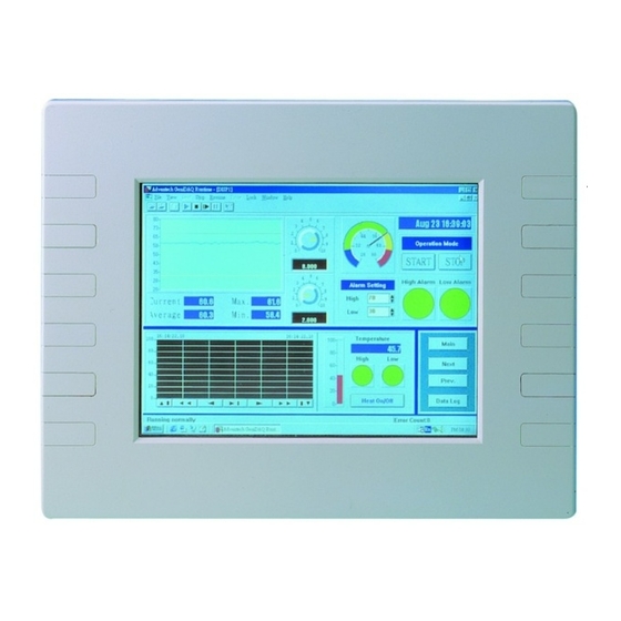
1.3 Front View The front view of the PPC-A84 is shown below: Power Indicator Figure 1-1: Front view of the PPC-A84 Chapter 1 General Information... -
Page 22: Dimensions
1.4 Dimensions The PPC-A84 can be placed on a shelf or a table, or mounted into a panel. Cutout panel dimensions are as follows: Figure 1-2: Dimensions of the PPC-A84 PPC-A84 User's Manual... -
Page 23: Cutout Dimensions(Suggestion)
1.5 Cutout Dimensions(Suggestion) The PPC-A84 will stand on a shelf or a table, or you can mount it into a panel. Cutout panel dimensions are the following: Figure 1-3: Dimensions of cutout and panel mounting holes Chapter 1 General Information... -
Page 24: Panel Mounting
1.6 Panel Mounting If you decide to panel mount your PPC-A84, Please find four screws and four nuts in the accessory box. To mount the PPC-A84 into a panel: 1. Removed the four caps from the front mask. 2. Insert the screws from the front side into the holes and tighten then with the nuts in the back side. -
Page 25: Universal Mounting Arm (Optional)
The universal arm of PPC-A84 allows you to easily cope with different applications restrains while installing the system. Simply grasp the PPC-A84, position it to remove glare, adjust to the most comfortable viewing angle, fix it with screws and everything is done. -
Page 26: Figure1-6: Mounting With Universal Arm (Ii)
Figure1-6: Mounting with universal arm (II) Stand mounting : The PPC-A84 can be held on the movable stand for those applica- tions with mobility and flexibility considerations, such as the bedside monitoring system in the hospitals. -
Page 27: Chapter 2 System Setup
System Setup • A Quick Tour of the Panel PC • Preparing for First-time Usage • Installation Procedure • Installing I/O Equipment • How to Install the software to HDD • Running the BIOS Setup Program • Installing the System Software •... -
Page 28: A Quick Tour Of The Panel Pc
When you place the panel PC upright on the desktop, its front panel appears as shown in Figure 2-1. Figure 2-1: Front view of the panel PC PPC-A84 User's Manual... -
Page 29: Figure 2-2: Top Side View Of The Panel Pc
When you look at the top side of the panel PC, you will see two door for DC power supply, hard disk drive, and PCMCIA expansion sockets, as shown in Fig. 2-2. Figure 2-2: Top side view of the panel PC Chapter 2 System Setup... -
Page 30: Figure 2-3: Rear View Of The Panel Pc
Figure 2-3: Rear view of the panel PC a. Heatsink b. Power switch button c. Power inlet connector d. 34-pin FDD connector e. 4-pin power connector for FDD/IDE devices f. 40-pin IDE connector for 3.5" HDD or CD-ROM PPC-A84 User's Manual... -
Page 31: Figure 2-4: I/O Section Of The Panel Pc
Figure 2-4: I/O section of the panel PC a. Serial COM1 port f. VGA port b. Serial COM2 port g. Ethernet port c. PS/2 keyboard h. USB port connector i. Line in d. mouse connector j. Microphone in e. Parallel port k. -
Page 32: Figure 2-5: Install Or Remove The Power Supply,Hdd Drive,Pcacia Module
The power supply, HDD drive and PCMCIA module are removable and easy to change and maintain. DC24 V or 12V Power Supply Optional PCMCIA module plug-in module for 2.5" Hard Drive Figure2-5: Install or remove the power supply,HDD drive,and PCMCIA module PPC-A84 User's Manual... -
Page 33: Preparing For First-Time Usage
2.2 Preparing For First-time Usage Before you start to set up the panel PC system, you should have at least the following items ready: • Power inlet cable (in the accessory box) • Male contact pin x 3 and female contact pin x 3 (in the accessory box) •... -
Page 34: Connecting The Insulator To Your Power Sources
Pin 1 should go into the positive DC power input ( + ), pin 2 connects to the frame ground ( G ), and pin 3 should be plugged into the negative DC power input ( - ). PPC-A84 User's Manual... - Page 35 Bottom tray STEP 3 : Mount the front part of the male insulator onto the bottom tray. Metal plate STEP 4: Use the metal plate and the two screws to secure the cables to the bottom tray. Please refer to the illustration above. Chapter 2 System Setup...
- Page 36 Upper cap STEP 5 Attach the upper cap to the bottom tray and secure it with the screws. STEP 6 Now that you have completed the assembly of the male insulator, plug it into the female insulator. PPC-A84 User's Manual...
-
Page 37: Installing A Primary 2.5" Hdd (Plug-In)
3. Put the HDD inside the black carrier. Screw the 4 screws to fix the HDD to carrier from two sides of the carrier. 4. Unscrew the two screws of the cover on the top side of PPC-A84 (See Fig.2-5). Open the cover. -
Page 38: Installing Dram (Sodimm)
4. Check to ensure that the SODIMM is correctly seated and all connector contacts touch. The SODIMM should not move around in its socket. Note: The modules can only fit into a socket one way and their gold pins must point down into the SODIMM socket. PPC-A84 User's Manual... -
Page 39: Installing I/O Equipment
1. Adjust the jumper setting of your IDE device to be a slave IDE device. 2. Unscrew the two attachment screws and detach the metal cover. 3. Connect the single end of the appropriate 40-pin cable to the PPC-A84 and connect the remaining end to your IDE device. -
Page 40: Ps/2 Keyboard And Ps/2 Mouse
Keyboard" under the "Halt On" selection. This allows no-keyboard operation in embedded system applications without the system halting under POST. Note that the mouse port on the PPC-A84 is a PS/2 mouse port. * Note: "All, But keyboard" is the default setting. -
Page 41: External Vga
2.4.4 External VGA The PPC-A84 can be connected to an external CRT monitor. To connect an external CRT monitor, connect the monitor's VGA cable to the PPC-A84's VGA port and connect the monitor's power cable to an AC outlet. The PPC- A84's external CRT display (VGA) connector is a standard 15-pin D-SUB connector commonly used for VGA. -
Page 42: Parallel Port
2.4.8 Ethernet The PPC-A84 is equipped with a high performance 32-bit Ethernet chipset which is fully compliant with the IEEE 802.3 100 Mbps CSMA/CD stan- dards. It is supported by major network operating systems. It is also both 100Base-T and 10Base-T compatible. -
Page 43: How To Install Software To The Hdd
2.5.3 Method 3: Use the COM or parallel port You can use Lap Link 6 or similar transmission software. Connect another PC to the PPC-A84 with an appropriate cable and transmit the software to the PPC-A84. 2.5.4 Method 4: Use a 3.5" HDD or CD-ROM Please refer to Section 2.4.1 "Installing one external IDE (3.5"... -
Page 44: Running The Bios Setup Program
Some distributors and system integrators may have already pre-installed system software prior to shipment of your panel PC. If required, insert your operating system's installation or setup diskette into the diskette drive until the release button pops out. PPC-A84 User's Manual... -
Page 45: Installing The Drivers
Note: The drivers and utilities used for the PPC-A84T panel PCs are subject to change without notice. If in doubt, check Advantech's web site or contact our application engineers for the latest information regarding drivers and utilities. Chapter 2 System Setup... - Page 46 PPC-A84 User's Manual...
-
Page 47: Chapter 3 The Engine Of Ppc-A84 (Pcm-5821)
The Engine of PPC-A84 (PCM-5821) • Introduction • Features • Jumpers and Connectors • Wake on LAN selction • CMOS clear • Watchdog timer configuration • COM2 RS-232/422/485setting • Buzzer enable... -
Page 48: Introduction
It also offers faster data access and longer MTBF than mechanical disk drives and is an ideal solution for critical commercial or industrial applications. The watchdog timer ensures the system will be reset if it stops due to a program bug or EMI problem. PPC-A84 User's Manual... -
Page 49: Features
3.2 Features • Ultra-compact size single board computer as small as a 3 1/2" hard disk drive (145 mm x 102 mm) • On-board NS GXm 233 MHz CPU • Up to 128 MB system memory by SODIMM (SDRAM) • On-board VGA/LCD controller •... -
Page 50: Jumpers And Connectors
A pair of needle-nose pliers may be helpful when working with jumpers. If you have any doubts about the best hardware configuration for your application, contact your local distributor or sales representative before you make any changes. PPC-A84 User's Manual... -
Page 51: Jumpers
3.3.2 Jumpers The motherboard of the panel PC has a number of jumpers that allow you to configure your system to suit your applications. The table below lists the function of each of the board jumpers. Table 3-1: Jumpers and their functions Label Function Power type of Lan... -
Page 52: Connectors
Compact Flash Disk secondary IDE connector CD IN I/O board connector I/O board connector Power FAN power connector External KBT2 CPU FAN power connector CN10 Power Switch CN20 Speaker and Microphone connector (Reserved) Power test connector (Reserved) Brightness VR (Reserved) PPC-A84 User's Manual... -
Page 53: Locating Jumpers And Connectors
3.3.4 Locating jumpers and connectors Power Fan Power test power connector (CN6) connector (PS1) Brightness VR(JS2) NS GXm processor CPU Fan power connector I/O board (CN8) connector (CN4) Buzzer enable (JP10) CD IN connector (CN3) Chipset Cx5530 I/O board connector (CN5) Primary IDE Power type Connector (J3) -
Page 54: Figure 3-2: Locating Jumpers And Connectors Pcm-5821 (Rear Side)
(JP2) Flat Panel Display Speaker and Connector (J2) Microphone connector (CN 20) Compact Flash Disk External secondary IDE KBT2 (CN7) Keyboard connector (CN2) connector Touchscreen (J4) connector (J5) Figure 3-2: Locating jumpers and connectors PCM-5821 (rear side) PPC-A84 User's Manual... -
Page 55: Wake On Lan Selection (Reserved) (Jp1)
Wake on LAN Selection (Reserved) (JP1) The PCM-5821 provides Wake-on LAN function when ATX power is used. To enable Wake-on LAN function, the JP1 should be set as shown below: Table 3-3: Wake-on LAN selection (JP1) *Normal Power Wake-on LAN * default setting CMOS Clear (JP2) Warning:... -
Page 56: 1Watchdog Activity Selection (Jp2)
COM2 can be configured to operate in RS-232/422/485 mode. This is done via JP3,JP4,and JP5. Table 3-6: COM2 RS-232/422/485 setting (JP3, JP4) *RS-232 RS-422/485 * default setting Table 3-7: COM2 RS-232/422/485 setting (JP5) *RS-232 RS-422 RS-485 *default setting PPC-A84 User's Manual... -
Page 57: Buzzer Enable (Jp10)
Buzzer enable (JP10) Table 3-8: Buzzer enable (JP10) *Enable Disable * default setting Chapter 3 The Engine of PPC-A84T (PCM-5821) - Page 58 PPC-A84 User's Manual...
-
Page 59: Chapter 4 Pci Bus Ethernet Interface
PCI Bus Ethernet Interface This chapter provides information on Ethernet configuration. • Introduction • Installation of Ethernet Driver Installation for WINDOWS 95 - Installation for WINDOWS 98 Installation for WINDOWS NT • Further Information... -
Page 60: Introduction
4.2 Installation of Ethernet Driver Before installing the Ethernet driver, note the procedures below. You must know which operating system you are using in your PPC-A84, and then refer to the corresponding installation flow chart. Then just follow the steps described in the flow chart. -
Page 61: Installation For Windows 95
4.2.1 Installation for WINDOWS 95 a. Select "Start", "Settings", "Control Panel". Click "Device Manager", Other Devices" item. c. Remove "PCI Ethernet Controller" item. a. Select "Start", "Settings","Control Panel" and "Network" icon. b. Click "Add" button. a. Select the "Adapter" item, and then click "OK"... - Page 62 Type the path "D\WIN95\ LAN". b. Click "OK" button a. Select "Realtek" RTL8139(A/B/C/ 8130) PCI Fast Ethernet. Click "OK" button. a. Click "OK" button. PPC-A84 User's Manual...
- Page 63 a. Insert "Win95" CD to load related files. b. Click "OK" button. a. Press "Yes" to start computer. E N D Chapter 4 PCI Bus Ethernet Interface...
-
Page 64: Installation For Windows 98
Driver button to update Ethernet driver. a. Click "next"button. a. Choose "Display a list of all the drivers in a specific location,so you can select the driver you want" option and then, click "next" button. PPC-A84 User's Manual... - Page 65 a. Highlight Network adapters", and then click "next" button. a. Click "Have Disk..button. a. Type "D:\Win98\ LAN" to install driver, and click "OK" button. a. Click the "OK" button to take the highlighted item. Chapter 4 PCI Bus Ethernet Interface...
- Page 66 Click "Next" button. a. Click "Finish" button to complete installation. a. Click "Yes" button to reboot system. E N D PPC-A84 User's Manual...
-
Page 67: Installation For Windows Nt
4.2.3 Installation for WINDOWS NT a. Select "Start", "Settings", "Control Panel", and then double click "Network" icon. b. Choose the "Adapters" label. c. Click the "Add" button. a.Press "Have Disk..." button. a. Insert the "Drivers and Utilities" CD-ROM. b. Fill the path "D:\WINNT\LAN". c. - Page 68 Click " OK" button. a. Finish network configuration a. Finish network configuration , and and then click the "close" button. then click the " OK" button. a. Press " Yes" button to restart your computer. PPC-A84 User's Manual...
-
Page 69: Further Information
4.3 Further Information Realtek web site: www.realtek.com.tw Advantech web site: www.advantech.com www.advantech.com.tw Chapter 4 PCI Bus Ethernet Interface... - Page 70 PPC-A84 User's Manual...
-
Page 71: Chapter 5 Pci Svga Setup
PCI SVGA Setup • Introduction • Installation of SVGA Driver Installation for WINDOWS 95 Installation for WINDOWS 98 Installation for WINDOWS NT • Further Information... -
Page 72: Introduction
5.1.1 Chipset The PPC-A84 Series uses a NS CX5530 chipset for its SVGA controller. It supports many popular 18-bit LCD displays and conventional analog CRT monitors. The VGA BIOS supports LCD. In addition, it also supports... - Page 73 Note1: The following windows illustrations are examples only. You must follow the flow chart instructions and pay attention to the instructions which then appear on your screen. Note2: The CD-ROM drive is disgnated as "D" throughout this chapter. Note3: <Enter> means pressing the "Enter" keyon the keyboard. Chapter 5 PCI SVGA Audio Setup...
-
Page 74: Installation For Windows 95
"Settings". b. Press "Advanced Properties". a. Choose the "Adapter" label. b. Press the "Change..." button. a. Press the "Have Disk" button. a. Insert the utility disc into the CD-ROM drive. b. Type: D:\WIN95\ VGA\". c. Press "OK". PPC-A84 User's Manual... - Page 75 a. Select the highlighted "Control Panel" item. b. Click the "OK" button. a. Cyrix Xpress Graphics (TM) appears in the adapter label. b. Click the "Apply" and then "OK" button. a. Press the "close" button. a. Press "Yes" to rebot. E N D Chapter 5 PCI SVGA Audio Setup...
-
Page 76: Installation For Windows 98
5.2.2 Installation for WINDOWS 98 a. Select " Start", "Run" b.Type" D:\win98\Vga&Audio\ Cyrixmed.exe" c. Press " OK" Press " Finish" button. Press " Next" button to take default setting. Take default setting " Typical" PPC-A84 User's Manual... - Page 77 Following the instruction to insert "Windows 98 CD-ROM ". Click " Finish" to complete installation. E N D Note: A common driver for Windows98 is used on both SVGA and Audio. While installing the SVGA driver for Windows98, as seen in the above procedure, the Audio driver will also be installed simultaneously.
-
Page 78: Installation For Windows Nt
Choose the "Settings " label. d. Press the "Display Type " button Press "Change... " button. Click the " Have Disk..." button. a. Insert the disc into the CD-ROM driver. b. Type "D:\WINNT\VGANT ". c: Press the "OK " button. PPC-A84 User's Manual... - Page 79 a. Select the hightlighted item. b. Press the " OK " button. Press "Yes" to process. a. Press " OK " to reboot. a. Repeat Step 1 in this manual. b. Adjust resolution and color. c. Click "Test" to see the result. d.
-
Page 80: Further Information
5.3 Further Information For further information about the PCI/SVGA and audio installation in your PPC-A84, including driver updates, troubleshooting guides and FAQ lists, visit the following web resources: NS web site: www.nsc.com Advantech web sites: www.advantech.com www.advantech.com.tw PPC-A84 User's Manual... -
Page 81: Chapter 6 Touchscreen
Touchscreen • Introduction • Installation of Touchscreen Driver Installation for DOS Installation for WINDOWS 95 Installation for WINDOWS 98 Installation for WINDOWS NT... -
Page 82: Introduction
To facilitate the installation of the touchscreen driver, you should read the instructions in this chapter carefully before you attempt installation. Note 1: The PPC-A84 uses the Dynapro 4-wire resistive touch- screen eqipped with Ronics controller board and drivers. When installing the touchscreen drivers, you will find the drivers in RonicsTouch directory. -
Page 83: Installation For Ms-Dos
6.2.1 Installation for MS-DOS 1. Change the directory to D\DOS\RONICSTOUCH\ 2. Type the command "Install C:" [Enter]. Installing system software automatically creates a directory named: "TSR411.PS2" in C drive. 3. Change the directory to C:\TSR411.PS2\. 4. Type "M" in the directory (TSR411.PS2) to install touchscreen driver. 5. -
Page 84: Installation For Windows 95
"Drivers and "Utilities" CD. b. Click "Start" button, and and then "Run." c. Type the path "D\Win95\Ronics- Touch\Setup.exe." Click "OK" button. a. Press "Install Now" button to install touchscreen driver. a. Click "OK" button to restart your computer. PPC-A84 User's Manual... - Page 85 a. Click touchscreen Control Panel version "R411.PS2" icon to enable the Touchscreen Control Panel. a. Press "Calibration" button to calibrate the touchscreen. E N D Chapter 6 Touchscreen...
-
Page 86: Installation For Windows 98
Click " Start " button, and then " Run ". c. Type the path " D:\win98\ c. Type the path"D:\Win98\ Ronics- Ronicstouch\WIN\setup.exe ". touch\setup.exe." a. Press "Ok" button. a. Click "Install Now" button. a. Click "Yes" button to restart your computer. PPC-A84 User's Manual... - Page 87 a. Press "Calibration" button to a. Touch targets to calibrate the calibrate the touchscreen. touchscreen controller. E N D E N D Chapter 6 Touchscreen...
-
Page 88: Installation For Windows Nt
Click "Start" button, and then " Run ". c. Type the path " D:\win98\ c. Type the path"D:\WinNT\ Ronics- Ronicstouch\WIN\setup.exe ". touch\setup.exe." a. Press "Ok" button. a. Click "Install Now" button. a. Click "Yes" button to restart your computer. PPC-A84 User's Manual... - Page 89 a. Press "Calibration" button to a. Touch targets to calibrate the calibrate the touchscreen. touchscreen controller. E N D Chapter 6 Touchscreen...
- Page 90 PPC-A84 User's Manual...
-
Page 91: Chapter 7 Audio Setup
Audio Setup • Introduction • Installation of Audio Driver Installation for WINDOWS 95 - Installation for WINDOWS 98 Installation for WINDOWS NT • Further Information... -
Page 92: Introduction
7.1 Introduction The PCM-5821 on-board audio interface provides high-quality stereo sound and FM music synthesis (ESFM) by using the NS CX5530 audio controller from National Semiconductor Corporation. The audio interface can record, compress, and play back voice, sound, and music with a built-in mixer control. -
Page 93: Installation For Windows 95
7.2.1 Installation for Windows 95 a. Remove items "PCI Multimedia Audio Device", and "Unknown Device" folder of Device Manager. b. Click "close" button to escape "Device Manager". Click "Add new hardware" icon, then "next". a. Select "No", and then click "Next"... - Page 94 a. Press "Have Disk.." button. a. Click "Add new hardware" icon, then "next". b. Type the path "D:\ WIN95\Audio". c. Click "OK" button. a. Select "Xpress Audio(TM) 16-bit sound". b. Press "OK" button. Click "finish" button. PPC-A84T User's Manual...
- Page 95 a. Insert "Win95" CD to load related files. b. Click "OK" button. a. Press "Yes" button to start your computer. E N D Chapter 5 PCI SVGA Audio Setup...
-
Page 96: Installation For Windows 98
7.2.2 Installation for WINDOWS 98 a. Select " Start", "R u n" b.Type" D:\win98\Vga&Audio\ Cyrixmed.exe" c. Press " O K" Press " Finish" button. Press " Next" button to take default setting. Take default setting " Typical" PPC-A84T User's Manual... - Page 97 Following the instruction to insert "Windows 98 CD-ROM ". Click " Finish" to complete installation. E N D Note: A common driver for WINDOWS 98 is used on both SVGA and Audio. Once you install the SVGA driver for WINDOWS 98 as Chapter 5.2.2., the audio driver is also installed simutaneously.
-
Page 98: Installation For Windows Nt
7.2.3 Installation for WINDOWS NT a. Select " Start ", " Settings ", " Control Panel ". b. Double click " Multimedia " icon. a. Select the " Devices " item. b. Click the " Add... " button. a. Choose " Unlisted or Updated Driver"... - Page 99 a. Insert " Drivers and Utilities " CD-ROM. b. Type the path " D:\winnt\audiont " c. Click " OK " button. a. Select the highlighted item. b. Press the " Ok " button. a. Change MPU 401I/O address to disable by pull down manual. b.
-
Page 100: Further Information
Press the " Restart Now " button to reboot your computer. E N D 7.3 Further Information For further information about the audio installation in your PPC-A84, including driver updates, troubleshooting guides and FAQ lists, visit the following web resources: NS web site: www.nsc.com Advantech web site: www.advantech.com... -
Page 101: Chapter 8 Award Bios Setup
Award BIOS Setup This chapter describes how to set BIOS configuration data. -
Page 102: Award Bios Setup
8.1 Award BIOS Setup The PPC-A84 comes with an Award BIOS chip that contains the ROM setup for your system. This chip serves as an interface between the processor and the rest of the mainboard's components. This chapter explains the informa- tion contained in the setup program and tells you how to modify the settings according to your system configuration. -
Page 103: Standard Cmos Setup
A setup program, built into the system BIOS, is stored in the CMOS RAM that allows the configuration settings to be changed. This program is execut- ed when the user changes the system configuration; when the user changes the system backup battery; or when the system detects a configuration error and asks the user to run the setup program. -
Page 104: Hard Disk Configurations
8.3.1 Hard Disk Configurations T Y P E : T Y P E : T Y P E : T Y P E : T Y P E : Select from 1 to 45 to fill the remaining fields with predefined values for disk drives. -
Page 105: Bios Features Setup
8.4 BIOS Features Setup Figure 8-3: BIOS features setup screen Moving around the BIOS Features and Chipset Features setup programs works the same way as moving around the Standard CMOS setup program. (Refer to the next section for Chipset Features setup.) The BIOS Features setup program is shown above. - Page 106 Quick Power On Self T Quick Power On Self T Quick Power On Self Test Quick Power On Self T Quick Power On Self T When enabled, allows the BIOS to bypass the extensive memory test. The options are: Disabled (Default), Enabled. Boot Sequence Boot Sequence Boot Sequence...
- Page 107 T T T T T ypematic Rate (Chars/Sec) ypematic Rate (Chars/Sec) ypematic Rate (Chars/Sec) ypematic Rate (Chars/Sec) ypematic Rate (Chars/Sec) Sets the rate of a character repeat when the key is held down. The options are: 6 (Default), 8, 10, 12, 15, 20, 24, 30. T T T T T ypematic Delay (msec) ypematic Delay (msec) ypematic Delay (msec)
-
Page 108: Chipset Features Setup
8.5 Chipset Features Setup Figure 8-4: Chipset features setup screen 16-bit/8-bit I/ORecovery (CLK) 16-bit/8-bit I/ORecovery (CLK) 16-bit/8-bit I/ORecovery (CLK) 16-bit/8-bit I/ORecovery (CLK) 16-bit/8-bit I/ORecovery (CLK) The options are: 1(Default), 2,...16 USB Contr USB Controller/ USB Legency Support USB Contr oller/ USB Legency Support oller/ USB Legency Support oller/ USB Legency Support USB Contr... -
Page 109: Power Management Setup
Video Memory Size Video Memory Size Video Memory Size Video Memory Size Video Memory Size The video memory size is set by the manufacturer, depend on how many video memory on board. The options are: 1.5M (Default), 2.5M. Flat Panel Status Flat Panel Status Flat Panel Status Flat Panel Status... - Page 110 Power Management Power Management Power Management Power Management Power Management When enabled, allows you to use Power Management features. The options are: Disabled (Default), Max Saving, Min Saving, User define. Doze Speed (div by) Doze Speed (div by) Doze Speed (div by) Doze Speed (div by) Doze Speed (div by) The options are: 2 (Default), 1, 3, 4, 5, 6, 7, 8.
-
Page 111: Pnp/Pci Configuration Setup
Note: Under certain operating systems such as WINDOWS NT 4.0 (Build 1381), the CD auto-insertion feature might have some effect on power management. It is recommended that the CD-ROM drive use the secondary channel, and that the following Power Management Setup features be set: HDD &... -
Page 112: Load Bios Defaults
Reset Configuration Data Reset Configuration Data Reset Configuration Data Reset Configuration Data Reset Configuration Data When enabled, this feature allows the system to clear the last BIOS configu- ration data and then reset the data with the default BIOS configuration data. The options are: Disabled (Default), Enabled. -
Page 113: Load Setup Defaults
The BIOS defaults screen contains the most appropriate values of the system parameters that allow minimum system performance. 8.9 Load Setup Defaults Selecting this field loads the factory defaults for BIOS and Chipset Features. The system will automatically detect these defaults. 8.10 Integrated Peripherals Figure 8-8: Integrated peripherals screen Chapter 8... - Page 114 IDE HDD Block Mode IDE HDD Block Mode IDE HDD Block Mode IDE HDD Block Mode IDE HDD Block Mode This allows your hard disk controller to use the fast block mode to transfer data to and from your hard disk drive (HDD). The options are: Enabled (Default), Disabled.
- Page 115 WDT Active When Power ON WDT Active When Power ON This is Advantech's patented watchdog function which can reboot the system should the computer hang in the BIOS checkup. The options are: 62 sec (Default), Disabled, 31 sec, 15 sec.
-
Page 116: Password Setting
The options for Port 3 are: 3E8/IRQ10 (Default), 2E8/IRQ5, Disabled. The options for Port 4 are: 2E8/IRQ5 (Default), Disabled, 3E8/IRQ10. 8.11 Password Setting To enable the password setting, select the item from the Standard CMOS Setup. You will be prompted to create your own password. Type your password up to eight characters and press "Enter". -
Page 117: Save And Exit Setup
8.13 Save and Exit Setup Figure 8-9: Save and exit setup screen After you have made changes in the BIOS setup, press "Esc" to return to the main menu. Move the cursor to "Save and Exit Setup", or press "F10" and then press "Y", to change the CMOS Setup. - Page 118 PPC-A84T User's Manual...
-
Page 119: Appendix A Programming The Watchdog Timer
Programming the Watchdog Timer The PPC-A84 is equipped with a watch- dog timer that resets the CPU or generates an interrupt if processing comes to a standstill for any reason. This feature ensures system reliability in industrial standalone or unmanned environments. -
Page 120: Programming The Watchdog Timer
A.1 Programming the Watchdog Timer To program the watchdog timer, you must write a program which writes I/O port address 443 (hex). The output data is a time interval value. The value range is from 01 (hex) to 3E (hex), and the related time interval is from 1 sec. - Page 121 The following example shows how you might program the watchdog timer in BASIC: Watchdog timer example program OUT &H443, data REM Start and restart the watchdog GOSUB 1000 REM Your application task #1, OUT &H443, data REM Reset the timer GOSUB 2000 REM Your application task #2, OUT &H443, data REM...
-
Page 123: Appendix B Full Disassembly Procedures
Full Disassembly Procedures... -
Page 124: Full Disassembly Procedures
B.1 Full Disassembly Procedures If you want to completely disassemble the panel PC, follow the step-by-step procedures below. Users should be aware that Advantech Co., Ltd. takes no responsibility whatsoever for any problems or damage caused by the user disassembly of the panel PC. Make sure the power cord of the panel PC is unplugged before you start disas- sembly. -
Page 125: Figure B-1: Disassembly Steps 1 - 4
HDD/FDD cover plate Step 1 & I/O bracket Step 2 HDD/FDD slot plat I/O Board Riser Board Step 3 Back cover Step 4 CPU board bracket Figure B-1: Disassembly steps 1 - 4 Appendix C Full Disassembly Procedures... - Page 126 5. Unscrew the five screws on the touchscreen control board and touchscreen control board bracket, then remove both components. 6. Detach the inverter by unscrewing the screw located on the right corner of the inverter. 7. Unscrew the rest of the screws on the motherboard to disassemble the motherboard from the CPU board bracket.
-
Page 127: Figure B-2: Disassembly Steps 5 - 7
CPU board bracket Step 6 Inverter Step 7 Motherboard Touchscreen control board bracket Step 5 Touchscreen control board Figure B-2: Disassembly steps 5 - 7 Appendix C Full Disassembly Procedures... - Page 128 8. Remove the front bezel carefully by a flat screwdriver. 9. Unscrew the six screws on the LCD holding plate to seperate the LCD cabinet and LCD holding plate. 10. Detach the LCD cabinet. 11. Detach the LCD by unscrewing the four screws located on each of the corners.
-
Page 129: Figure B-3: Disassembly Steps 8 - 12
Step 10 LCD cabinet Step 11 Step 9 LCD holding plate Step 12 Touchscreen Step 8 Front bezel Figure B-3: Disassembly steps 8 - 12 Appendix C Full Disassembly Procedures... - Page 130 PPC-123 User’s Manual...
-
Page 131: Appendix C Pin Assignments
Pin Assignments • Inverter Power Connector (J1) • Flat Panel Display Connector (J2) • Primary IDE Connector (J3) • Keyboard Connector (J4) • Internal Touchscreen Connector (J5) • CompactFlash™ Disk Secondary IDE Connector (CN2) • CD IN (CN3) • Power Fan Power Connector (CN6) •... -
Page 132: Inverter Power Connector (J1)
C.1 Inverter Power Connector (J1) Table C-1: Inverter power connector (J1) Signal +12 V ENABKL C.2 Flat Panel Display Connector (J2) Table C-2: Flat panel display connector (J2) Signal Signal VDDSAFE5 VDDSAFE5 VDDSAFE3 VDDSAFE3 Vcon PPC-A84 User’s Manual... -
Page 133: Primary Ide Connector (J3)
SHFCLK M/DE EVEN CLK ENABKL C.3 Primary IDE Connector (J3) Table C-3: Primary IDE connector (J3) Pin Signal Signal IDE RESET # DATA 7 DATA 8 DATA 6 DATA 9 DATA 5 DATA 10 DATA 4 DATA 11 DATA 3 DATA 12 DATA 2 DATA 13... -
Page 134: Keyboard Connector (J4)
ADDR 1 ADDR 0 ADDR 2 HDD SELECT 0 # HDD SELECT 1 # IDE ACTIVE 0 # # low active C.4 Keyboard Connector (J4) Table C-4: Keyboard Connector (J4) Signal EXT_ KBDAT2 PC_KBDAT EXT_KBDAT1 PC_KBCLK EXT_KBCLK1 EXT_KBCLK2 PPC-A84 User’s Manual... -
Page 135: Internal Touchscreen Connector(J5)
C.5 Internal Touchscreen Connector(J5) Table C-5: Internal Touchscreen Connector (J5) Signal -DCD4 -DSR4 RX4B -RTS4 -CTS4 -DTR4 -R14 PC_MSDAT EXT_MSDAT PC_MSCLK EXT_MSCLK Appendix D Pin Assignments... -
Page 136: Comapctflash™ Disk Secondary Ide Connector (Cn2)
C.6 ComapctFlash™ Disk Secondary IDE Connector (CN2) Table C-6: CompactFlash™ Disk Secondary IDE Connector (CN2) Signal Signal DATA3 DATA11 DATA4 DATA12 DATA5 DATA13 DATA6 DATA14 DATA7 DATA15 -CS0S -CS1S -IIOR1 -IIOW1 IIRQ15 -IRST IIRDY1 IDRQ1 -IIACK1 -HDLED DATA0 PPC-A84 User’s Manual... -
Page 137: Cd In (Cn3)
DATA1 DATA8 DATA2 DATA9 DATA10 C.7 CD IN (CN3) Table C-7: CD IN (CN3) Signal CD_INR CD_GND CD_INL CD_GND C.8 Power Fan Power Connector (CN4) Table C-8: Power Fan Power Connector (CN6) Signal FAN_CTL 12 V FAN_DET Appendix D Pin Assignments... -
Page 138: External Kbt2 Connector (Cn7)
C.9 External KBT2 Connector (CN7) Table C-9: CPU Fan Power Connector (CN7) Signal EXT_KBDAT2 EXT_KBCKL2 C.10 CPU Fan Power Connector (CN8) Table C-10: CPU fan power connector (FAN1) Signal +12 V FAN_DET PPC-A84 User’s Manual... -
Page 139: Power Switch Connector (Cn10)
C.11 Power Switch Connector (CN10) Table C-11: Power Switch Connector (CN10) Signal SUS_LED -FPRST -FPSW -FPSLP C.12 Speaker and Microphone Connector (CN20) Table C-12: Speaker and Microphone Connector (CN20) Signal LINOUT_L GNDADD GNDADD LINOUT_R GNDADD MIC_IN Appendix D Pin Assignments... -
Page 140: Power Test Connector (Ps1)
C.13 Power Test Connector (PS1) Table C-13: Power Test Connector (PS1) Signal Signal 3ATX 3ATX 3ATX -12 V -PSON -PWROK -5 V 5 VSB 12 V PPC-A84 User’s Manual... -
Page 141: Com2
C.14 COM2 Table C-14: COM2 Signal RS-232 RS-422 RS-485 DATA- DATA+ Appendix D Pin Assignments... -
Page 142: External Ide Connector
DATA12 DATA2 DATA13 DATA1 DATA14 DATA0 DATA15 SIGNAL GND HDD 0 IO WRITE IO READ HD READY HDACK 0# IRQ14 ADDR1 ADDR 0 ADDR 2 HDD SELECT 0# HDD SELECT 1# IDE ACTIVE 0# * Low active PPC-A84 User’s Manual... -
Page 143: External Floopy Drive Connector
C.16 External Floopy Drive Connector Table C-16: External floppy drive connector Signal Signal DENSITY SELECT* DRIVE TYPE INDEX* MOTOR 0* DRIVE SELECT 1* DRIVE SELECT 0* MOTOR 1* DIRECTION* STEP* WRITE DATA* WRITE GATE* TRACK 0* WRITE PROTECT* READ DATA* HEAD SELECT* DISK CHANGE* * Low active... -
Page 144: External Fdd And Hdd Power Connector
060-06F 8042 (keyboard Controller) 070-07F Real-time clock, non-maskable interrupt (NMI) mask 080-09F DMA page register, 0A0-0BF Interrupt controller 2 0C0-0DF DMA controller Clear math co-processor Reset math co-processor 0F8-0FF Math co-processor 1F0-1F8 Fixed disk 200-207 Game I/O PPC-A84 User’s Manual... - Page 145 278-27F Parallel printer port 2 (LPT 3) 2F8-2FF Serial port 2 300-31F Prototype card 360-36F Reserved 378-37F Parallel printer port 1 (LPT 2) 380-38F SDLC, bisynchronous 2 3A0-3AF Bisynchronous 1 3B0-3BF Monochrome display and printer adapter(LPT1) 3C0-3CF Reserved 3D0-3DF Color/graphics monitor adapter 3F0-3F7 Diskette controller 3F8-3FF...
- Page 146 PPC-A84 User’s Manual...
Need help?
Do you have a question about the PPC-A84 and is the answer not in the manual?
Questions and answers