
Related Manuals for Advantech PPC-L128T


Summary of Contents for Advantech PPC-L128T
- Page 1 User Manual PPC-L128T Intel® Atom N270 Processor- based Fanless Panel PC with 12.1" TFT-LCD...
- Page 2 No part of this manual may be reproduced, copied, translated or transmit- ted in any form or by any means without the prior written permission of Advantech Co., Ltd. Information provided in this manual is intended to be accurate and reliable.
-
Page 3: Declaration Of Conformity
Consult the dealer or an experienced radio/TV technician for help. Warning! Any changes or modifications made to the equipment which are not expressly approved by the relevant standards authority could void your authority to operate the equipment. PPC-L128T User Manual... -
Page 4: Packing List
If any of these items are missing or damaged, contact your distributor or sales repre- sentative immediately. Additional Information and Assistance Visit the Advantech web site at www.advantech.com where you can find the lat- est information about the product. Contact your distributor, sales representative, or Advantech's cus- tomer service center for technical support if you need additional assistance. -
Page 5: Safety Instructions
The sound pressure level at the operator's position according to IEC 704-1:1982 is no more than 70 dB (A). DISCLAIMER: This set of instructions is given according to IEC 704-1. Advantech disclaims all responsibility for the accuracy of any statements contained herein. - Page 6 PPC-L128T User Manual...
-
Page 7: Table Of Contents
System Setup ........7 A Quick Tour of the Panel PC ..............8 Figure 2.1 Front view of PPC-L128T panel PC ......8 Figure 2.2 Rear view of Panel PC ..........8 Figure 2.3 Side view of the panel PC .......... 9 Figure 2.4 Bottom view of the panel PC ........ - Page 8 PCI Express Bus connector (CN16) ............29 Table A.9: PCIExpress pin assignments ........29 A.10 How to setup Teaming function on PPC-L128/L157....... 30 A.10.1 Team together ................30 A.10.2 Dismiss! ..................35 A.10.3 TESTING ..................37 PPC-L128T User Manual viii...
-
Page 9: Chapter 1 General Information
Chapter General Information This chapter gives background information on the PPC-L128T panel PC. Sections include: Introduction General Specifications LCD Specifications Dimensions... -
Page 10: Introduction
IDE connector (for CF card), One SATA connector for HDD and one for ODD,and an PCI/PCIe expansion socket, the PPC-L128T is as compact and user friendly as a multifunction computer. In addition, its “fit anywhere” design makes it very flexible and able to be used in many different kinds of installations. -
Page 11: Vga/Lcd Interface
Teaming Function: Support Teaming Function(refer to A.10) 1.2.6 Touchscreen (Optional) Type Analog Resistive Resolution Continuous Light Transmission Controller USB interface Power Consumption <5 V @ 60 mA Software Driver Supports Windows 2000/XP Durability 35 million (touches in a lifetime) PPC-L128T User Manual... -
Page 12: Optional Modules
The color LCD display installed in the panel PC is high-quality and reli- able. However, it may contain a few defective pixels which do not always illuminate. With current technology, it is impossible to completely eliminate defective pixels. Advantech is actively working to improve this technology. PPC-L128T User Manual... -
Page 13: Dimensions
Dimensions Unit: mm [inch] Figure 1.1 Dimensions of PPC-L128T PPC-L128T User Manual... - Page 14 PPC-L128T User Manual...
-
Page 15: Chapter 2 System Setup
Chapter System Setup This chapter details system setup on the PPC-L128T panel PC. Sections include: A Quick Tour of the Panel PC Installation procedures Running the BIOS Setup Pro- gram Installing System Software Installing the Drivers... -
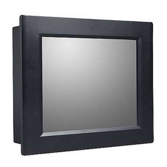
Page 16: A Quick Tour Of The Panel Pc
When you place the panel PC upright on the desktop, its front panel appears as shown in Figure 2.1. Figure 2.1 Front view of PPC-L128T panel PC When you turn the panel PC around and look at its rear cover, you will find the I/O section as shown in Fig. -
Page 17: Figure 2.3 Side View Of The Panel Pc
Before you start the computer, please connect the Y-shaped adaptor to the PS/2 mouse and keyboard port on the I/O section of the panel PC, then connect the nec- essary mouse or keyboard to the Y-shaped adapter or serial ports. PPC-L128T User Manual... -
Page 18: Switching On The Power
(POST). If an error occurs, an error message will be displayed on screen, and you will be prompted to run the setup program. If you want to change the setup of BIOS, refer to Chapter 9 for more detailed informa- tion. PPC-L128T User Manual... -
Page 19: Installing System Software
You can use the Ethernet port to download software to the HDD. 2.4.2 Method 2: Use the COM You can use Lap Link 6 or similar transmission software. Connect another PC to the PPC-L128T with an appropriate cable and transmit the software to the PPC-L128T. 2.4.3 Method 3: Use a DVD-RW If required, insert your operating system's installation or setup diskette into the dis- kette drive until the release button pops out. - Page 20 PPC-L128T User Manual...
-
Page 21: Chapter 3 Hardware Installation And Upgrading
Chapter Hardware Installation and Upgrading This chapter details installing the PPC- L128T panel PC hardware. Sections include: Overview of Hardware Installa- tion and Upgrading Installing the 2.5" Hard Disk Drive (HDD) Installing the battery pack... -
Page 22: Introduction
Connect the HDD cable to the PC board (CN5&CN6). Plug the other end of the cable into the SATA hard drive. Put the plastic rear cover on and tighten the screws. Plastic rear cover Figure 3.1 Installing primary 2.5" HDD PPC-L128T User Manual... -
Page 23: Installing The Battery Pack
Pull up the battery door cover on the right bottom of PPC-L128T. Put the battery pack in, and then connect the battery cable to battery connector in the PPC-L128T. Make sure the red wire corresponds to Pin 1 on the connec- tor. - Page 24 PPC-L128T User Manual...
-
Page 25: Chapter 4 Jumper Settings And Connectors
Chapter Jumper Settings and Connectors This chapter tells how to set up the panel PC hardware, including instructions on setting jumpers and connecting peripherals, switches and indicators. Be sure to read all the safety precautions before you begin the installation procedures. -
Page 26: Jumpers And Connectors
A pair of needle-nose pliers may be helpful when working with jumpers. If you have any doubts about the best hardware configuration for your application, contact your local distributor or sales representative before you make any changes. PPC-L128T User Manual... -
Page 27: Jumpers And Connectors
4.1.2 Jumpers and connectors The motherboard of the PPC-L128T has a number of jumpers and connectors that allow you to configure your system to suit your applications. The table below lists the function of each of the board’s jumpers. Table 4.1: Jumpers and Connector functions... -
Page 28: Locating Jumpers And Connectors
4.1.3 Locating jumpers and connectors Figure 4.1 Jumpers and Connectors on the PPC-L128T motherboard CMOS Clear for External RTC (CN13(2-3)) Warning! To avoid damaging the computer, always turn off the power supply before setting "Clear CMOS". Set the jumper back to "Normal operation"... -
Page 29: Com1/Com2/Com3 Pin 9 Output Setting (Cn20&Cn21)
LCD panel power setting The panel PC's AGP SVGA interface supports 12V LCD displays. The LCD cable already has a built-in default setting. You do not need to adjust any jumper or switch to select the panel power. PPC-L128T User Manual... - Page 30 PPC-L128T User Manual...
-
Page 31: Appendix A I/O Pin Assignments
Appendix I/O Pin Assignments... -
Page 32: Keyboard And Ps/2 Mouse Connector (Cn27)
+5 V KB_CLK MS-CLK USB port (CN19) Table A.2: USB port (CN19) Signal +V5_USB DATA- DATA+ +V5_USB DATA- DATA+ COM1 RS-232 serial port (CN37) Table A.3: COM1 RS-232 serial port (CN37) Signal Signal DCD# DTR# DSR# RTS# CTS# PPC-L128T User Manual... -
Page 33: Com2 (Cn28)
COM2 (CN28) Table A.4: COM2 (CN28) Signal RS-232 RS-422 RS-485 DATA- DATA+ COM3 RS-232 serial port (CN38) Table A.5: COM3 RS-232 serial port (CN38) Signal Signal DCD# DTR# DSR# RTS# CTS# PPC-L128T User Manual... -
Page 34: Gpio Port (Cn29)
GPIO port (CN29) Table A.6: GPIO port (CN29) GPIO0 GPIO1 GPIO2 GPIO3 GPIO4 GPIO5 GPIO6 GPIO7 VGA Connector (CN39) Table A.7: VGA connector (CN39) Signal GREEN BLUE SPDAT HSYNC VSYNC SPCLK PPC-L128T User Manual... -
Page 35: Pci Bus Connector (Cn18)
PCI Bus connector (CN18) Figure A.1 PCI connector PPC-L128T User Manual... -
Page 36: Table A.8: Pci Pin Assignments
Table A.8: PCI pin assignments Signal Signal IOCHK IRQ9 -5 V DRQ2 -12 V +12 V IORDY SA19 SA18 SA17 SA16 DACK3 SA15 DRQ3 SA14 DACk1 SA13 DRQ1 SA12 RFSH SA11 SCLk SA10 IRQ7 IRQ6 IRQ5 IRQ4 IRQ3 DACk2 PPC-L128T User Manual... -
Page 37: Pci Express Bus Connector (Cn16)
PCI Express Bus connector (CN16) Table A.9: PCIExpress pin assignments Signal Signal +V12 +V12 +V12 +V12 +V12 SMB_CLK SMB_DATA +V3.3 +V3.3 +V3.3 +V3.3SB PLTRST# PCIE_WAKE# CLK_PCIE+ CLK_PCIE- PCIE_TX+ PCIE_TX- PCIE_RX+ PCIE_RX- PRSNT# PPC-L128T User Manual... -
Page 38: How To Setup Teaming Function On Ppc-L128/L157
A.10 How to setup Teaming function on PPC-L128/ L157 A.10.1Team together Step 1. PPC-L128/L157 supports dual LAN function with each 1Gbps speed. PPC-L128T User Manual... - Page 39 Step 2. First, choose 1 LAN and open the properties panel. Then click on the Config- ure button. Step 3. Turn to Team page. Here you can create a new team or add to team. Click Create New Team. PPC-L128T User Manual...
- Page 40 Step 4. Name your team, and select the mode “Basic”. Step 5. Continue anyway. Step 6. The team has been created. PPC-L128T User Manual...
- Page 41 Step 7. Open the properties of another LAN, click “Add to Team” button. PPC-L128T User Manual...
- Page 42 Step 8. Choose the team this LAN should join in. Step 9. Now two LAN become one team with 2Gbps. PPC-L128T User Manual...
-
Page 43: A.10.2Dismiss
A.10.2Dismiss! Step 1. Open the configure page of teaming LAN. Two team members will show inside. PPC-L128T User Manual... - Page 44 Step 2. Choose the team member you want to kick out. Then click Remove Adapter button. Step 3. If you want to dismiss whole team. Click the Remove Team button and the team will be not available anymore. PPC-L128T User Manual...
-
Page 45: A.10.3Testing
A.10.3TESTING Step 1. Copy a big file to your disk through teaming LAN. Step 2. Unplug one cable. And the transmission of file still alive. Teaming function works!! PPC-L128T User Manual... - Page 46 No part of this publication may be reproduced in any form or by any means, electronic, photocopying, recording or otherwise, without prior written permis- sion of the publisher. All brand and product names are trademarks or registered trademarks of their respective companies. © Advantech Co., Ltd. 2009...
Need help?
Do you have a question about the PPC-L128T and is the answer not in the manual?
Questions and answers