Table of Contents
Advertisement
Quick Links
Advertisement
Table of Contents

Related Manuals for Advantech PPC-103


Summary of Contents for Advantech PPC-103
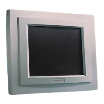
- Page 1 PPC-103 Celeron®/Pentium™III Panel PC with 10.4" LCD flat panel display...
- Page 2 Copyright Notice This document is copyrighted 2000 by Advantech Co. Ltd. All rights are reserved. Advantech Co., Ltd. reserves the right to make improvements to the products described in this manual at any time without notice. No part of this manual may be reproduced, copied, translated or transmitted in any form or by any means without the prior written permission of Advantech.
- Page 3 FCC Class B This equipment has been tested and found to comply with the limits for a Class B digital device, pursuant to Part 15 of the FCC Rules. These limits are designed to provide reasonable protection against harmful interference when the equipment is operated in a residential environment.
- Page 4 If you install or upgrade a CPU yourself, you must install the heat sink assembly from Advantech above the CPU in order to avoid heat damage to the CPU. The CPU and the heat sink are normally sold...
- Page 5 CPU. Due to tight constraints within the PPC-103’s housing, care must be taken to use the heat sink in the accessory box which will both cool the CPU and fit within the PPC-103. Thus you must buy a CPU without a fan attached.
- Page 6 The sound pressure level at the operator's position according to IEC 704-1:1982 is equal to or less than 70 dB(A). DISCLAIMER: This set of instructions is given according to IEC 704-1. Advantech disclaims all responsibility for the accuracy of any statements contained herein.
- Page 7 - Wenn das Gerät deutliche Anzeichen eines Defektes aufweist. Der arbeitsplatzbezogene Schalldruckpegel nach DIN 45 635 Teil 1000 beträgt 70 dB(A) oder weiger. DISCLAIMER: This set of instructions is given according to IEC704-1. Advantech disclaims all responsibility for the accuracy of any statements contained herein.
-
Page 8: Table Of Contents
Contents Chapter 1 General Information ....... 1 1.1 Introduction ..........2 1.2 Specifications ..........3 1.3 General ............3 1.4 Interface Standard PC functions ..... 3 1.5 I/O Arrangement ......... 8 1.6Cutout (Suggestion) ........9 1.7Mounting ............ 10 1.7.1 Panel mounting ..............10 1.7.2 Desktop stand (optional) ............ - Page 9 2.5 Installing Software to the HDD ....30 2.5.1 Method 1: Use the Ethernet ............ 30 2.5.2 Method 2: Use an FDD ............30 2.5.3 Method 3: Use the COM or parallel port ....... 30 2.5.4 Method 4: Use a 3.5" HDD or CD-ROM ........30 2.6 Exploded Diagram ........
- Page 10 4.2 CMOS Setup Utility ........48 4.3 Standard CMOS Setup ......49 4.3.1 Hard disk configurations ............49 4.4 BIOS Features Setup ....... 51 4.5 Chipset Features Setup ......54 4.6 Power Management Setup ..... 57 4.7 PNP/PCI Configuration Setup ....59 4.8 Load BIOS Defaults .........
- Page 11 6.2.1 Installation for Windows 95 ........... 82 6.2.2 Installation for Windows 98 ........... 83 6.2.3 Installation for Windows NT ........... 84 6.2.4 Installation for Windows 2000 ..........85 6.3 Further Information ......... 86 Chapter 7 Audio..........87 7.1 Introduction ..........88 7.2 Installation of Audio Driver .....
- Page 12 B.1 Introduction ..........114 B.2 Input Specifications ......114 B.3 Output Specifications ......114 B.4 Mechanical Specifications ....115 B.5 Environmental Specifications ..... 116 B.6 Features ..........116 International standards ..............116 APPENDIX C I/O Pin Assignments ..... 119 Keyboard connector (CN5-1) ............120 Mouse connector (CN5-2) ..............
- Page 13 Figure 2-11: PPC-103 exploded diagram ..........31 Figure 2-12: Installing/removing the PCM-9573 in the PPC-103 ..33 Figure 2-13: Installing/removing the I/O adapter in the PPC-103 ..32 Figure 2-14: Replacing the power supply ..........34 Figure 2-15: Replacing the cooling fan ..........35 Figure 3-1: Jumpers on the PPC-103 motherboard ......
- Page 14 Figure 4-9: IDE HDD auto detection screen ........64 Figure 4-10: Save and exit setup screen ..........65 Figure B-a: PPC-103 dimensions diagram ........115...
- Page 15 Table 1-1: PPC-103 series LCD specifications ........6 Table 3-1: Jumpers and their functions ..........39 Table 3-2: Connectors on the PPC-103 motherboard ......41 Table 3-3: Clear CMOS / External RTC (JP7) ........43 Table 3-4: COM2 RS-232/422/485 setting (JP2, JP3) ......43 Table 3-5: COM2 RS-232/422/485 setting (JP4) .........
-
Page 17: Chapter 1 General Information
General Information This chapter gives background information on the PPC-103. Sections include: • Introduction • Specifications • LCD Specifications • Dimensions • I/O Arrangement • Cutout (Suggestion) • Mounting... -
Page 18: Introduction
16-bit audio controller. This simple, complete, compact and highly integrated multimedia system lets you easily build a panel PC into your applications. By incorporating the PPC-103 into your project, your product development time will be shortened. The PPC-103 is a compact, network-compatible PC with extensive features to control a dedicated system in a wide variety of applica- tions. -
Page 19: General
• BIOS: AWARD 256KB Flash BIOS, supports Plug & Play, APM v1.2 • Chipset: Intel 82443BX/82371EB • 2nd level cache: 128 KB on CPU • RAM: Two 144-pin SODIMM sockets accept 16~256MB SDRAM • PCI Bus Master IDE interface: Supports two connectors (one internal, one external extension). - Page 20 • Software driver: Supports DOS, Windows 95/98, Windows NTand Windows 2000 • Durability: 30 million touch lifetime **Note: The PPC-103 with the optionally installed touchscreen will share COM4. Optional modules • CPU: Intel Celeron or Pentium III • Memory: 16/32/64/128/256 MB SODRAM •...
-
Page 21: Table 1-1: Ppc-103 Series Lcd Specifications
• Relative humidity: 10 ~ 95% @ 40 °C, non-condensing • Shock: 10G peak acceleration (11 msec duration) • Power MTBF: 50,000 hrs • Certification: Passed CE, FCC Class B, VCCI certification LCD Specifications Table 1-1: PPC-103 series LCD specifications PPC-103T PPC-103S Model Display type 10.4"... -
Page 22: Figure 1-1: Ppc-103 Panel Pc Dimensions
Dimensions Unit: mm Figure 1-1: PPC-103 panel PC dimensions PPC-103 User's Manual... -
Page 23: I/O Arrangement
External IDE port l. Light indicator f. AC inlet m. Ethernet port g. Parallel port * Three RS-232 (COM1, 3, 4) and one RS-232/422/485 (COM2) Figure 1-2: PPC-103 back panel I/O arrangement and cable connections Chapter 1 General Information... -
Page 24: Cutout (Suggestion)
Cutout (Suggestion) The PPC-103 will stand on a shelf or a table, or you can mount it into a panel. Cutout panel dimensions are as follows: Cutout for panel mount Unit: mm Figure 1-3: PPC-103 panel mounting cutout dimensions PPC-103 User's Manual... -
Page 25: Mounting
Mounting 1.7.1 Panel mounting If you decide to use a cutout within a panel to mount your PPC-103, we have included two panel-mount brackets. The brackets have two screws that fit in the keyhold slots on the panel PC. Slide the PPC-103 backwards into the panel opening. Attach the two mounting brackets by sliding the two screw heads into the keyhole slots on the rear cover. -
Page 26: Desktop Stand (Optional)
1.7.2 Desktop stand (optional) An optional stand is available for mounting the PPC as a desktop PC. The PPC-103 slides into the stand and is held in place by the screws provided. The compactness of the desktop-mounted PPC-103 saves desk space. -
Page 27: Wall-Mounting (Optional)
1. The wall-mounting attachment is comprised of three parts: one back bracket, one support bracket, and one mounting bracket. 2. First attach the back bracket to the rear cover of the PPC-103, securing it in place with four of the philips-head screws provided. - Page 28 PPC-103 User's Manual...
-
Page 29: Chapter 2 System Setup
System Setup • General • Removing Rear Panel • Installing Options • Installing I/O Equipment • Installing Software to the HDD • Exploded Diagram • PCM-9573 and I/O Adapter Replacement • Power Supply and Cooling Fan Replacement... -
Page 30: General
General The PPC-103 consists of a PC-based industrial computer that is housed in a protective cover. Your HDD, SDRAM, power supply and CPU are all readily accessible by removing the rear panel. Any maintenance or hardware upgrades can be carried out easily after removing the rear panel. -
Page 31: Removing Rear Panel
Figure 2-1: Removing the PPC-103's rear panel Because the CPU socket is fragile, only qualified engineers can install the CPU. If the customer breaks the CPU socket, Advantech is not responisble for the failure of this assembly, Chapter 2 System Setup... -
Page 32: Installing Options
Caution! When buying a CPU, do not include a fan and do not apply thermal jelly to the CPU for fan installation. The compact size of the PPC-103 prevents using a fan. Warning! Always disconnect the power cord from your PPC-103 when you are working on it. -
Page 33: Figure 2-2: Fan Cooling With Heatsink Assembly Installation
Figure 2-2: Fan cooling with heatsink assembly installation Chapter 2 System Setup... -
Page 34: Figure 2-3: Place Cpu Push Cover Over Cpu
5. Insert the flat-headed screwdriver into the side hole of the CPU upward perpendicular to the CPU as shown in Figure 2-4. Make sure the slightly bent screw driver head is pointing outward. Figure 2-4: Insert screw driver into the hole PPC-103 User's Manual... -
Page 35: Installing A Primary 2.5" Hdd (Internal)
2.3.2 Installing a primary 2.5” HDD (internal) You can attach one enhanced Integrated Device Electronics (IDE) hard disk drive to the PPC-103’s internal controller which uses a PCI local bus interface. The advanced IDE controller supports faster data transfer rates and allows the IDE hard disk drive to exceed 528 1. -
Page 36: Figure 2-6: Cpu Installation
Figure 2-6: CPU installation PPC-103 User's Manual... -
Page 37: Figure 2-7: Hdd Assembly
MB. The following are instructions for installation (Figure 2-7). Figure 2-7: HDD Assembly Chapter 2 System Setup... -
Page 38: Figure 2-8: Rubber Screwed Onto The Hard Disk
The finished hard disk assembly is shown in Figure 2-8. Figure 2-8: Rubber screwed onto the hard disk 2. Turn off the PPC-103 and remove the rear cover. 3. Connect the HDD flat cable (44-pin to 44-pin) from the hard disk to the PC board, as shown in Figure 2-9. Make sure that the red wire corresponds to pin 1 on the connector, which is labeled on the board. -
Page 39: Figure 2-9: Connect Flat Cable To The Hdd
cable should be folded as in Figure 2-6 to facilitate the installation. Figure 2-9: Connect flat cable to the HDD Chapter 2 System Setup... -
Page 40: Installing The Sdram Memory Module
You can install from 16 MB to 256 MB of SDRAM memory. The PCM-9573 provides two 144-pin SODIMM (Dynamic Inline Memory Module) sockets. Note: The module can only fit into a socket one way. Pin 1 of the PPC-103 User's Manual... - Page 41 SODIMM module must line up with the small arrowhead printed on the PCM-9573 next to the SODIMM socket. The golden pins of the module must point down into the SODIMM socket. 1. Ensure that all power sources are disconnected. 2. Slip the memory module into the socket at a 45 degree angle.
-
Page 42: Installing An Fdd
2.3.4 Installing an FDD Up to two floppy drives can be attached to the PPC-103's I/O controller. Any combination of 5¼" (360 KB and 1.2 MB) and/or 3½" (720 KB, 1.44 MB, and 2.88 MB) drives can be attached. A 34-pin FDD connector is located on the rear panel of the PPC-103. -
Page 43: Parallel Port Connection
ECP/EPP DMA channels (DMA1 and DMA3) can be selected via the BIOS setup. 2.4.4 PS/2 keyboard and PS/2 mouse The PPC-103 provides a PS/2 keyboard connector that supports a PS/2 style keyboard and a 5-pin DIN keyboard extension cable. In most cases, especially in embedded applications, a keyboard is not used. -
Page 44: Mic-In, Line-Out
* Note: "All, But keyboard" is the default setting. 2.4.5 Mic-in, line-out The PPC-103 contains an ESS 1938 chipset, which is a single, mixed-signal audio chip designed into the PPC-103. It provides high-quality stereo sound and FM music synthesis, and is compatible with Sound Blaster Pro version 3.01 voice and music functions. -
Page 45: External Vga
2.4.6 External VGA The PPC-103 can be connected to an external CRT monitor. To connect an external CRT monitor, connect the monitor's VGA cable to the PPC-103's VGA port and connect the monitor's power cable to an AC outlet. The... -
Page 46: Installing Software To The Hdd
Installing Software to the HDD Installing software requires an installed HDD. Software can be loaded in the PPC-103 using any of four methods: 2.5.1 Method 1: Use the Ethernet You can use the Ethernet port to download software to the HDD. -
Page 47: Exploded Diagram
Exploded Diagram Figure 2-11 shows all the components and parts that make up the PPC-103. Use it as a guide when assembling and disassembling your system. Figure 2-11: PPC-103 exploded diagram Chapter 2 System Setup... -
Page 48: Pcm-9573 And I/O Adapter Replacement
5. Some screws on your left hand side connect the I/O adapter to the PC, and also connect the adapter to the PCM-9573. Screw the screws into the panel. Figure 2-12: Installing/removing the PCM-9573 in the PPC-103 PPC-103 User's Manual... -
Page 49: Figure 2-13: Installing/Removing The I/O Adapter In The Ppc-103
You may change the jumper settings for RS-232/422/485 before installing te I/O adapter. Figure 2-13: Installing/removing the I/O adapter in the PPC-103 Chapter 2 System Setup... -
Page 50: Power Supply And Cooling Fan Replacement
Ensure that any replacement power supply matches the system's specifications. 3. The cooling fan is located inside the rear panel. You can remove the cooling fan by first removing the four screws (Figure 2-15). Figure 2-14: Replacing the power supply PPC-103 User's Manual... -
Page 51: Figure 2-15: Replacing The Cooling Fan
Figure 2-15: Replacing the cooling fan Chapter 2 System Setup... - Page 52 PPC-103 User's Manual...
-
Page 53: Chapter 3 Jumper Settings And Connectors
Jumper Settings and Connectors This chapter tells how to set up the panel PC hardware, including instructions on setting jumpers and connecting peripherals, switches and indicators. Be sure to read all the safety precautions before you begin the installation procedures. •... -
Page 54: Jumpers And Connectors
A pair of needle-nose pliers may be helpful when working with jumpers. If you have any doubts about the best hardware configuration for your application, contact your local distributor or sales representative before you make any changes. PPC-103 User's Manual... -
Page 55: Jumpers And Switch
3.1.2 Jumpers and switch The motherboard of the PPC-103 has a number of jumpers that allow you to configure your system to suit your applications. The table below lists the function of each of the board’s jumpers. Table 3-1: Jumpers and their functions... -
Page 56: Locating Jumpers And Switch
3.1.3 Locating jumpers and switch JP5: COM3/COM4 PIN 9 output type setting JP6: Watchdog timer action JP3: COM2 type select JP4: COM2 type select JP2: COM2 type select JP7: CMOS clear Figure 3-1: Jumpers on the PPC-103 motherboard PPC-103 User's Manual... -
Page 57: Connectors
3.1.4 Connectors Onboard connectors link the PPC-103 to external devices such as external hard disk drives or floppy drives. The table below lists the function of each of the board’s connectors. Table 3-2: Connectors on the PPC-103 motherboard Label Function... -
Page 58: Locating Connectors
J1: AT power connector J5: Front panel display control connector DIMM2: for 144P SO-DIMM (3.3V SDRAM) J2: TV connector CN3: 2.5" IDE connector J4: Speaker connector (Secondary/Master) J6: Touch screen control connector Figure 5-2: Locating connectors on the PPC-103 motherboard PPC-103 User's Manual... -
Page 59: Cmos Clear For External Rtc (Jp7)
3.3 CMOS Clear for External RTC (JP7) Warning: To avoid damaging the computer, always turn off the power supply before setting “Clear CMOS”. Set the jumper back to “Normal operation” before turning on the power supply. Table 3-3: Clear CMOS / External RTC (JP7) *Normal operation Clear CMOS * default setting... -
Page 60: Table 3-5: Com2 Rs-232/422/485 Setting (Jp4)
COM3 and COM4 are another set. Their selectable function is the same as the COM1/COM2 set. Table 3-6: Serial port default settings Port Address Range Interrupt COM1 2F8 ~ 2FF IRQ3 COM2 3F8 ~ 3FF IRQ4 COM3 3E8 ~ 3EF IRQ10 COM4 2E8 ~ 2EF IRQ5 PPC-103 User's Manual... -
Page 61: Com3 / Com4 Pin 9 Output Type Setting (Jp5)
3.4.2 COM3 / COM4 pin 9 output type setting (JP5) Table 3-8: COM3/COM4 pin 9 setting (JP5) *Normal operation +5 V output +12 V output * default setting Note: Pins 1, 3 and 5 are for COM3. Pins 2, 4 and 6 are for COM4. 3.5 VGA Interface The panel PC's AGP VGA interface can drive conventional CRT displays. -
Page 62: Watchdog Timer Configuration
When the watchdog timer activates (i.e. CPU processing has come to a halt), it can reset the system or generate an interrupt on IRQ11. This can be set via jumper JP6 as shown below: Table 3-11: Watchdog activity selection (JP6) *System reset IRQ11 * default setting PPC-103 User's Manual... -
Page 63: Chapter 4 Award Bios Setup
Award BIOS Setup This chapter describes how to set BIOS configuration data. -
Page 64: Award Bios Setup
4.1 Award BIOS Setup The PPC-103 comes with an Award BIOS chip that contains the ROM setup for your system. This chip serves as an interface between the processor and the rest of the mainboard's components. This chapter explains the information contained in the setup program and tells you how to modify the settings according to your system configuration. -
Page 65: Standard Cmos Setup
program is executed when the user changes the system configuration; when the user changes the system backup battery; or when the system detects a configuration error and asks the user to run the setup program. At power-on RAM testing, the message "Press DEL to enter Setup"... - Page 66 LBA mode, select "LBA" or "Large". However, if your hard disk supporting cylinder is more than 1024 MB and does not support the LBA function, you have to select "Large". If your hard disk supporting cylinder is below 1024 MB, select "Normal". PPC-103 User's Manual...
-
Page 67: Bios Features Setup
4.4 BIOS Features Setup Figure 4-3: BIOS features setup screen Moving around the BIOS Features and Chipset Features setup programs works the same way as moving around the Standard CMOS setup program. (Refer to the next section for Chipset Features setup.) The BIOS Features setup program is shown above. - Page 68 Allows the system BIOS to first try to boot the operating system from the selected disk drive. The options are: C, A, SCSI (Default) LS/ZIP, C C (only) SCSI, C, A SCSI, A, C F, A, SCSI E, A, SCSI D, A, SCSI PPC-103 User's Manual...
- Page 69 CDROM, C, A C, CDROM, A Swap Floppy Drive When enabled, allows you to switch the order in which the operating system accesses the floppy drives during boot-up. The options are: Disabled (Default), Enabled. Boot Up Floppy Seek When enabled, assigns the BIOS to perform floppy disk drive tests by issuing seek commands.
-
Page 70: Chipset Features Setup
BIOS ROM of each add-on card. The options are: Disabled (Default), Enabled. Chipset Features Setup Note: It is strongly recommended that setup items in this section NOT be changed, because advanced PPC-103 User's Manual... -
Page 71: Figure 4-4: Chipset Features Setup Screen
knowledge is required to effect such changes. Figure 4-4: Chipset features setup screen EDO CASX# MA Wait State Sets the EDO CASX# MA wait state. The options are: 1 (Default), 2. EDO RASX# Wait State Sets the EDO RASX# wait state. The options are: 1 (Default), 2. - Page 72 When disabled, the syatem operates normally. When enabled, the system can support lower-speed ISA devices. The options are: Disabled (Default), Enabled. Spread Spectrum When disabled, the syatem operates normally. When enabled, the spread spectrum will be set to 0.5% (CNTR). PPC-103 User's Manual...
-
Page 73: Power Management Setup
The options are: Disabled (Default), Enabled. Power Management Setup Figure 4-5: Power management setup screen Power Management When enabled, allows you to use Power Management features. The options are: Disabled (Default), Enabled. PM Control by APM The option "No" allows the BIOS to ignore the APM (Advanced Power Management) specification. - Page 74 The system will not enter Suspend mode, because this option is designated as "Disabled". HDD POWER Down Selecting "Disabled" will turn off the hard disk drive (HDD) motor. Selecting "1 Min.. 15 Min" allows you to define the HDD idle time PPC-103 User's Manual...
-
Page 75: Pnp/Pci Configuration Setup
before the HDD enters Power Saving Mode. The options "1 Min.. 15 Min" and "When Suspend" will not work concurrently. When the HDD is in Power Saving Mode, any access to the HDD will wake it up. The options are: Disabled (Default), 1 Min., 15 Min. PNP/PCI Configuration Setup Figure 4-6: PNP/PCI configuration setup screen PNP OS Installed... -
Page 76: Load Bios Defaults
Choose and use the MEM base address. The options are: N/A (Default), C800 ~ DC00. Assign IRQ for USB Assigns an IRQ for the USB. The options are: Disabled (Default), Enabled. Load BIOS Defaults Figure 4-7: Load BIOS defaults screen PPC-103 User's Manual... -
Page 77: Load Setup Defaults
The BIOS defaults screen contains the most appropriate values of the system parameters that allow minimum system performance. 4.9 Load Setup Defaults Selecting this field loads the factory defaults for BIOS and Chipset Features. The system will automatically detect these defaults. 4.10 Integrated Peripherals Figure 4-8: Integrated peripherals screen IDE HDD Block Mode... - Page 78 The options for Port 2 are: 2F8/IRQ3 (Default), 3E8/IRQ4, 2E8/IRQ3, Disabled, 3F8/IRQ4. Onboard Serial Ports 3 & 4 If the serial ports use the onboard I/O controller, you can modify your serial port parameters. The options for Port 3 are: 3E8/IRQ10 (Default), 2E8/IRQ5, Disabled. PPC-103 User's Manual...
-
Page 79: Password Setting
The options for Port 4 are: 2E8/IRQ5 (Default), Disabled, 3E8/IRQ10. Onboard Parallel Port If the parallel port uses the onboard I/O controller, you can modify your parallel port paramaters. When you select "Disabled", the next two setup items will disappear. The options are: 378/IRQ7 (Default), 3BC/IRQ7, 278/IRQ5, Disabled. -
Page 80: Ide Hdd Auto Detection
This feature allows you to set the parameters of up to four IDE HDDs. The option with "(Y)" is recommended by the system BIOS. You may also key in your own parameters instead of PPC-103 User's Manual... -
Page 81: Save And Exit Setup
setting them according to the system BIOS. After keying in all settings, press "Esc" to return to the main menu. For confirmation, enter the Standard CMOS Setup feature. 4.13 Save and Exit Setup Figure 4-10: Save and exit setup screen After you have made changes in the BIOS setup, press "Esc"... - Page 82 CMOS modifications: Quit Without Saving (Y/N) ? PPC-103 User's Manual...
-
Page 83: Chapter 5 Pci Bus Ethernet Interface
PCI Bus Ethernet Interface This chapter provides information on Ethernet configuration. • Introduction • Installation of Ethernet Driver - for Windows 95 - for Windows 98 - for Windows NT • Further Information... -
Page 84: Introduction
5.2 Installation of Ethernet Driver Before installing the Ethernet driver, note the procedures below. You must know which operating system you are using in your PPC-103, and then refer to the corresponding installation flow chart. Then just follow the steps described in the flow chart. You will quickly and successfully complete the installation, even if you are not familiar with instructions for Windows. -
Page 85: Installation For Windows 95
5.2.1 Installation for Windows 95 1. a. Select "Start," "Settings," "Control Panel," "System." b. Click "Device Manager" and "Other Devices." c. Remove "PCI Ethernet Controller." 2. a. Select "Start," "Settings," "Control Panel," and "Network" icons. b. Click the "Add" button. Chapter 5 PCI Bus Ethernet Interface... - Page 86 3. Select "Adapter" and then click the "Add" button. 4. Press the "Have Disk..." button. 5. a. Type the path “D:\PPC103\LAN\W95OSR2” b. Click the “OK” button. PPC-103 User's Manual...
- Page 87 6. a. Choose the highlighted “realteck RTL8139[A/B/C/ 8130]PCI Fast Ethernet” b. Press the “OK” button 7. a. Press the “Add...”button to select suitable services or protocol. b. Press the “OK” botton to finish network configuration. 8. Press the “Yes” button to restart your computer. Chapter 5 PCI Bus Ethernet Interface...
-
Page 88: Installation For Windows 98
5.2.2 Installation for Windows 98 1. a. Select "Start," "Settings," "Control Panel," "System." b. Click "Device Manager" and "Other Devices." c. Remove "PCI Ethernet Controller." 2 a. Select "Start," "Settings," "Control Panel," and "Network" icons. b. Click the "Add" button. PPC-103 User's Manual... - Page 89 3 Select "Adapter" and then click the "Add" button. 4. Press the "Have Disk" button. 5. a. Type the path “D:\PPC103\LAN\WIN98.” b. Click the “OK” button. Chapter 5 PCI Bus Ethernet Interface...
- Page 90 6. a. Choose the highlighted “Realteck RTL8139[A/B/C/ 8130]PCI Fast Ethernet NIC.” b. Press the “OK” button. 7. a. Press the “Add...” button to select suitable services or protocol. b. Press the “OK” button to fnish network configuration. PPC-103 User's Manual...
- Page 91 8. Press the “Yes” button to restart your computer. Chapter 5 PCI Bus Ethernet Interface...
-
Page 92: Installation For Windows Nt
5.2.3 Installation for Windows NT 1. a. Select “Start,” “Settings,” “Control,” and then double click the “Network” icon. b. Choose the “Adapters” label. c. Click the “Add” button. 2. Press “Have Disk.” PPC-103 User's Manual... - Page 93 3. a. Type the path “D:\PPC103\LAN\WINNT” b. Press the “OK” button. 4. a. Choose the hightlighted “RTL8139[A/B/C/8130] PCI Fast Ethernet Adapter.” b. Click the “OK” button. 5. Choose a stuitable RTL8139 Duplex mode for your application. Chapter 5 PCI Bus Ethernet Interface...
-
Page 94: Further Information
6. Finish the network configuration and then click the “OK” button. Further Information Realtek website: www.realtek.com.tw Advantech websites: www.advantech.com www.advantech.com.tw PPC-103 User's Manual... -
Page 95: Chapter 6 Pci Svga Setup
PCI SVGA Setup • Introduction • Installation of SVGA Driver - for Windows 95 - for Windows 98 - for Windows NT - for Windows 2000 • Further Information... -
Page 96: Introduction
6.1.3 Display types CRT and panel displays can be used simultaneously. The PPC-103 can be set in one of three configurations: on a CRT, on a flat panel display, or on both simultaneously. The system is initially set to simultaneous display mode. - Page 97 Complete the following steps to install the SVGA driver. Follow the procedures in the flow chart that apply to the operating system that you you are using within your PPC- 103. Important: The following windows illustrations are examples only. You must follow the flow chart instructions and pay attention to the instructions which then appear on your screen.
-
Page 98: Installation For Windows 95
6.2.1 Installation for Windows 95 1.a. Select “Start” and “Run” b. Enter the path “D:\PPC103\VGA\Win9x\setup.exe” c. Press “OK” 2. Press “Next” 3. Click “Finish” to complete the installation and restart your computer. PPC-103 User's Manual... -
Page 99: Installation For Windows 98
6.2.2 Installation for Windows 98 1.a. Select “Start” and “Run” b. Enter the path “D:\PPC103\VGA\Win9x\setup.exe" c. Press “OK” 2. Press “Next” 3. Click “Finish” to complete the installation and restart your computer. Chapter 6 PCI SVGA Setup... -
Page 100: Installation For Windows Nt
6.2.3 Installation for Windows NT 1.a. Select “Start” and “Run” b. Enter the path “D:\PPC103\VGA\Win9x\setup.exe” c. Press “OK” 2. Press “Next” 3. Click “Finish” to complete the installation and restart your computer. PPC-103 User's Manual... -
Page 101: Installation For Windows 2000
6.2.4 Installation for Windows 2000 1.a. Select "Start", "RUN" b. Enter the path "D:\PPC103\VGA\Win2000\Setup.exe" c. Press "OK" 2. Press "Next" Chapter 6 PCI SVGA Setup... -
Page 102: Further Information
3. When installation is completed, Click "Finish" to restart your computer. Further Information For further information about the AGP/SVGA installation in your PPC-103, including driver updates, troubleshooting guides and FAQ lists, visit the following web resources: Silicon Motion website: www.siliconmotion.com Advantech websites: www.advantech.com www.advantech.com.tw... -
Page 103: Chapter 7 Audio
Audio • Introduction • Installation of Audio Driver - for Windows 95/98 - for Windows NT - for Windows 2000... -
Page 104: Introduction
Before installing the audio driver, please take note of the procedures detailed below. You must know which operat- ing system you are using in your PPC-103, and then refer to the corresponding installation flow chart. Just follow the steps in the flow chart. You can quickly and successfully complete the installation, even though you are not familiar with instructions for Windows. -
Page 105: Installation For Windows 95/98
7.2.1 Installation for Windows 95/98 1. a. Select “Start” and “Run” b. Enter the driver path “D:\PPC103\Audio\Win9x(only)\Setup.exe” 2. Click “Next” to continue the installation 3. a. Select “Upgrade Drivers” b. Click “Next” Chapter 7 Audio... - Page 106 4. Click “Finish” to complete the installation and restart your computer. 5. a. After installation, select “Start,” “Settings,” “Control Panel,” “System” b. Click the “Device Manager” tab to see the result of your installation. PPC-103 User's Manual...
-
Page 107: Installation For Windows Nt
7.2.2 Installation for Windows NT 1. a. Select “Start,” “Setting” and “Control Panel” b. Double click the “Multimedia” icon. 2. a. Select the “Devices” item. b. Click the “Add...” button. Chapter 7 Audio... - Page 108 3. a. Choose the “Unlisted or Updated Driver” item. b. Click the “OK” button. 4. a. Type the path “D:\PPC103\audio\nt4.0\” b. Click the “OK” button. 5. a. Select the highlighted item. b. Press the “OK” button. PPC-103 User's Manual...
- Page 109 6. Press the “Restart Now” button to reboot your computer. Chapter 7 Audio...
-
Page 110: Installation For Windows 2000
7.2.3 Installation for Windows 2000 1. a. Select "Start", "Program," "Accessories," "Windows Explorer" b. Select the path "D:\PPC103\Audio\Win2000" c. Double-click the "Setup" icon. 2. Press "Next" PPC-103 User's Manual... - Page 111 3. Click "OK" 4. Click "Finish" to complete the installation. Chapter 7 Audio...
- Page 112 PPC-103 User's Manual...
-
Page 113: Chapter 8 Touchscreen
Touchscreen • Introduction • Installation of Driver for Resis tive or SAW Touchscreen - for Windows 95 - for Windows 98 - for Windows NT - for Windows 2000 • Installation of Driver for Capacitive Touchscreen - for Windows 95/98/NT - for Windows 2000... -
Page 114: Introduction
Introduction 8.1.1 General information The PPC-103's optional touchscreen incorporates advanced second-generation 5-wire resistive technology. They allow 75% light transmission. The resistive model has an antiglare surface. All models provide greatly enhanced visual resolution. They also have new improved scratch-resistant features. -
Page 115: Installation Of Driver For Resistive Or Saw Touchscreen
The touchscreen driver for Windows 95/98 contains a native, 32-bit driver and a 32-bit control panel program for the PPC-103 system. To facilitate installation of the touchscreen driver, you should read the instructions in this section carefully before you attempt installation. -
Page 116: Installation For Windows 95
1. a. Insert the “Driveres and Utilities” CD b. Click the “Start” button and then “Run.” c. Type the path “D:\\PPC103\Elotouch\Win95\Setup.exe” 2. Click “Yes”. 3 a. Select the “SmartSet Serial Controller on COM4” item. b. Press “OK” PPC-103 User's Manual... - Page 117 5. Touch targets to calibrate the touchscreen controller. Chapter 8 Touchscreen...
-
Page 118: Installation For Windows 98
1. a. Insert the “Drivers and Utilites” CD. b. Click the “Start” button and then “Run” c. Type the path “D:\PPC103\Elotouch\Win98\Setup.exe” 2. Click “Yes” 3. a. Select the “SmartSet Serial Controller on COM4” item. b. Press the “OK” button. PPC-103 User's Manual... - Page 119 4. Click the “Yes” button to restartyour computer. 5. Touch target to calibrate the touchscreen controller. Chapter 8 Touchscreen...
-
Page 120: Installation For Windows Nt
8.2.3 Installation for Windows NT 1. a. Select "Start" and "Run" b. Type the path "D:\PPC103\Elotouch\WINNT\Setup.exe" 2. Press the "Next" button. 3. Set the directory path. PPC-103 User's Manual... - Page 121 4. Choose a suitable item. 5. a. Choose “COM4” b. Press “Next” 6. Click “Finish” to restart your computer. Chapter 8 Touchscreen...
- Page 122 7. Calibrate the touchscreen. PPC-103 User's Manual...
-
Page 123: Installation For Windows 2000
8.2.4 Installation for Windows 2000 1. Click “Setup” 2. Click “Next” 3. Click “Yes” Chapter 8 Touchscreen... - Page 124 4. a. Select “COM4” b. Click “Next” 5. Click “Yes” PPC-103 User's Manual...
- Page 125 6. Click “Finish” 7. a. Click “Yes” b. After the system reboots, click “Finish” to complete the installation. Chapter 8 Touchscreen...
- Page 126 PPC-103 User's Manual...
-
Page 127: Appendix A Programming The Watchdog Timer
Programming the Watchdog Timer The PPC-103 is equipped with a watchdog timer that resets the CPU or generates an interrupt if processing comes to a standstill for whatever reason. This feature ensures system reliability in industrial stand-alone or unmanned environments. -
Page 128: A.1Programming The Watchdog Timer
REM Your application task #2 OUT &H443, data REM Reset the timer X=INP (&H443) REM Disable the watchdog timer 1000 REM Subroutine #1, you application task 1070 RETURN 2000 REM Subroutine #2, you application task 2090 RETURN PPC-103 User's Manual... -
Page 129: Appendix B Power Supply Specifications
Power Supply Specifications • Introduction • Input Specifications • Output Specifications • Mechanical Specifications • Environmental Specifications • Features... -
Page 130: Introduction
Introduction The power supply of the PPC-103 is a 60 W double output, universal input switching power supply. It has been designed for medical technology applications. Input Specifications • Input voltage: 85 V to 264 V • Input frequency: 47 Hz to 63 Hz at AC input •... -
Page 131: Mechanical Specifications
4 . 0 T Y P . M O U N T I N G H O L E S * 4 Unit: mm T O C H A S S I S G R O U N D I N G Figure B-a: PPC-103 dimensions diagram Dimensions: Shown in mm as above. Tolerance specified is ± 0.4 mm. Connectors: TB1 - AC input: Using Molex 5277-02A or equivalent. -
Page 132: Environmental Specifications
Designed to meet the following standards: • UL 544 • CSA 22.2 NO.601 • TUV (DIN. VDE 0750T.1/12.91/EN 60601-1:1990) EMI standards: Designed to met the following limits: • FCC docket 20780 curve "B" • EN55011 "B" • EN61000-3-2 PPC-103 User's Manual... - Page 133 EMS standards: • IEC-801-2 8: kV air discharge criteria B • IEC-801-3 3: • IEC-801-4: 0.5 kV Appendix B Power Supply Specifications...
- Page 134 PPC-103 User's Manual...
-
Page 135: Appendix C I/O Pin Assignments
I/O Pin Assignments... -
Page 136: Keyboard Connector (Cn5-1)
Keyboard connector (CN5-1) Keyboard connector Signal KB_DT +5 V KB_CK Mouse connector (CN5-2) Mouse connector Signal MS_DT +5 V MS_CK PPC-103 User's Manual... -
Page 137: Vga Connector (Cn6)
VGA connector (CN6) VGA connector Signal GREEN BLUE HSYNC VSYNC COM1 RS-232 serial port (CN1-2) COM1 RS-232 serial port Signal Appendix C I/O Pin Assignments... -
Page 138: Com3 Rs-232 Serial Port (Cn2-1)
COM3 RS-232 serial port (CN2-1) COM3 RS-232 serial port Signal COM4 RS-232 serial port (CN2-2) COM4 RS-232 serial port Signal PPC-103 User's Manual... - Page 139 COM2 Table D-21: COM2 Signal RS-232 RS-422 RS-485 DATA- DATA+ Appendix C I/O Pin Assignments...
-
Page 140: Parallel Port Connector (Cn1-1)
Parallel port connector (CN1-1) Parallel port connector Signal STROBE* ACK* BUSY SLCT AUTOFD* ERR* INIT* SLCTINI* * active low PPC-103 User's Manual...
Need help?
Do you have a question about the PPC-103 and is the answer not in the manual?
Questions and answers