Sign In
Upload
Manuals
Brands
Advantech Manuals
Touch Panel
PPC-A84
User Manuals: Advantech PPC-A84 Touchscreen Monitor
Manuals and User Guides for Advantech PPC-A84 Touchscreen Monitor. We have
2
Advantech PPC-A84 Touchscreen Monitor manuals available for free PDF download: User Manual
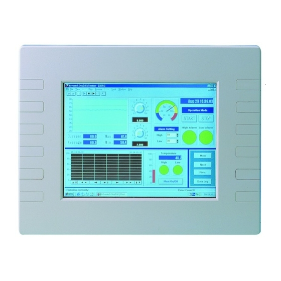
Advantech PPC-A84 User Manual (160 pages)
NS GXm/GX1 processor-based Panel PC with 8.4"/12.1" LCD flat panel display
Brand:
Advantech
| Category:
Touch Panel
| Size: 4 MB
Table of Contents
Copyright Notice
2
Packing List
4
Additional Information and Assistance
5
Safety Instructions
6
Table of Contents
8
Chapter 1 General Information
15
Introduction
16
Specifications
17
General
17
Standard SBC Functions (PCM-5821)
17
LCD Specification
18
PCMCIA Module (Optional)
20
Environmental Specifications
20
Front View
21
Power Indicator
21
Figure 1-1: Front View of the PPC-A84
21
Dimensions
22
Figure 1-2A: Dimensions of the PPC-A84
22
Figure 1-2B: Dimensions of the PPC-A120
22
Cutout Dimensions(Suggestion)
23
Figure 1-3A: Dimensions of Cutout and Panel Mounting Holes (A84)
23
Figure 1-3B: Dimensions of Cutout and Panel Mounting Holes (A120)
23
Panel Mounting
24
Figure1-4: Panel Mounting
24
Universal Mounting Arm (Optional)
25
Figure 1-5: Mounting with Universal Arm ( I )
25
Figure1-6: Mounting with Universal Arm (II)
26
Figure1-7: Mounting with Universal Arm (III)
26
Important Notice
27
Chapter 2 System Setup
29
A Quick Tour of the Panel PC
30
Figure 2-1: Front View of the PPC-A84
30
Figure 2-2: Top Side View of the PPC-A84
31
Figure 2-3: Rear View of the PPC-A84
32
Figure 2-4: I/O Section of the PPC-A84/A120
33
Figure 2-5: Install or Remove the Power Supply,Hdd Drive,And PCMCIA Module (A84)
34
Preparing for First-Time Usage
35
Installation Procedures
35
Connecting the Power Inlet Cable (180 CM)
35
Connecting the Insulator to Your Power Sources
36
Installing a Primary 2.5" HDD (Plug-In)
39
Installing DRAM (SODIMM)
39
Installing I/O Equipment
41
Installing One External IDE (3.5" HDD/CD-ROM) Device and an External FDD
41
PS/2 Keyboard and PS/2 Mouse
42
MIC-In, Line-In, Speaker out
42
External VGA
43
Two Serial COM Ports
43
USB Ports
43
Parallel Port
44
Ethernet
44
How to Install Software to the HDD
45
Method 1: Use the Ethernet
45
Method 3: Use the COM or Parallel Port
45
Method 4: Use a 3.5" HDD or CD-ROM
45
Running the BIOS Setup Program
46
Installing System Software
46
Installing the Drivers
47
(Pcm-5821)
49
Chapter 3 The Engine of the PPC-A84/A120-X5X
50
Introduction
50
Features
51
Jumpers and Connectors
52
Setting Jumpers
52
Jumpers
53
Table 3-1: Jumpers and Their Functions
53
Connectors
54
Table 3-2: Panel PC Connectors
54
Figure 3-1: Locating Jumpers and Connectors on PCM-5821 (Front Side)
55
Figure 3-2: Locating Jumpers and Connectors PCM-5821 (Rear Side)
56
Table 3-3: Wake-On LAN Selection (JP1)
57
Wake on LAN Selection (Reserved) (JP1)
57
CMOS Clear (JP2)
57
Watchdog Timer Configuration
57
Table3-4: Clear Cmos/External RTC (JP2)
57
Table 3-6: COM2 RS-232/422/485 Setting (JP3, JP4)
58
Table3-5: Watchdog Activity Selection (JP2)
58
Watchdog Activity Selection (JP2)
58
COM2 RS-232/422/485 Setting (JP3, JP4,JP5)
58
Table 3-8: Buzzer Enable (JP10)
59
Buzzer Enable (JP10)
59
Table 3-7: COM2 RS-232/422/485 Setting (JP5)
59
Chapter 4 PCI Bus Ethernet Interface
61
Introduction
62
Installation of Ethernet Driver
62
Installation for WINDOWS 95
63
Installation for WINDOWS 98
67
Installation for WINDOWS NT
68
Further Information
73
Chapter 5 PCI SVGA Setup
75
Introduction
76
Chipset
76
Display Memory
76
Display Types
76
Installation of SVGA Driver
76
Installation for Windows 95
78
Installation for WINDOWS 98
82
Installation for WINDOWS NT
85
Further Information
87
Chapter 6 Touchscreen
89
Introduction
90
Installation of Touch Screen Driver for the PPC-A84
90
Installation for MS-DOS
91
Installation for Windows 95
92
Installation for Windows 98
94
Installation for Windows NT
96
Installation for Touch Screen Driver for the PPC-A120
98
Installation for Windows 95
99
Installation for Windows 98
101
Installation for Windows NT
103
Chapter 7 Audio Setup
107
Introduction
108
Installation of Audio Driver
108
Installation for Windows 95
109
Installation for WINDOWS NT
112
Installation for Windows 98
112
Further Information
115
Chapter 8 Award BIOS Setup
117
Award BIOS Setup
118
CMOS Setup Utility
118
Figure 8-1: Setup Program Initial Screen
118
Standard CMOS Setup
119
Figure 8-2: CMOS Setup Screen
119
Hard Disk Configurations
120
BIOS Features Setup
121
Figure 8-3: BIOS Features Setup Screen
121
Chipset Features Setup
124
Figure 8-4: Chipset Features Setup Screen
124
Power Management Setup
125
Figure 8-5: Power Management Setup Screen
125
PNP/PCI Configuration Setup
127
Figure 8-6: PNP/PCI Configuration Setup Screen
127
Load BIOS Defaults
128
Figure 8-7: Load BIOS Defaults Screen
128
Load Setup Defaults
129
Integrated Peripherals
129
Figure 8-8: Integrated Peripherals Screen
129
WDT Active When Power on
131
Password Setting
132
IDE HDD Auto Detection
132
Save and Exit Setup
133
Exit Without Saving
133
Figure 8-9: Save and Exit Setup Screen
133
Appendix A Programming the Watchdog Timer
135
Programming the Watchdog Timer
136
Appendix B Full Disassembly Procedures
139
Full Disassembly Procedures
140
Figure B-1: Disassembly Steps 1 - 4
141
Figure B-2: Disassembly Steps 5 - 7
143
Figure B-3: Disassembly Steps 8 - 12
145
Appendix C Pin Assignments
147
Inverter Power Connector (J1)
148
Flat Panel Display Connector (J2)
148
Primary IDE Connector (J3)
149
Keyboard Connector (J4)
150
Internal Touchscreen Connector(J5)
151
Comapctflash™ Disk Secondary IDE Connector (CN2)
152
Table C-6: Compactflash™ Disk Secondary IDE Connector (CN2)
152
CD in (Cn3)
153
Power Fan Power Connector (CN4)
153
External KBT2 Connector (CN7)
153
Table C-9: CPU Fan Power Connector (CN7)
153
Table C-7: CD in (CN3)
153
CPU Fan Power Connector (CN8)
154
Power Switch Connector (CN10)
154
Speaker and Microphone Connector (CN20)
155
Power Test Connector (PS1)
155
Com2
156
Table C-15: External IDE Connector
157
External IDE Connector
157
External Floopy Drive Connector
158
Table C-16: External Floppy Drive Connector
158
Table C-17: External FDD and HDD Power Connector
159
External FDD and HDD Power Connector
159
System I/O Ports
159
Advertisement
Advantech PPC-A84 User Manual (146 pages)
NS GXm Processor-Based Panel PC with 8.4" LCD Flat Panel Display
Brand:
Advantech
| Category:
Touch Panel
| Size: 4 MB
Table of Contents
Copyright Notice
2
Packing List
4
Safety Instructions
6
Table of Contents
8
Chapter 1 General Information
15
Introduction
16
Specifications
17
General
17
Standard SBC Functions (PCM-5821)
17
LCD Specification
18
DC Input Power Supply Module (12Volt or 24Volt)
19
PCMCIA Module (Optional)
20
Environmental Specifications
20
Front View
21
Figure 1-1: Front View of the PPC-A84
21
Dimensions
22
Figure 1-2: Dimensions of the PPC-A84
22
Cutout Dimensions(Suggestion)
23
Figure 1-3: Dimensions of Cutout and Panel Mounting Holes
23
Panel Mounting
24
Figure1-4: Panel Mounting
24
Universal Mounting Arm (Optional)
25
Figure 1-5: Mounting with Universal Arm (I)
25
Figure1-6: Mounting with Universal Arm (II)
26
Figure1-7: Mounting with Universal Arm (III)
26
Chapter 2 System Setup
27
A Quick Tour of the Panel PC
28
Figure 2-1: Front View of the Panel PC
28
Figure 2-2: Top Side View of the Panel PC
29
Figure 2-3: Rear View of the Panel PC
30
Figure 2-4: I/O Section of the Panel PC
31
Figure 2-5: Install or Remove the Power Supply,Hdd Drive,Pcacia Module
32
Preparing for First-Time Usage
33
Installation Procedures
33
Connecting the Power Inlet Cable (180 CM)
33
Connecting the Insulator to Your Power Sources
34
Installing a Primary 2.5" HDD (Plug-In)
37
Installing DRAM (SODIMM)
38
Installing I/O Equipment
39
Installing One External IDE (3.5" HDD/CD-ROM) Device and an External FDD
39
PS/2 Keyboard and PS/2 Mouse
40
MIC-In, Line-In, Speaker out
40
External VGA
41
Two Serial COM Ports
41
USB Ports
41
Parallel Port
42
Ethernet
42
How to Install Software to the HDD
43
Method 1: Use the Ethernet
43
Method 2: Use a FDD
43
Method 3: Use the COM or Parallel Port
43
Method 4: Use a 3.5" HDD or CD-ROM
43
Running the BIOS Setup Program
44
Installing System Software
44
Installing the Drivers
45
Chapter 3 The Engine of PPC-A84 (PCM-5821)
47
Introduction
48
Features
49
Jumpers and Connectors
50
Setting Jumpers
50
Jumpers
51
Table 3-1: Jumpers and Their Functions
51
Connectors
52
Table 3-2: Panel PC Connectors
52
Locating Jumpers and Connectors
53
Figure 3-1: Locating Jumpers and Connectors PCM-5821 (Front Side)
53
Figure 3-2: Locating Jumpers and Connectors PCM-5821 (Rear Side)
54
Wake on LAN Selection (Reserved) (JP1)
55
CMOS Clear (JP2)
55
Watchdog Timer Configuration
55
Table 3-3: Wake-On LAN Selection (JP1)
55
Table3-4: Clear Cmos/External RTC (JP2)
55
1Watchdog Activity Selection (JP2)
56
COM2 RS-232/422/485 Setting (JP3, JP4,JP5)
56
Table3-5: Watchdog Activity Selection (JP2)
56
Table 3-6: COM2 RS-232/422/485 Setting (JP3, JP4)
56
Table 3-7: COM2 RS-232/422/485 Setting (JP5)
56
Buzzer Enable (JP10)
57
Table 3-8: Buzzer Enable (JP10)
57
Chapter 4 PCI Bus Ethernet Interface
59
Introduction
60
Installation of Ethernet Driver
60
Installation for WINDOWS 95
61
Installation for WINDOWS 98
64
Installation for WINDOWS NT
67
Further Information
69
Chapter 5 PCI SVGA Setup
71
Introduction
72
Chipset
72
Display Memory
72
Display Types
72
Installation of SVGA Driver
72
Installation for Windows 95
74
Installation for WINDOWS 98
76
Installation for WINDOWS NT
78
Further Information
80
Chapter 6 Touchscreen
81
Introduction
82
General Information
82
Specifications
82
Installation of Touchscreen Driver
82
Installation for MS-DOS
83
Installation for WINDOWS 95
84
Installation for WINDOWS 98
86
Installation for WINDOWS NT
88
Chapter 7 Audio Setup
91
Introduction
92
Installation of Audio Driver
92
Installation for Windows 95
93
Installation for WINDOWS 98
96
Installation for WINDOWS NT
98
Further Information
100
Chapter 8 Award BIOS Setup
101
Award BIOS Setup
102
CMOS Setup Utility
102
Figure 8-1: Setup Program Initial Screen
102
Standard CMOS Setup
103
Figure 8-2: CMOS Setup Screen
103
Hard Disk Configurations
104
BIOS Features Setup
105
Figure 8-3: BIOS Features Setup Screen
105
Chipset Features Setup
108
Figure 8-4: Chipset Features Setup Screen
108
Power Management Setup
109
Figure 8-5: Power Management Setup Screen
109
PNP/PCI Configuration Setup
111
Figure 8-6: PNP/PCI Configuration Setup Screen
111
Load BIOS Defaults
112
Figure 8-7: Load BIOS Defaults Screen
112
Load Setup Defaults
113
Integrated Peripherals
113
Figure 8-8: Integrated Peripherals Screen
113
Password Setting
116
IDE HDD Auto Detection
116
Save and Exit Setup
117
Exit Without Saving
117
Figure 8-9: Save and Exit Setup Screen
117
Appendix A Programming the Watchdog Timer
119
Programming the Watchdog Timer
120
Appendix B Full Disassembly Procedures
123
Full Disassembly Procedures
124
Figure B-1: Disassembly Steps 1 - 4
125
Figure B-2: Disassembly Steps 5 - 7
127
Figure B-3: Disassembly Steps 8 - 12
129
Appendix C Pin Assignments
131
Inverter Power Connector (J1)
132
Flat Panel Display Connector (J2)
132
Table C-1: Inverter Power Connector (J1)
132
Table C-2: Flat Panel Display Connector (J2)
132
Primary IDE Connector (J3)
133
Table C-3: Primary IDE Connector (J3)
133
Keyboard Connector (J4)
134
Table C-4: Keyboard Connector (J4)
134
Internal Touchscreen Connector(J5)
135
Table C-5: Internal Touchscreen Connector (J5)
135
Comapctflash™ Disk Secondary IDE Connector (CN2)
136
Table C-6: Compactflash™ Disk Secondary IDE Connector (CN2)
136
CD in (Cn3)
137
Power Fan Power Connector (CN4)
137
Table C-7: CD in (CN3)
137
Table C-8: Power Fan Power Connector (CN6)
137
External KBT2 Connector (CN7)
138
Table C-10: CPU Fan Power Connector (FAN1)
138
Table C-9: CPU Fan Power Connector (CN7)
138
CPU Fan Power Connector (CN8)
138
Power Switch Connector (CN10)
139
Speaker and Microphone Connector (CN20)
139
Table C-11: Power Switch Connector (CN10)
139
Table C-12: Speaker and Microphone Connector (CN20)
139
Power Test Connector (PS1)
140
Table C-13: Power Test Connector (PS1)
140
Com2
141
Table C-14: COM2
141
External IDE Connector
142
Table C-15: External IDE Connector
142
External Floopy Drive Connector
143
Table C-16: External Floppy Drive Connector
143
External FDD and HDD Power Connector
144
System I/O Ports
144
Table C-17: External FDD and HDD Power Connector
144
Table C-18: System I/O Ports
144
Advertisement
Related Products
Advantech PPC-A84/A120-X5X
Advantech PPC-150 Series
Advantech PPC-3180SW-PN4A
Advantech PPC-310-PJ60A
Advantech PPC-115W-PK92DB
Advantech PPC-415W
Advantech PPC-317S
Advantech PPC-310W EHL
Advantech PPC-312-RJ60A
Advantech PPC-3181SW
Advantech Categories
Motherboard
Computer Hardware
Desktop
Touch Panel
Network Router
More Advantech Manuals
Login
Sign In
OR
Sign in with Facebook
Sign in with Google
Upload manual
Upload from disk
Upload from URL