Table of Contents
Advertisement
Quick Links
Instruction Manual
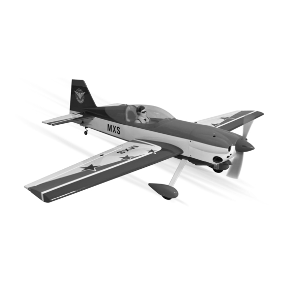
GP/EP size.120 SCALE 1:4 ½ ARF
SPECIFICATION
- Wingspan: 1651mm (65 in)
- Length: 1616mm (63.6 in)
- Flying weight: 4700-5200 gr
- Wing area: 56 dm2
- Wing loading: 85g/dm2
- Wing type: Naca airfoils
- Covering type: Genuine ORACOVER®
- Gear type: Aluminum Hi-grade for main gear
and spring wire for tail gear (included)
- Spinner size: Plastic 70mm (included)
- Radio: 4 channel minimum (not included)
- Servo: 6 standard hitorque servo: 2 aileron;
2 elevator; 1 rudder; 1 throttle (not included)
- Recommended receiver battery:
4.8-6V / 1200-2000mAh NiMH (not included)
- Servo mount: 21mm x 42 mm
- Propeller: suit with your engine
- Engine: .120 / 2-stroke or .120/4-stroke glow
engine (not included)
- Motor: brushless outrunner 2000-2400 W,
450 KV (not included)
- Gravity CG: 115 mm (4.5in) Back from the
leading edge of the wing, at the fuselage
- Control throw Ailerons: Low: 9mm up/down,
10% expo; High: 12mm up/down, 10% expo
- Control throw Elevators: Low: 8mm up/down,
12% expo; High: 10mm up/down, 12% expo
- Control throw Rudder: Low: 30mm right/left,
15% expo; High: 45mm right/left, 15% expo
- Experience level: Intermediate
- Plane type: Scale Aerobatic
RECOMMENDED MOTOR AND BATTERY SET UP
- Motor: RIMFIRE .120 (not included)
- Lipo cell: 6-12 cells / 4000 – 5500mAh (not included)
- Esc: 80-100A (not included)
Advertisement
Table of Contents

Related Manuals for Phoenix Model MXS


Summary of Contents for Phoenix Model MXS
- Page 1 Instruction Manual GP/EP size.120 SCALE 1:4 ½ ARF SPECIFICATION - Engine: .120 / 2-stroke or .120/4-stroke glow - Wingspan: 1651mm (65 in) engine (not included) - Length: 1616mm (63.6 in) - Motor: brushless outrunner 2000-2400 W, - Flying weight: 4700-5200 gr 450 KV (not included) - Wing area: 56 dm2 - Gravity CG: 115 mm (4.5in) Back from the...
-
Page 2: Tools And Supplies Needed
INSTALLING THE AILERONS properly before gluing! This will assure proper assembly. The MXS GP/EP size.120 SCALE 1:4 1. Test fit the ailerons to the wing with the hinges. ½ ARF is hand made from natural materials, If the hinges don’t remain centered, stick a pin... -
Page 3: Installing The Control Horns
Instruction Manual MXS size.120 INSTALL THE AILERONS SERVOS & PUSHRODS 1. Install the servo in the wing require the use of one 305mm servo extension for each aileron servo. One Y-harness connector is required and is used to allow the aileron servo to plug into one slot in your receiver. -
Page 4: Installing The Aileron Linkages
Instruction Manual MXS size.120 2. Secure the control horn into the aileron. 1. Locate the pushrod wire. Screw the link ball onto the threaded end of the wire. Tighten the nut against and then install the link ball on the aileron control horn. -
Page 5: Installing The Horizontal Stabilizer
Instruction Manual MXS size.120 2. Remove the covering from the stabilizer. When cutting through the covering to remove it, cut with only enough pressure to only cut through the covering it's self. Cutting into the balsa structure may weaken it. This could lead to possible failure during flight. -
Page 6: Installing The Rudder
Instruction Manual MXS size.120 INSTALLING THE RUDDER 5. When you are sure that everything is aligned correctly, mix up a generous amount of 30 minute epoxy. Apply a thin layer to the bottom Repeat step 1 - step 2 from the installing aileron and to the top of the stabilizer mounting area for the installing rudder. -
Page 7: Installing The Main Landing Gear
Instruction Manual MXS size.120 2. Remove the covering. INSTALLING THE MAIN LANDING GEAR 1. Nuts have been installed at the factory. 2. Install main landing gear into the fuselage using (4) 4mm x 20mm socket head screws and flat washers provided in the kit. -
Page 8: Installing The Engine
Instruction Manual MXS size.120 Trim the wood Install with OS 120 two stroke Collar Collar 4mm collar 4mm axle 8mm screw After installing the wheel pant, apply a small drop of thin C/A to the bottom nut. INSTALLING THE ENGINE... -
Page 9: Installing The Stopper Assembly
Instruction Manual MXS size.120 Battery INSTALLING THE THROTTLE PUSHROD HOUSING 1. Place the engine into the engine mount and align it properly with the front of the cowling. The distance from the firewall to the front of the Screw engine thrust washer should 145mm. -
Page 10: Installing The Throttle Servo
Instruction Manual MXS size.120 4. Carefully bend the third nylon tube down at a 9. To secure the fuel tank in place, apply a bead of 45 degree angle (using a cigarette lighter). This silicon sealer to the forward area of the tank, tube will be vent tube to the fueling valve. -
Page 11: Installing The Rudder Servo
Instruction Manual MXS size.120 . Repeat these step as installing the aileron linkages (Page 4 and page 5). Remove the covering Elavator rod The elevator linkages are assembled as shown below 22mm 22mm 65mm . Repeat these step for the second servo elevator. -
Page 12: Installing The Rudder Linkages
Instruction Manual MXS size.120 INSTALLING THE RUDDER LINKAGES The rudder is controlled by two metal cables. Aluminum ball Crimp Cable Install the rudder linkages and cables as below. 1. Use a hobby knife to remove the covering from the openings for the rudder control cables. -
Page 13: Mounting The Cowl
Instruction Manual MXS size.120 MOUNTING THE COWL 1. Remove the muffler and needle valve assembly from the engine. Slide the fiberglass cowl over the engine. M3 Clevis 2. Measure and mark the locations to be cut out for engine head clearance, needle valve, muffler. -
Page 14: Final Assembly
Instruction Manual MXS size.120 Switch Zip tie Receiver Battery FINAL ASSEMBLY BALANCING INSTALLING THE SPINNER 1. It is critical that your airplane be balanced correctly. Improper balance will cause your Install the spinner back-plate, propeller and plane to lose control and crash. -
Page 15: Control Throws
Instruction Manual MXS size.120 CONTROL THROWS 1. We highly recommend setting up a plane using the control throws listed. Aileron Control 2. The control throws should be measured at the widest point of each control surface. 3. Check to be sure the control surfaces move in the correct directions. - Page 16 I/C FLIGHT GUIDELINES Operate the control sticks on the When ready to fly, first extend the transmitter and check that the control transmitter aerial. surfaces move freely and in the ALWAYS land the model INTO the CORRECT directions. wind, this ensures that the model lands at the slowest possible speed.
Need help?
Do you have a question about the MXS and is the answer not in the manual?
Questions and answers