Phoenix Model F4U CORSAIR Instruction Manual
Phoenix model f4u corsair scale 1:8 ½ arf .46-.55 model aircraft
Hide thumbs
Also See for F4U CORSAIR:
- Instruction manual (17 pages) ,
- Instruction manual (21 pages) ,
- Instruction manual (52 pages)
Table of Contents
Advertisement
Quick Links
I n s t r u c t i o n M a n u a l
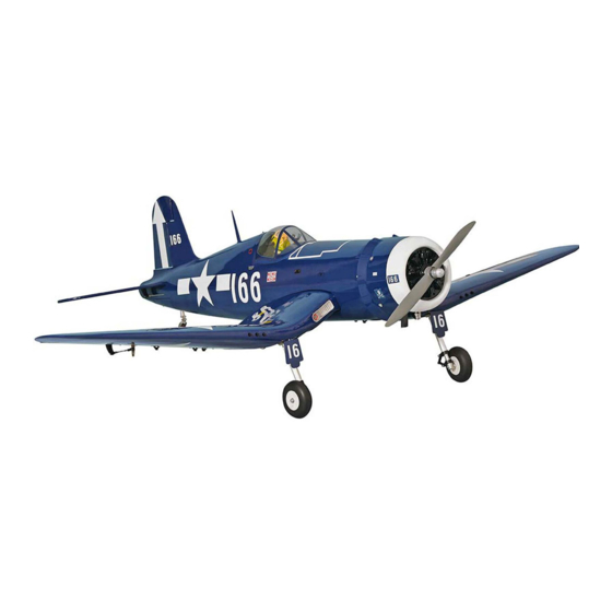
F4U CORSAIR
SCALE 1:8 ½ ARF .46-.55
SPECIFCATION
- Wingspan: 1485mm (58.5in)
- Length: 1127mm (44.5 in)
- Flying weight: 3000-3300gr
- Wing area: 38.2 dm2
- Wing loading: 75g/dm2
- Wing type: Naca airfoils
- Covering type: Genuine ORACOVER®
- Gear type: Mechanic rotary 90 degree
retract and spring suspension gear (included)
- Spinner size: corsair style (not included)
- Radio: 6 channel minimum (not included)
- Servo: 5 standard servo: 2 aileron; 1 elevator;
1 rudder; 1 throttle; 2 servo retract futaba
S3170G (not included)
- Recommended receiver battery:
4.8-6V / 800-1200mAh NiMH (not included)
- Servo mount: 21mm x 42 mm
- Propeller: suit with your engine
- Engine: .46-.55 / 2-stroke or .52/4-stroke
glow engine (not included)
- Motor: brushless outrunner 1000-1400 W,
480 KV (not included)
- Gravity CG: 85 mm (3.3 in) Back from the
leading edge of the wing, at the fuselage
- Control throw Ailerons: Low: 8mm up/down,
10% expo; High: 10mm up/down, 10% expo
- Control throw Elevators: Low: 8mm up/down,
12% expo; High: 10mm up/down, 12% expo
- Control throw Rudder: Low: 25mm right/left,
15% expo; High: 30mm right/left, 15% expo
- Experience level: Intermediate
- Plane type: Scale Military
RECOMMENDED MOTOR AND BATTERY SET UP
- Motor: RIMFIRE .46-.55 (not included)
- Lipo cell: 6 cells / 4000 – 5500mAh (not included)
- Esc: 50-80A (not included)
Advertisement
Table of Contents

Related Manuals for Phoenix Model F4U CORSAIR


Summary of Contents for Phoenix Model F4U CORSAIR
- Page 1 I n s t r u c t i o n M a n u a l F4U CORSAIR SCALE 1:8 ½ ARF .46-.55 SPECIFCATION - Wingspan: 1485mm (58.5in) - Engine: .46-.55 / 2-stroke or .52/4-stroke - Length: 1127mm (44.5 in)
-
Page 2: Tools And Supplies Needed
This will assure proper 1. Test fit the ailerons to the wing with the hinges. assembly. F4U CORSAIR SCALE 1:8 ½ ARF If the hinges don’t remain centered, stick a pin .46-.55 is hand made from natural materials,... -
Page 3: Installing The Aileron Servos
Instruction Manual F4U CORSAIR INSTALLING THE AILERON SERVOS 5. Place the aileron servo tray / hatch into the servo box on the bottom of the wing and drill 1. Install the rubber grommets and brass eyelets pilot holes through the tray and the servo box onto the aileron servo. -
Page 4: Installing The Aileron Linkages
Instruction Manual F4U CORSAIR 3. Repeat step # 1 - # 2 to install the control horn on the opposite aileron. RIGHT WRONG Silicone Tube INSTALLING THE AILERON LINKAGES 1. Working with the aileron linkage for now, thread one nylon clevis at least 14 turns onto one of the 2mm x 180mm threaded wires. - Page 5 Instruction Manual F4U CORSAIR 5. Secure the retract to the wing. Trim the plastic 2. Glue the plastic part by C.A glue. 6. Secure the wheel. C.A glue Servo retract Screw 3. Install the servo retract gear. 7. Secure the axle.
-
Page 6: Installing The Horizontal Stabilizer
Instruction Manual F4U CORSAIR Make the same way for the second retract landing gear. Connector 5. Remove the stabilizer. Using the lines you just drew as a guide, carefully remove the covering from between them using a modeling knife. INSTALLING THE HORIZONTAL STABILIZER... -
Page 7: Tail Gear Installation
Instruction Manual F4U CORSAIR 2. Secure the wheel. 7. When you are sure that everything is aligned correctly, mix up a generous amount of 30 Collar minute epoxy. Apply a thin layer to the bottom of the stabilizer mounting area and to the stabilizer mounting platform sides in the fuselage. -
Page 8: Engine Installation
Instruction Manual F4U CORSAIR 5. Bend “ L ” the tail gear. 9. Secure the tail gear using the collar retainer. Bend “ L ” 22mm Collar retainer ENGINE INSTALLATION 6. Cut away the tail gear. INSTALLING THE THROTTLE PUSHROD HOUSING 25mm 1. -
Page 9: Installing The Engine
Instruction Manual F4U CORSAIR If your engine is equipped with a remote needle valve, we suggest installing it into the engine at this time. 3. Slide the pushrod housing through the hole in the firewall, through the hole in the forward bulkhead, and into the servo compartment. - Page 10 Instruction Manual F4U CORSAIR 5. Test fit the stopper assembly into the tank. It may be necessary to remove some of the flashing around the tank opening using a modeling knife. If flashing is present, make Battery sure none of it falls into the tank.
-
Page 11: Installing The Elevator Pushrod
Instruction Manual F4U CORSAIR SERVO INSTALLATION INSTALLING THE FUSELAGE SERVOS 1. Install the rubber grommets and brass collets into the elevator, rudder and throttle servos. Test fit the servos into the servo tray. Trim the tray if necessary to fit your servos. -
Page 12: Installing The Rudder Pushrod
Instruction Manual F4U CORSAIR 5. The control horn should be mounted on the left 10. Plug the elevator servo into the receiver and side of the rudder at the leading edge, in line center the servo. Install the servo arm onto the with the rudder pushrod. -
Page 13: Mounting The Cowl
Instruction Manual F4U CORSAIR MOUNTING THE COWL 1. Remove the muffler and needle valve assembly from the engine. Slide the fiberglass cowl over the engine. 2. Measure and mark the locations to be cut out for engine head clearance, needle valve, muffler,. - Page 14 Instruction Manual F4U CORSAIR Glue with epoxy Screw BALANCING Screw 1. It is critical that your airplane be balanced correctly. Improper balance will cause your plane to lose control and crash. THE CENTER OF GRAVITY IS LOCATED 85mm BACK FROM THE LEADING EDGE OF THE WING, AT THE FUSELAGE.
-
Page 15: Lateral Balance
Instruction Manual F4U CORSAIR LATERAL BALANCE After you have balanced a plane on the C.G. You should laterally balance it. Doing this will help the airplane track straighter. 5. Turn the airplane upside down. Attach one loop of heavy string to the engine crankshaft and one to the tail wheel wire. - Page 16 I/C FLIGHT GUIDELINES Operate the control sticks on the When ready to fly, first extend the transmitter and check that the control transmitter aerial. surfaces move freely and in the ALWAYS land the model INTO the CORRECT directions. wind, this ensures that the model lands at the slowest possible speed.
Need help?
Do you have a question about the F4U CORSAIR and is the answer not in the manual?
Questions and answers