Table of Contents
Advertisement
Advertisement
Table of Contents

Summary of Contents for ESP Enterview 5
- Page 1 VIDEO DOOR ENTRY SYSTEM INSTRUCTIONS...
-
Page 2: Table Of Contents
Enterview 5 Overview ........ -
Page 3: Enterview 5 Overview
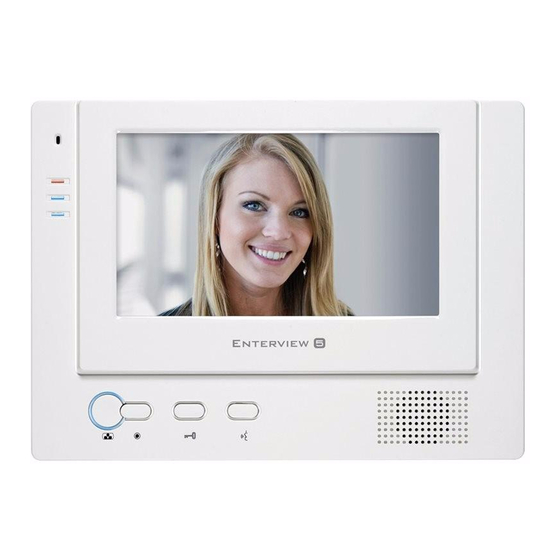
Enterview 5 Overview 4 Handsets maximum per-system 2 Audio-Only handsets maximum per-system Each handset requires supplied PSU (1 PSU per handset required) Keypad Camera requires suppIied PSU Standard Camera requires EVBPS for door release facility For a voltage-free contact: Keypad Camera requires a12VDC relay (not supplied) -
Page 4: Wiring Configuration
AC240 AC240 Wiring Configuration Handset PSUs Standard Camera provided LOCK AC240 AC240 Keypad Camera See additional wiring instructions for Keypad Handset PSUs provided LOCK AC240 Keypad PSU provided... -
Page 5: Door Wiring Configuration
AC240 AC240 2 Door Wiring Configuration Handset PSUs provided LOCK AC240 LOCK See additional wiring instructions for keypad Handset Connections Keypad PSU provided AC240 NOTE: J1 AND J2 – DO NOT REMOVE J3 – ONLY REMOVE FOR MULTIWAY OUTDOOR STATION CONNECTION... -
Page 6: Maximum Wiring Configuration
Maximum Wiring Configuration... -
Page 7: Additional Keypad And Magnetic Lock Wiring
Additional Keypad and Magnetic Lock Wiring EMERGENCY – BREAK GLASS MAGLOCK Back of Keypad camera AC240 Keypad PSU provided EXIT BUTTON *For a voltage-free contact: Keypad requires and additional 12VDC relay (not supplied) Additional Keypad and Yale-release Wiring – Back of Keypad camera Yale Release AC240 Keypad PSU provided... -
Page 8: Keypad Commands
Keypad Commands Default master code: 1234 Entering Programming mode 1 Press * then 4 digit master code 2 If successful three tones will sound and the LED will flash Adding user codes 1 Enter programming mode 2 lnput the code group O1-31 for normal operation, 32-40 for latching mode. 3 Enter the 4 digit code, if successful three tones sound if not 2 tones sound. -
Page 9: Installation Guide
Installation Guide EVH5 EVH5C EVH5C-HF / EVHF10W / EVHF10B... - Page 10 Installation Guide EV5 CAM EV5 CCAM EV5KPCAM EV5CKPCAM *Recommended installation height 150cm...
-
Page 11: Trouble Shooting Guide
Trouble Shooting Guide No picture appears on the monitor (blue or white screen) Check that all wires are connected and connected in the correct configuration Check that the voltage at the back of the monitor across terminals 5 and 6. The voltage should be over 14.3vDC, if it is not then the handset will not function correctly One or more monitors are not working but others are Check that all wires are connected and connected in the correct configuration... -
Page 12: Technical Specification
Technical Speci cation Enterview 5 Enterview 5 CAM Power 14.5 DC Power 14.5 DC Video Output 1-1VP-P 750hm B/W PAL Video Output 1-1VP-P 750hm B/W PAL Operating Temp. -10/55ºC Min. Illumination 1 Lux Consumption 800ma Operating Temp. -10/55ºC Dimensions (mm)


Need help?
Do you have a question about the Enterview 5 and is the answer not in the manual?
Questions and answers