Advertisement
Table of Contents
- 1 Table of Contents
- 2 Planning and Installing the Enterview MX
- 3 Fitting and Wiring the External Call Station
- 4 Wiring Diagram
- 5 External Call Station Internal Wiring Connections
- 6 Trade Button
- 7 Fitting and Wiring the Handset
- 8 System Schematic Wiring Diagram
- 9 Programming the Keypad
- 10 Programming the Proximity Reader
- 11 Trouble Shooting Guide
- Download this manual
Advertisement
Table of Contents

Related Manuals for ESP Enterview MX EVMX2


Summary of Contents for ESP Enterview MX EVMX2
-
Page 2: Table Of Contents
Table of contents Planning and installing the Enterview MX ......3 Fitting and wiring the external call station ......4 External call station internal wiring connections . -
Page 3: Planning And Installing The Enterview Mx
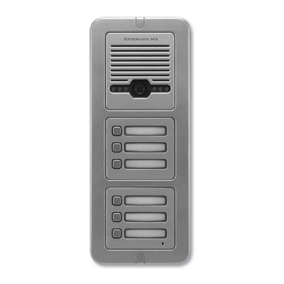
Planning and installing the Enterview MX Planning your MX Door Entry System External call station How many Entry Doors (Front or/and Rear) Audio only or with Video Monochrome/ colour Integral Key pad Mounting Flush or surface Integral Proximity Reader External Call buttons (one per dwelling) Trade entry control Combined timed Lock and outdoor call station power supply (EVBPS) Note: The maximum cable distance per external call button to each handset is 100... -
Page 4: Fitting And Wiring The External Call Station
Basic cabling 240 VAC mains feed to external door and lock control power supply (EVBPS) 240 VAC mains feed to each handset (via transformer- supplied) 4 core from each external call station (front/rear) to its own power supply (EVBPS) CAT5e from each external call station (front/rear) to each handset 4 core from push to exit button to EVBPS (power supply) 4 core from lock to EVBPS (power supply) 4 core from EVBPS (power supply) to emergency break glass (if fitted) - Page 5 Fig. 2 Wiring the external call station Each call button will have its own brown 4 core connector (supplied) consisting of red, blue, yellow and white cores. The 4 colours that are connected to the brown connector are to be connected to the corresponding 4 core cable going to each of the apartments.
-
Page 6: External Call Station Internal Wiring Connections
Wiring diagram Main panel Main panel with keypad Main panel with proximity with 6 buttons and 3 buttons reader and 3 buttons S eal S eal S eal Black and Red wire connect to Connect Connect 12 volt DC to power. -
Page 7: Trade Button
Trade Button Trade button release module. Trade Button Module Front View Trade Button Back View White plug connector 12vDC Input for additional modules (From EV-BPS) 2 Button Version 3 Button Version CN1- Trade button output (volt-free) CN2 & CN3 -Connection for monitor Trade Button Fig. -
Page 8: Fitting And Wiring The Handset
Assembly of the external call station Once all connections have been made and all plugs Screws inserted into the appropriate sockets fit the rubber seal to the cover of the call station see Fig. 5. Use the two supplied screws to secure the front cover to the back plate, paying attention to the seal so it remains seated correctly Fitting and wiring the handset... -
Page 9: System Schematic Wiring Diagram
System schematic wiring diagram Main handset Main handset Extension handset ACDC adaptor included ACDC adaptor included ACDC adaptor included Main handset Main handset Extension handset ACDC adaptor included ACDC adaptor included ACDC adaptor included Door Release 240vAC INPUT Outdoor Panel EVBPS... -
Page 10: Programming The Keypad
Fitting the handset to the metal back plate Locate the 4 lugs on the metal back plate, one located on each corner see Fig. 11, these lugs must fit into the recesses on the rear of the hand set. Place the handset over the metal back plate keeping the Lugs cables flat and out of the way... - Page 11 Deleting a user codes from an unknown location Enter programming mode. Press the # key, the blue LED remains on. Enter the 4 digit user code to search and delete, a 2 second confirmation tone will be heard. Return to the beginning to search and delete more lost codes or press the * key to exit programming mode.
-
Page 12: Programming The Proximity Reader
Programming the Proximity Reader All system programming requires the MX remote control. System programming cannot be performed without it. To enter programming mode press * # followed by the 4 digit programing code (The factory default programming code: 4567) followed by #, the indication light on the reader will change from red to amber and a long single confirmation tone will be heard. - Page 13 Deleting User Cards/Tags by swiping Enter programming mode. Press 2 - a single confirmation tone will be heard Swipe the new card/tag to be deleted, a double confirmation tone will be heard. To delete further cards simply swipe the next card/tag. If the error tone is emitted (4x beeps), this indicates that this card/tag is already deleted Press the ** key to exit programming mode.
-
Page 14: Trouble Shooting Guide
Trouble Shooting Guide No picture appears on the monitor (blue or white screen) Check that all wires are connected and connected in the correct configuration Check that the voltage at the back of the monitor across terminals 5 and 6. The voltage should be over 14.3vDC, if it is not then the handset will not function correctly One or more monitors are not working but others are Check that all wires are connected and connected in the correct configuration... - Page 16 Elite Security Products Unit 7, Target Park, Shawbank Rd Telephone: 01527 515150 Lakeside, Redditch B98 8YN email: info@espuk.com...
Need help?
Do you have a question about the Enterview MX EVMX2 and is the answer not in the manual?
Questions and answers