Advertisement
Quick Links
Advertisement

Related Manuals for Extreme Flight VANQUISH MKII


Summary of Contents for Extreme Flight VANQUISH MKII
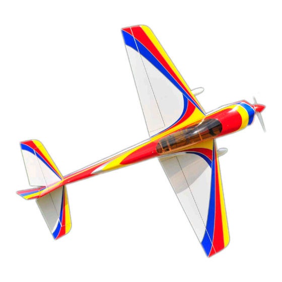
- Page 1 VANQUISH MKII ELECTRIC ARF Instruction Manual ©Copyright 2010 EXTREME FLIGHT RC, Ltd.
- Page 2 Sport flyers fear not! With reduced rates the Vanquish MKII is a very easy plane to fly. Its super light wing loading allows it to land at a walk. It will instill confidence and allow you to improve your flying skills.
- Page 3 You may need to secure the edges of the decal with masking tape to prevent them from rolling up until the solution has dried and evaporated. PLEASE NOTE-The assembly process for the Vanquish MKII is virtually identical to that of the original Vanquish. Most of the pictures in this manual are of the original airframe.
-
Page 4: Wing Assembly
Wing assembly 1. Locate a wing panel. Check to see that all hinges are centered between the wing and aileron. Hold the aileron fully deflected and apply a drop of thin CA to each hinge. Flip the wing over and repeat. 2. - Page 5 3. Locate the composite aileron control horn, aileron pushrod, EZ connector, ball link, 2mm bolt, nut and washer. Remove the covering over the mounting hole for the control horn with your #11 blade. Scuff the part of the control horn that will glue into the aileron slot with fine sandpaper.
-
Page 6: Fuselage Assembly
Fuselage Assembly 5. Let’s mount the landing gear first. Locate the carbon fiber landing gear, (4) 3mm machine screws, (2) park flyer axles, (2) nylon insert lock nuts, (2) wheel collars, (2) wheel pants, (2) wheels 6. Place the wheel on the axle followed by the wheel collar. Slide the wheel pant over the axle with the retention ring inside the wheel pant. - Page 7 8. Attach the radial mount to your motor and install the bolt on prop adapter. Use the included 3mm socket head cap screws and washers to install the motor onto the front of the motor box. Make sure to apply CA to all joints on both sides of the F1 former as well as all joints in the motor box.
- Page 8 12. Slide the elevator onto the hinges in the horizontal stab and glue in place with thin CA. Make sure the elevator is fully deflected when you apply the CA to insure maximum travel is achievable. 13. Slide the rudder onto the hinges in the vertical stabilizer and secure with thin CA. 14.
- Page 9 15. Locate the elevator control horn. Use a sharp hobby knife to remove the covering from the elevator horn slot. 16. Glue the elevator horn in place with medium CA or epoxy. Make sure to scuff the surface of the control horn before gluing. 17.
- Page 10 18. Place an ez-connector on the servo arm. Locate the elevator pushrod and thread a ball link onto the pushrod. Electronically center the servo. Use the 2mm bolt and nut to connect the ball link end of the pushrod to the elevator control horn. Tighten the set screw in the ez connector to clamp down on the pushrod, while making sure the elevator is in the neutral position.
- Page 11 We recommend using the 52mm Extreme Flight spinner for the Vanquish View the cowl from the front, top and sides and when satisfied with the position, secure the cowl with masking tape.
- Page 12 Tighten until snug. 24. The battery should mount right in front of the receiver. Adjust the location of the battery to achieve proper CG. This concludes the assembly of the Vanquish MKII.
- Page 13 Radio Set-up and flight tips. CG range for the Vanquish is from 4.50”- 5.00” from the leading edge of the wing measured at the wing root. Correct CG should be easy to achieve by moving the battery along the length of the battery tray. Adjust to fit your flying style. Control surface recommendations are as follows: Elevator- 10 degrees low rates, 45+ degrees high rates.
Need help?
Do you have a question about the VANQUISH MKII and is the answer not in the manual?
Questions and answers