Advertisement
Quick Links
Advertisement

Related Manuals for Extreme Flight Yak-54


Summary of Contents for Extreme Flight Yak-54
- Page 1 110 inch YAK-54 ARF Instruction Manual ©Copyright 2008 Extreme Flight RC, Ltd.
- Page 2 Extreme Flight RC, Ltd. guarantees this kit to be free of defects in materials and workmanship for a period of 90 days from the date of purchase. All warranty claims must be accompanied by the original dated receipt.
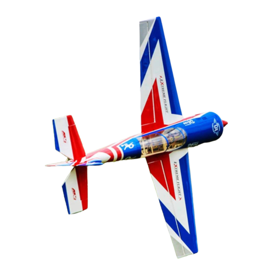
- Page 3 The performance ability of the Extreme Flight RC Yak-54 is phenomenal! With its low weight and enormous control surfaces, the Yak-54 is a 3D monster, capable of all current 3D maneuvers as well as possessing the ability to forge new ground in this exciting new style of flying.
- Page 4 4. DO NOT SKIMP ON SERVOS! The Yak-54 is equipped with very large control surfaces that deflect over 45 degrees. A lot of servo power is required to prevent flutter and to maintain the required deflection for maneuvers.
- Page 5 Hardware Your new Extreme Flight 110 inch Yak includes all necessary hardware with the exception of main wheels, axles and collars. These items were omitted as I have been unable to source satisfactory versions of these items in China. I recommend Dubro 3/16” axles and collars and 4.5 inch main wheels.
- Page 6 Let’s Begin! Elevator Assembly 1. Locate the horizontal stabilizer/elevator assemblies as well as the composite control horns and base pieces from the elevator hardware package. 2. Use a sharp #11 blade to open the 2 slots near the bottom leading edge of the elevator.
- Page 7 3. Insert the 2 control horns into the base plate as shown in the following picture. Carefully insert the control horns into the slots and push down until the base plate is flush with the control surface. You may need to trim the edge of the base plate to prevent it fro overhanging the bevel.
- Page 8 4. Use some denatured alcohol to remove any residue or oils from the composite control horns and base plate. If you wish to paint the control horns for a more finished appearance now is the time to do so. Use some fine sandpaper to roughen the portion of the control horns that will be inserted for gluing.
- Page 9 7. In this step I will outline the procedure we use to install the hinges. There are several ways to do this and several adhesives you can use. We will describe the way we do it, as this method has proven itself over many years of model building.
- Page 10 10. Use a sharp #11 blade to remove the covering from the slot for the elevator servo control horn. You may have to slightly enlarge this hole to allow for maximum travel. This area may have to be lengthened. 11. Before installing the elevator servos, I highly recommend that you temporarily install the servo arms and electronically center the servos.
- Page 11 13. Thread 2 of the heavy duty ball links onto one of the titanium pushrods. Remember that the ends of the pushrods are reverse threaded so that they can be adjusted like a turnbuckle without removing the linkage. Insert a 3mm socket head cap screw into the ball link and into the servo arm.
-
Page 12: Wing Assembly
15. As mentioned previously, you may need to adjust the size of the servo arm exit slot to achieve maximum travel. A ¼” Drum sander in a moto-tool makes quick work of this. Repeat these steps for the other stab/elevator half. Before you set aside the stabs take a moment with your covering iron and go over all of the seams with a medium heat setting, paying special attention to the ends of thin trim stripes. - Page 13 17. Locate the aileron servo holes and remove the covering from these areas. Use a sealing iron to seal the edges of the covering to the insides of the servo opening. Take a few minutes to apply some CA to the joints of the servo rails and the ribs.
- Page 14 19. We will fabricate the linkage much in the same way as the elevator linkage. Aileron control horn length should be 1.50”. As always, use blue Loctite on ALL bolts!
-
Page 15: Rudder Assembly
20. Before beginning the next assembly process, take a few minutes with your sealing iron on a medium heat setting and go over all seams, paying special attention to thin trim stripes and the seam at the leading edge of the wing. If there are wrinkles in the covering on the leading edge sheeting use a heat gun with a 100% cotton t-shirt to remove them and prevent digging into the wood with an iron. -
Page 16: Tail Wheel Assembly
proper position and immediately wipe the excess epoxy from the horns. Carefully check and re-check alignment to insure proper positioning. Use some denatured alcohol and a paper towel to remove any excess epoxy. Re-check the alignment one more time and set the assembly aside to dry. Repeat for the other side of the rudder. - Page 17 metal support bushing and tighten. Now position the rudder tiller in the very center of the rudder’s bottom and about ¼” from the leading edge of the rudder. Mark the hole locations and drill for the supplied wood mounting screws and mount the rudder tiller.
- Page 18 26. Feel along the bottom of the aft bottom fuselage area and you will notice two holes under the covering. Open these holes and position the carbon gear leg over them and mount with the supplied machine bolts. Now locate the springs and mount them within each outer hole of the tillers.
-
Page 19: Fuselage Assembly
Fuselage Assembly 27. We’ll begin by installing the landing gear. Locate the carbon fiber main landing gear. Insert the gear into the slot on the bottom of the fuselage and center it in the slot. Use the pre-drilled holes as guides and drill through the plywood landing gear plate and aluminum mounting bracket. - Page 20 31. Locate the 2 wheel spats and 2 plywood mounting plates. Use sandpaper to scuff the inside of the spat for better glue adhesion. Drill a hole as shown in each ply plate about ¼” below center. This will allow the spat to be positioned slightly higher than center to prevent it from making contact with the ground.
- Page 21 32. Glue the ply mounting plate to the spats as shown with 30 minute epoxy. Once dry drill through the fiberglass spat at the location of the hole in the plywood plate. We chose to use a ½” drill bit for this so that the spat will fit over the hexagon portion of the axle.
- Page 22 34. Next let’s install the engine. We have made this process very easy. The center and offset marks have been scribed into the front of the firewall with a laser.
- Page 23 35. Most manufacturers will provide a mounting template for their engines. If you do not have a template, you can measure the distance between your engine’s mounting holes and determine the center and align with the lines on the firewall. The line to the right of the center line is the proper reference point to use at it provides the proper offset to accommodate for right engine thrust.
- Page 24 easy. Mount the servo in the hole on the bottom of the engine box and use the 2mm pushrod, and white ball link to fabricate the throttle linkage. Cut the pushrod to length, then solder a clevis or threaded rod end (not included) to the servo end. Use the threaded end to connect the ball link to the carburetor.
- Page 25 38. Assemble the included Dubro 32 oz tank. Make sure to use the gas conversion stopper and Tygon tubing for all plumbing. Use nylon cable ties or velcro to secure the tank to the tank tray. The tank should butt up against the wing tube and.
- Page 26 39. Here is where we installed our fuel dot. 40. Once all plumbing is completed and throttle servo and linkage is installed glue the top of the motor box in place with 30 minute epoxy. Alternately you may wish to cut the forward part of the motor box cover away (the part with the laser cut holes to accept the cowl mounting ring) and glue it in place, while attaching the remaining portion of the box top with bolts and blind nuts to allow access to the interior of the motor box.
- Page 27 need to remove covering, measure your pipe and cut the covering where the exhaust tube will exit. The picture below shows two holes, the aft one is where the exhaust will exit, the hole between the gear and the aft hole is to access the pipe’s mounting bracket.
- Page 28 43. Locate the rudder servo tray in the hardware package. Trial fit the tray to the mounting rails, there is a small key in the aft rail. Locate the two pieces of balsa tri-stock, cut 4 pieces the width of the tray and glue these to the rails. This will provide extra gluing surface for the tray.
- Page 29 46. Assemble one end of the linkage by inserting the pull-pull cable into a crimp, through the hole in the brass pull-pull fitting and back through the crimp. Loop the cable back through the crimp a second time and crimp with side cutters.
- Page 30 47. Insert the bare end of the cable into the slot in the rear of the fuselage and feed it forward through the hole in the former that is positioned just in front of the slot. Pull the cable forward into the canopy area and make up the same type of linkage as you did previously.
- Page 31 49. If you plan to use the supplied louver plate in the front of the cowl now is the time to install it. Remove the lip from the circumference of the louver plate with a pair of scissors. You will also want to open the louvers in front of the engine cylinders for adequate cooling.
- Page 32 cylinder installations. TIP: For a twin cylinder, I cut one side then use the cut out piece as a sort of template for cutting the other cylinder. This assures uniform holes. Typical single cylinder installation...
- Page 33 Typical twin cylinder installation 50. Slide the cowl into position. You should allow at least 1 inch clearance between the cowl and spinner backplate for maximum prop efficiency. This means the rear of the cowl will extend beyond the F1 former by about ⅜” to ½”.
- Page 34 51. Use a few pieces of masking tape to secure the cowl in place and view it from several angles to insure that you have it properly aligned. Use a felt tipped marker to make alignment marks to insure you are drilling into the center of the mounting block.
- Page 35 52. Now let’s install the stab/elevators. You will need to attach 36”, or longer, servo extensions to the elevator servos. (If you plan to remove the stabs for transport you will need the longer extensions.) Open the holes in the rear side of the fuselage to expose the pre-mounted 3mm blind nuts.
- Page 36 53. Slide the stab halves onto the carbon fiber stab tube and secure with a 3mm bolt and washer inserted through the mounting tabs and into the pre- mounted blind nuts. Make sure to use a drop of blue Loctite on these bolts. 54.
- Page 37 Now install your desired pilot, instrument panel or your desired cockpit setup. In our case, we used the Extreme Flight Pilot X for our pilot. 57. To install the Pilot X figure, we use this procedure. Take the tinted face shield piece and using scissors, cut along the molded line.
- Page 38 60. The wings are retained by inserting the 2 1/4x20 nylon bolts per side through the holes in the fuselage just behind the wing tube and into the pre- installed blind nuts in the root rib of the wing. Be careful not to cross thread the bolts and inspect them periodically to insure thread integrity.
-
Page 39: Control Surface Throws
This completes the assembly of the 110 inch Yak. As a final step I recommend you clean the entire aircraft with glass cleaner, then apply a coat of spray-on wax and buff the finish to a high gloss. My favorite product for this is Eagle One Wet Wax AS-U-DRY, available in the automotive section of most Wal- Marts, K-marts, Sears, Targets, etc. - Page 40 65-70% exponential Rudder: 20 degrees low rate, 50% exponential; all you can get for high rate, 80-90% exponential. Again, this is just a starting point. Adjust to your liking. The Yak exhibits very little coupling in knife edge flight. There is virtually no coupling when using the small amount of rudder needed for point rolls or slow rolls.
Need help?
Do you have a question about the Yak-54 and is the answer not in the manual?
Questions and answers