Advertisement
Quick Links
Advertisement

Related Manuals for Extreme Flight YAK-54 ARF


Summary of Contents for Extreme Flight YAK-54 ARF
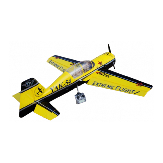
- Page 1 88 inch YAK-54 ARF Instruction Manual ©Copyright 2007 Extreme Flight RC, Ltd.
- Page 2 THIS IS NOT A TOY! Serious injury, destruction of property, or even death may result from the misuse of this product. Extreme Flight RC is providing you, the buyer with a very high quality model aircraft component kit, from which you, the buyer, will assemble a flying model.
- Page 3 Congratulations on your purchase of the Extreme Flight RC 88 inch YAK-54 ARF! This all new design is the result of applying what we have learned from 5 years of flying the Yak-54 design. Highly refined and thoroughly tested, this new Extreme Flight Yak-54 is being brought...
- Page 4 A few tips to ensure success and airframe longevity 1. We are very pleased with the level of craftsmanship displayed by the builders in our factory. Through many grueling test flights containing maneuvers that no aircraft should be subjected to, our Yak prototypes have remained rigid and completely airworthy.
- Page 5 Hardware Your new Extreme Flight 88 inch Yak includes all necessary hardware with the exception of main wheels, axles and collars. These items were omitted as I have been unable to source satisfactory versions of these items in China. I recommend Dubro 3/16”...
- Page 7 Let’s Begin! Elevator Assembly 1. Locate the horizontal stabilizer/elevator assemblies as well as the composite control horns and base pieces from the elevator hardware package. 2. Use a sharp #11 blade to open the 2 slots near the bottom leading edge of the elevator.
- Page 8 3. Insert the 2 control horns into the base plate as shown in the following picture. Carefully insert the control horns into the slots and push down until the base plate is flush with the control surface. Use a fine tipped felt marker to trace the outline of the base plate onto the covering.
- Page 9 4. Use some denatured alcohol to remove any residue or oils from the composite control horns and base plate. If you wish to paint the control horns for a more finished appearance now is the time to do so. Use some fine sandpaper to prepare the control horns for paint.
- Page 10 6. Remove the covering from the holes for the hinges. We use an old soldering iron for this and it works well. Locate 4 hinges per elevator half. You will need to cut 2 hinges just beyond the second knuckle to clear the fiberglass tube socket in the stabilizer.
- Page 11 hole until the joint is about a ¼” from its final position and use a paper towel to remove the excess epoxy that has been forced from the hole. Push the hinge the rest of the way in and make sure the hinge pin is centered in the hinge line.
- Page 12 11. Before installing the elevator servos, I highly recommend that you temporarily install the servo arms and electronically center the servos. It will be much easier to match up the servos at this point than when they are installed. I also recommend that you thin a small amount of epoxy with a few drops of alcohol and apply a light coat to the inside of the stab and to the servo mounting rib as well as to the root rib and mounting tabs.
- Page 13 13. Thread 2 of the heavy duty ball links onto one of the 2 longer of the titanium pushrods. Remember that the ends of the pushrods are reverse threaded so that they can be adjusted like a turnbuckle without removing the linkage. Insert a 3mm socket head cap screw into the ball link and into the servo arm.
- Page 14 15. As mentioned previously, you may need to adjust the size of the servo arm exit slot to achieve maximum travel. A ¼” Drum sander in a moto-tool makes quick work of this. Repeat these steps for the other stab/elevator half. Before you set aside the stabs take a moment with your covering iron and go over all of the seams with a medium heat setting, paying special attention to the ends of thin trim stripes.
-
Page 15: Wing Assembly
Wing Assembly 16. The assembly process for the wing is almost identical to that of the stab/elevator. For this reason we will not go into quite as much detail as in the previous procedure. Remove the aileron from the wing panel. - Page 17 17. Locate the aileron servo mount and remove the covering from this area. Use a sealing iron to seal the edges of the covering to the sides of the servo opening. Take a few minutes to apply some CA to the joints of the servo rails and the ribs.
- Page 18 18. Attach a 12” servo extension to your servo and secure with thread or heat shrink tubing. Use the manufacturer supplied mounting hardware and install the servo with the output shaft toward the leading edge of the wing. 19. Electronically center your servo. We will fabricate the linkage much in the same way as the elevator linkage.
- Page 19 20. Before beginning the next assembly process, take a few minutes with your sealing iron on a medium heat setting and go over all seams, paying special attention to thin trim stripes and the seam at the leading edge of the wing. If there are wrinkles in the covering on the leading edge sheeting use a heat gun with a 100% cotton t-shirt to remove them and prevent digging into the wood with an iron.
-
Page 20: Rudder Assembly
Rudder Assembly 21. Locate the rudder, the rudder control horns and the 2 slotted base plates. Use a sharp #11 blade to remove the covering from the 2 pre- cut slots in the rudder. 22. Trial fit the 2 servo horns through the base plate and into their proper position flush against the rudder surface. - Page 21 23. Mix up some 30 minute epoxy and milled fiberglass and use a small blade to fill the 2 slots with epoxy. Use plenty of epoxy and be sure to completely fill the two slots. Use an epoxy brush to completely cover the areas on the rudder horns and base plate that will glue into the rudder.
- Page 22 25. Using the same procedure as before, attach the rudder to the rear of the fuselage with the four hinge points. 26. Use a sharp hobby knife to open the 2 holes in the bottom rear of the fuselage to expose the 2 pre-installed 3mm blind nuts. Slide the tiller arm of the tailwheel into the hole in the ball link and attach the tailwheel assembly to the bottom of the fuselage with the 2 medium length 3mm bolts and washers.
-
Page 23: Fuselage Assembly
Fuselage Assembly 27. We’ll begin by installing the landing gear. Locate the aluminum main landing gear. The gear may appear a bit flexible at first glance. This is by design. The long moment arm of the landing gear puts a lot of stress on the gear mounts. - Page 24 28. Place a washer on one of the 4mm mounting bolts and insert them through the holes you just drilled from inside the fuselage.
- Page 25 29. Secure the landing gear with 4 washers and nylon insert lock nuts. 30. Attach the landing gear fairings with silicon glue. 31. Locate the 2 wheel spats and 2 plywood mounting plates. Use sandpaper to scuff the inside of the spat for better glue adhesion. Drill a hole as shown in each ply plate about ¼”...
- Page 26 32. Glue the ply mounting plate to the spats as shown with 30 minute epoxy. Once dry drill through the fiberglass spat at the location of the hole in the plywood plate. 33. Install your choice of axles and slide the spat over the axle and into position against the landing gear leg.
- Page 27 40 bolt. Use blue Loctite on ALL bolts. Slide a wheel collar onto the axles followed by the wheel and finally another collar to retain the wheel. You may need to trim the spat to clear the wheel.
- Page 28 34. Next let’s install the engine. We have made this process very easy. The center and offset marks have been scribed into the front of the firewall with a laser. Your firewall may also have holes scribed as well… DO NOT USE THESE HOLE LOCATIONS 35.
- Page 29 36. Use the recommended mounting bolts to mount the engine to the firewall. You will need to use standoffs to get the motor to 6.7 inches from the firewall to the engine thrust washer.
- Page 30 Remove the engine and brush a coat of alcohol thinned epoxy onto the exterior and interior of the motor box. When dry permanently mount the motor. Be sure to use some large washers behind the firewall to better distribute the load. Again, use blue Loctite on all bolts. 37.
- Page 31 38. Assemble the included Dubro 20 oz tank. Make sure to use the gas conversion stopper and Tygon tubing for all plumbing. Use nylon cable ties to secure the tank to the tank tray. The tank should butt up against the partial former in front of the wing tube.
- Page 32 39. Here is where we installed our fuel dot. 40. Once all plumbing is completed and throttle servo and linkage is installed glue the top of the motor box in place with 30 minute epoxy. This piece is NOT optional as it adds an enormous amount of strength and rigidity to the motor box.
- Page 33 41. If you are planning to use a tuned pipe or canister now is the time to install it.. You will need to remove the covering, center stringer and parts of 2 formers to open the pipe tunnel. Seal the edges of the covering to the edges of the pipe tunnel and paint a thin coat of alcohol thinned epoxy to seal the wood in the tunnel.
- Page 34 mount with a nylon cable tie. Pictures are much better for this!
- Page 37 43. Locate the rudder servo tray in the hardware package. Trial fit the tray to the mounting rails and mark the center on the rails and tray for easy alignment once glue is applied. Apply 30 minute epoxy to the tray and clamp this assembly to the servo rails and allow to dry.
- Page 38 44. Once this assembly has dried install your rudder servo using the supplied hardware with the output shaft toward the front of the plane. We recommend the use of one of the new “mega-torque” standard size servos such as the Hitec HS-5955 or the JR 8611A or 8711 for this position.
- Page 39 45. Next let’s install the pull-pull rudder cables. First remove the covering from the exit slots at the rear of the fuselage as shown. 46. Assemble one end of the linkage by inserting the pull-pull cable into a crimp, through the hole in the brass pull-pull fitting and back through the crimp.
- Page 40 47. Insert the bare end of the cable into the slot in the rear of the fuselage and feed it forward through the hole in the former that is positioned just in from of the slot. Pull the cable forward into the canopy area and make up the same type of linkage as you did previously.
- Page 41 48. Here is where we installed our switches on each side of the fuselage. After opening the hole with a new hobby blade we soaked the surrounding wood with thin CA before installing the switch.
- Page 42 49. If you plan to use the supplied louver plate in the front of the cowl now is the time to install it. Remove the lip from the circumference of the louver plate with a pair of scissors. You will also want to open the louvers in front of the engine cylinder for adequate cooling.
- Page 43 50. Slide the cowl into position. You should allow at least 1 inch clearance between the cowl and spinner backplate for maximum prop efficiency. This means the rear of the cowl will extend beyond the F1 former by about ¾”. I like to place a strip of Blenderm tape across the top front of the hatch that will fit under the cowl to keep the paint from getting scuffed.
- Page 45 52. Now let’s install the stab/elevators. You will need to attach 36 inch servo extensions to the elevator servos. If you plan to remove the stabs for transport you will need longer extensions. Open the holes in the rear side of the fuselage to expose the pre-mounted 3mm blind nuts.
- Page 46 53. Slide the stab halves onto the carbon fiber stab tube and secure with a 3mm bolt and washer inserted through the mounting tabs and into the pre-mounted blind nuts. Make sure to use a drop of blue Loctite on these bolts.
- Page 47 54. The canopy is retained by the 2 4mm bolts and bonded sealing washers. Before flying the Yak run a bead of RC-56 canopy glue all along the intersection of the canopy and its wood frame, front and back and both sides. This glue dries clear, is water soluble and is easy to clean up.
-
Page 48: Control Surface Throws
Set-up and trimming Besides basic assembly, this is the most important part of preparing your airplane for flight. It can also be the most time consuming, but once your plane is properly dialed in you will agree it was time well spent. A common phone call I get goes like this: “I can’t get my plane to fly right. - Page 49 The Yak exhibits very little coupling in knife edge flight. There is virtually no coupling when using the small amount of rudder needed for point rolls or slow rolls. When flying slow high alpha knife edge you may experience a small amount of coupling.
- Page 50 DA50-R Mounting Template WHEN PRINTING THIS TEMPLATE... make sure under PAGE HANDLING that PAGE SCALING is set to NONE...
Need help?
Do you have a question about the YAK-54 ARF and is the answer not in the manual?
Questions and answers