Advertisement
Quick Links
Advertisement

Subscribe to Our Youtube Channel
Related Manuals for Extreme Flight YAK-55SP-Electric


Summary of Contents for Extreme Flight YAK-55SP-Electric
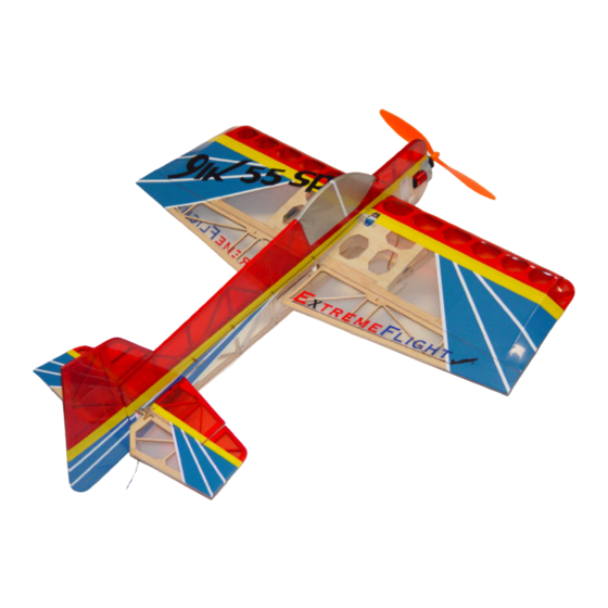
- Page 1 YAK-55SP-E lectric Instruction Manual ©Copyright 2004 Extreme Flight RC...
- Page 2 THIS IS NOT A TOY! Serious injury, destruction of property, or even death may result from the misuse of this product. Extreme Flight RC is providing you, the buyer with a very high quality model aircraft component kit, from which you, the buyer, will assemble a flying model.
-
Page 3: Wing Assembly
Additional Items needed to complete assembly 4 sub micro servos (we use and recommend the Hitec HS-55) 1 micro receiver (the Hitec Electron 6 is our choice) 3S1P Lithium Polymer battery pack (we use the Thunder Power 1320 mah pack) Connectors for attaching the battery to the ESC (we use the JST style connector) Wing assembly 1. - Page 4 3. Turn the wing over and remove the covering from the 2 rectangular holes in the aileron (one per aileron). Use some medium CA to glue the laser cut plywood control horns in place, mak- ing sure that they are perpendicular to the aileron. Put the wing aside for now. 4.
- Page 5 5. Locate the rudder and the remaining laser cut plywood control horn. Remove the covering from the rectangular hole in the LEFT side of the rudder. Using medium CA, glue the conrol horn into the slot on the LEFT side. 6.
- Page 6 7. Using a sharp #11 hobby knife, remove the covering from the wing and stabilizer slots. Use a sealing iron to secure any loose edges. 8. Trial fit the wing and stab into the fuselage. Once you slide the stab into the fuselage slot, slide it to the rear of the slot, leaving just enough room for the elevator to clear the rear post, allowing uninhibited movement of the elevator.
- Page 7 11. Using the lines you have drawn as a reference, use your hobby knife or a fine tipped solder- ing iron to open 4 small holes in the covering on each side of the fuselage at the vertical cross member. Use medium CA to glue the pushrod guides to the vertical cross member. Use the picture below for reference.
- Page 8 14. Attach the wing using 4 of the wood screws that are provided in the hardware package. The screw should be inserted through the wing mounting tab, through the fuselage and secure itself in the plastic wing screw retainers that you just glued in place in the previous step. 15.
- Page 9 17. Locate the small 1/16th balsa rectangle in the hardware package. 18. Use a sanding block to shape the piece of balsa into a wedge. 19. Use a single drop of medium CA to glue the wedge to the front of the fuselage.This will provide you with a small amount of right thrust to counteract the spiral slipstream effect.
- Page 10 20. Slide the motor/gearbox assembly onto the front of the fuselage, and press it flush against the balsa wedge. When viewed from the top the motor/gearbox should be angled to the right by about 2 degrees. Drill 2 1/16th“ holes through the gearbox and into the mounting beam. Insert the 2 woodscrews with the large heads into these holes and tighten until snug.
- Page 11 22. Insert the pre-formed wire landing gear into the slot and secure with one of the supplied nylon cable ties. 23. Slide the wheels onto the wire landing gear, and secure plastic wheel retainer with a drop of CA. A few words about the landing gear If you fly from a grass field we highly recommend that you leave the landing gear off of the Yak.
- Page 12 24. If you are using a motor and ESC from another manufacturer please follow their instruc- tions for attaching these units to each other and the plane. If using the Extreme Flight BL-20 brushless motor and speed controller, please refer to the instruction addendum at this time.
- Page 13 27. Glue a strip of Velcro to the back of your battery and mount as shown. 28. Drill a small hole in the rear bottom of the fusleage and install the pre-bent wire tail skid. Secure with a drop of CA.
- Page 14 29. Slide the 2 long wire pushrods through the pushrod guides from the front. You will attach the pre-bent “z-bend” at the servo arm and make a 90 degree bend on the other end at the con- trol horn on the control surface. Push the wire through the hole in the control horn and retain with one of the small laser cut plywood rings.
- Page 15 Set-up and Flight Trimming Please devote the first couple of flights to dialing in your Yak. The CG range for the Yak that we have found to be ideal starts at 3.25” from the leading edge of the wing and extends to 3.75” from the leading Edge of the wing..
Need help?
Do you have a question about the YAK-55SP-Electric and is the answer not in the manual?
Questions and answers