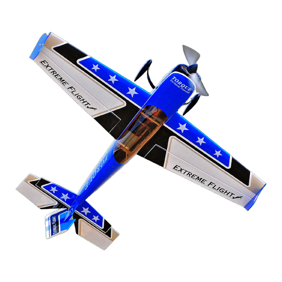
Extreme Flight 125" EXTRA 300 Assembly Manual
Arf airplane
Hide thumbs
Also See for 125" EXTRA 300:
- Instruction manual (28 pages) ,
- Instruction manual (12 pages)

Related Manuals for Extreme Flight 125" EXTRA 300


Summary of Contents for Extreme Flight 125" EXTRA 300
- Page 1 125" EXTRA 300 Assembly Manual...
- Page 2 Extra with minimal effort. The Extra 300 was designed to excel at IMAC and invitational sequence flying. It is also a very capable 3D aircraft in the hands of an experienced pilot.
- Page 3 Wing assembly (Please note that we highly recommend the use of 3 ultra torque servos for aileron actuation. We did extensive testing using both 2 and 3 servos and the gain in roll and snap performance using 3 servos is by far worth the investment in additional servos and the time required to properly set them up).
- Page 4 4. Use a sharp hobby blade to remove the covering over the slots at each of the 3 locations where the dual truss control horns will be installed. Place the horns into the base and insert into the slots in the aileron. Trace around the base with a fine tipped felt marker. 5.
- Page 5 6. Scuff the portion of the control horns that will be glued into the aileron with sandpaper to remove the glossy sheen and clean with denatured alcohol. Mix up some 30 minute epoxy (I prefer Mercury Adhesives 30 minute formula). Use a piece of pushrod or old hobby blade to fill the slots in the aileron with epoxy.
- Page 6 7. Use a sharp hobby blade to remove the covering at the location of each servo and seal the edges with a hot trim iron. Take a few minutes and saturate all joints of the servo mounting trays with CA. 8.
- Page 7 9. It is highly recommended that you use a servo programmer, Matchbox or power distribution unit to make sure all 3 servos work in unison. We use the Hitec 7955s and 7950s in our aircraft in conjunction with the Hitec programmer and have been able to get the servos matched perfectly with very little current draw.
- Page 8 Rudder preparation and installation 15. This step is also very important-please pay close attention. There are 2 sets of control horns provided for the rudder. The larger horn set is to be used if you intend to use a pull- pull set-up with the rudder servos mounted inside the fuselage under the canopy.
- Page 9 16. Using the same methods as used previously with the ailerons and elevator, install the fiberglass rudder horns on each side of the rudder. The rudder is hinged using the same method as with the ailerons and elevators. Place a few drops of blue Loctite on the threaded portion of the rudder hinge pin and insert into rudder.
- Page 10 17. There are 2 additional plywood trays included to accommodate various pull-pull set- ups. One tray allows the use of up to 3 standard size high torque servos ganged together. The additional hardware required for this set-up is not included in this kit. Also included is a tray to allow the use of a single Seiko industrial grade servo.
- Page 11 Fuselage assembly 18. Let's start by getting the landing gear mounted. Use the supplied 8mm bolts, nylon insert lock nuts and washers to mount the carbon fiber landing gear to the bottom of the fuselage. The straight portion of the gear leg should be oriented toward the front of the aircraft.
- Page 12 19. The landing gear fairings add a nice scale touch to the aircraft but are not necessary. If you wish to use them, slit the supplied black neoprene tubing length wise with a sharp hobby knife. Push the tubing onto the rim of the fairing and secure with CA. Attach the fairing to the gear with "Goop"...
- Page 13 21. Mounting the engine is quite easy. There are laser inscribed reference marks on the front of the engine mounting plate. When looking at the front of the mounting plate the vertical line to the right of the center line should be used to allow for right thrust offset to counter spiral slipstream effect.
- Page 14 22. There are plywood tabs supplied for mounting your fuel tank. These are pushed up from inside the pipe tunnel and should be secured with epoxy. Due to the wide range of engines that will be used a gas tank is not provided. We have started making our own tanks from 64 ounce juice bottles using brass fittings available from B&B Specialties.
- Page 15 24. Cowl mounting is very easy! The cowl is secured with 3 4mm screws. It is best to insert the longest of the 3 screws into the bottom of the cowl and secure first, then the top 2 screws as shown. Be sure to use a washer and a generous amount of blue Loctite to prevent the screws from backing out.
- Page 16 25. There are 2 blind nuts pre-installed in the rear bottom of the fuselage for mounting the carbon fiber tail wheel assembly. Before installing this assembly, file flat spots on the tail wheel wire so that all set screws from the various collars seat properly. Use a drop of blue Loctite on each setscrew.
- Page 17 Periodically inspect the carbon fiber landing gear and carbon wing and stab tubes for signs of distress and replace if necessary. Thanks again for your purchase of the Extreme Flight RC 40% Extra 300 ARF. We hope it brings you as much excitement and joy as we have experienced flying ours.
Need help?
Do you have a question about the 125" EXTRA 300 and is the answer not in the manual?
Questions and answers