
Subscribe to Our Youtube Channel
Related Manuals for Extreme Flight 2 Meter Vanquish F3A


Summary of Contents for Extreme Flight 2 Meter Vanquish F3A
- Page 1 2 Meter Vanquish Assembly Manual ...
- Page 2 If you are not willing to accept ALL liability for the use of this product, please return it to the place of purchase immediately. Extreme Flight RC, Ltd. guarantees this kit to be free of defects in materials and workmanship for a period of 30 DAYS from the date of purchase. All warranty claims must be accompanied by the original dated receipt.
- Page 3 A few tips to ensure success 1. We are very pleased with the level of craftsmanship displayed by the builders in our factory. Through hundreds of grueling test flights containing maneuvers that no aircraft should be subjected to, our prototypes have remained rigid and completely airworthy. However, it is impossible for us to inspect every glue joint in the aircraft.
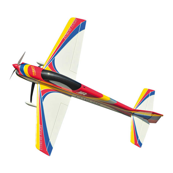
- Page 4 Congratulations on your purchase of the Extreme Flight RC 2 meter Vanquish! The Extreme Flight 2 meter Vanquish is our attempt to provide the pattern community with a very competitive, low cost alternative to the multi-thousand dollar composite airframes currently dominating the competition circuit.
-
Page 5: Stab And Elevator Assembly
Let's begin! Stab and Elevator Assembly Parts and tools needed for this 1. Locate the horizontal stabilizer/elevator assemblies as well as the composite control horns and base plates from the elevator hardware package. Use a sharp #11 blade to make a cut in the covering over the 2 slots for the elevator control horns on the bottom of the elevator surface. - Page 6 2. Insert the 2 control horns into the base plate and trial fit the horns into the slot and make sure they seat properly against the base and elevator surface. Score covering around the base plate with X-acto knife and lift the covering away from the elevator to expose the balsa underneath.
- Page 7 3. Scuff the portion of the G10 control horns that will be inserted into the elevator with sandpaper and insert them into the base plate. 4. Apply 30 minute epoxy to the slots and thoroughly coat the horns and base plate bottom. Reinsert the assembly into the elevator and wipe away any excess epoxy with a paper towel and denatured alcohol.
- Page 8 5. Place a 3mm bolt through the horns to help insure proper alignment and set aside to dry. Repeat for the other elevator half.
- Page 9 6. Place the elevator back on the stab, making sure the hinges are centered between the elevator and stab. Deflect the control surface to full deflection. Use a fresh bottle of thin CA and a fine tube applicator to apply a couple drops to each hinge.
- Page 10 7. Cut away the covering around the servo horn opening on the bottom of the stab with a sharp #11 blade.
- Page 11 8. Locate and remove the covering for the Stab adjuster threads on top and bottom of the stab halves.
- Page 12 9. Locate the 2 set screws and install into holes about 5 or 6 threads...
- Page 13 10. Now is a good time to electronically center the 2 Elevator servos, This will aid aligning the elevator horns when assembling the servos in the stab. We used the JR 3421 for the elevators with great results.
- Page 14 Install the servo into the servo bay using the manufacturers supplied hardware. Install servo with output shaft to rear of assembly. We highly recommend the Dubro Super Strength servo arms for all control surfaces. Although the long arm is pictured we recommend using the outside hole on the shortest supplied arm.
- Page 15 Seal the bottom of the hinge gap with a strip of Ultracote or Blenderm tape. Be sure to fully deflect the control surface when applying the tape or Ultracote to allow full deflection once the gap is sealed. Repeat this process for the other stab/elevator assembly.
-
Page 16: Wing Assembly
Wing Assembly 14. Parts and tools needed to assemble wing panels. The wing panel assembly is very similar to the techniques used to assemble the horizontal stabs. Locate the 2 horn slots, trim back the covering under the horn plates and glue into place the composite horns just as you did on the stab. - Page 19 15. Install aileron hinges as previously done on the elevators. Deflect aileron back to full deflection and glue both sides of hinge using fresh thin CA glue. Once dry work back and forth to remove stiffness.
- Page 20 16. Locate the Aileron servo bay and remove covering to expose servo rails. 17. The Aileron servo will need a 6 inch extension added to the length of the servo. I recommend joining the two leads with wax coated dental floss.
- Page 21 18. Use a length of thin wire to pull servo lead thru the wing panel.
- Page 22 19. Install aileron servo using the manufacturers hardware. We used the JR 9411with great results. Electronically center servo and attach Du-bro servo horn. 20. Assemble ball links and pushrod as done previously.
- Page 23 21. Using the Du-bro horn, install the linkage using the hole ¾ inch from center of servo output shaft. 22. Repeat this procedure on the other wing. Seal hinges with tape or covering, clean and set aside.
-
Page 24: Rudder Preparation
Rudder Preparation 23. Locate the rudder, the rudder control horns and the 2 slotted base plates. Use a sharp #11 blade to remove the covering from the 2 pre-cut slots in the rudder. Trial fit the 2 servo horns through the slots in the rudder and into their proper position. -
Page 28: Fuselage Assembly
Fuselage Assembly 24. Prep the fuselage assembly by removing the covering over areas such as wing tubes, wing adjusters, servo wire exits, wing retainer screw holes, landing gear slots, stab tube socket and adjusters, fuselage air exits located on the bottom of fuselage and rudder cable exits with a new #11 blade. - Page 30 25. Trial fit rudder assembly onto fuse. Once satisfied with fit glue hinges with thin CA glue.
- Page 31 26. Locate tail wheel assembly and mount to fuselage as shown.
- Page 32 27. Locate the carbon stab tube & aluminum stab adjuster rod. Slide them into the stab socket and center them in the fuselage. Feed the elevator servo extensions thru the fuse & then slide stab assemblies onto the tubes. We will cover the stab incidence adjustment a little later.
- Page 34 28. Install rudder servo on the servo rail under the canopy. The output shaft should be oriented toward the rear of fuse. We used the JR 8411 for the rudder with great results. 29. Locate the exit hole for the pull-pull cables in the lower rear portion of the fuselage.
- Page 35 30. Locate the carbon fiber landing gear legs. Slide gear legs into slot with the sweep of the gear leg to the rear of the plane. The screws go in from the inside of the fuselage as shown. Once legs are secured to the fuselage assemble the wheel axles as shown &...
- Page 38 31. Mount your ESC as shown on the bottom of motor box with small wood screws or Velcro. It will be easier to do your soldering before installing it into airframe.
- Page 39 32. Mount your motor with the 4 supplied screws & washers. We have provided enough space to mount most makes of outrunner motors currently used in pattern/F3A flying. If using the recommended Torque motor we have supplied plywood spacers to provide the proper distance between the face of the motor box and the spinner back plate.
- Page 40 33. Secure the cowl chin by inserting the provided screw and washer into the pre-installed blind nut.
- Page 41 34. Locate the wing adjuster plates & 4 screws. Install onto adjuster base located on inside of fuse as shown. Do not tighten screws completely until later.
- Page 42 Wing and stab incidence adjustment 35. Items needed are a level & Incidence meter. Install wings onto fuselage with the carbon fiber tube. Do not use the wing hold down screws for this adjustment. Place level on the flat area of the canopy fuse base. Level your plane so that bubble is centered as shown.
- Page 45 38. Once final adjustments are made secure stab halves to fuselage with a 3mm bolt as shown. 39. Wings are secured with nylon thumbscrews inserted from inside fuselage and threaded into pre-installed blind nuts in wing root. 40. Secure batteries with Velcro on the battery and battery tray as well as with a Velcro strap.
- Page 47 41. Secure canopy with spring loaded hatch latch. Be sure hatch pin is fully engaged into canopy! Since this mechanism is manipulated each flight I had my local graphics shop cut a patch from carbon fiber vinyl to prevent the covering around the hatch pin from becoming frayed.
- Page 48 Elevator: 8-10 degrees 20 degrees Rudder: 10-12 degrees 20-25 degrees Once again, thank you for your purchase of the Extreme Flight RC 2 meter Vanquish. I hope it brings you much joy! See ya at the flying field! Chris Hinson...
Need help?
Do you have a question about the 2 Meter Vanquish F3A and is the answer not in the manual?
Questions and answers