Advertisement
Quick Links
Advertisement

Related Manuals for Extreme Flight 50cc Edge 540T ARF


Summary of Contents for Extreme Flight 50cc Edge 540T ARF
-
Page 1: Instruction Manual
50cc Edge 540T ARF Instruction Manual Copyright 2009 Extreme Flight RC 1 ... - Page 2 THIS IS NOT A TOY! Serious injury, destruction of property, or even death may result from the misuse of this product. Extreme Flight RC is providing you, the consumer with a very high quality model aircraft component kit, from which you, the consumer, will assemble a flying model.
- Page 3 A few tips to ensure success 1. We are very pleased with the level of craftsmanship displayed by the builders in our factory. Through hundreds of grueling test flights containing maneuvers that no aircraft should be subjected to, our prototypes have remained rigid and completely airworthy. However, it is impossible for us to inspect every glue joint in the aircraft.
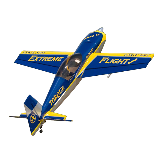
- Page 4 The performance ability of the Extreme Flight RC Edge 540T is incredible! If aggressive 3D flying is your passion, then the new Extreme Flight RC 50cc Edge 540T is the airframe you've been waiting for. Long heralded as the ultimate 3D platform, the Edge series of aircraft are known for their unmatched stability in high alpha flight and their aggressive gyroscopic tumbling maneuvers.
- Page 5 Elevator 1. Locate the horizontal stabilizer/elevator assemblies as well as the composite control horns and base plates from the elevator hardware package. Use a sharp #11 blade to make a cut in the covering over the 2 slots for the elevator control horns on the bottom of the elevator surface.
- Page 6 3. Remove the horn assembly and use your #11 blade to remove the covering from inside the ink line you traced around the control horn base. Wipe away the ink line with a paper towel soaked in denatured alcohol. Scuff the portion of the horns that will be inserted into the elevator with sandpaper.
- Page 7 7 ...
- Page 8 8 ...
- Page 9 4. In this step I will outline the procedure we use to install the hinges. There are several ways to do this and several adhesives you can use. We will describe the way we do it, as this method has proven itself over many years of model building. If you are new to this type of hinging process then I recommend that you install a single hinge first just to acquaint yourself with this method.
- Page 10 10 ...
- Page 11 5. After the hinges have dried thoroughly, pull on them to make sure they are properly installed. The hinges will probably feel a little stiff as it is almost impossible to get all of the glue out of the knuckle joint. Use a fine tipped hypodermic needle and place one (only one!) drop of acetone on each side of the hinge pin.
- Page 12 7. Install the elevator servo using the manufacturer supplied mounting hardware with the output shaft toward the front of the stab. It will be easier to electronically center the servo and install the servo arm before screwing the servo into position. We recommend the SWB 1.5 inch servo arm.
- Page 13 8. Locate 2 ball links and a titanium turnbuckle pushrod. Thread the ball links onto the pushrod and install using the supplied 3mm bolts, nuts and washers as shown in the picture. You may find it necessary to enlarge the slot in the bottom of the stab to allow for maximum travel.
-
Page 14: Wing Assembly
Wing Assembly 10. The assembly process for the wing is almost identical to that of the stab/elevator. For this reason we will not go into quite as much detail as in the previous procedure. Remove the aileron from the wing panel. Locate the 2 slots for the control horns and remove the covering from the slots with a sharp #11 blade. - Page 15 11. Locate the aileron servo mount and remove the covering from this area. Use a sealing iron to seal the edges of the covering to the sides of the servo opening. Take a few minutes to apply some CA to the joints of the servo rails and the ribs. 12.
- Page 16 13. Before beginning the next assembly process, take a few minutes with your sealing iron on a medium heat setting and go over all seams, paying special attention to thin trim stripes and the seam at the leading edge of the wing. If there are wrinkles in the covering on the leading edge sheeting use a heat gun with a 100% cotton t-shirt to remove them and prevent digging into the wood with an iron.
- Page 17 17 ...
- Page 18 18 ...
-
Page 19: Fuselage Assembly
Fuselage Assembly 15. We’ll begin by installing the landing gear. Locate the aluminum main landing gear, 4 4mm bolts, lock nuts and washers. Insert the gear into the slot on the bottom of the fuselage and center it in the slot. Secure the landing gear with 4 4mm bolts, washers and nylon insert lock nuts by inserting the bolts and washers into the pre-drilled holes in the aluminum gear mounts inside the fuselage with a long T-handle wrench. - Page 20 17. When satisfied with the position of the wheel pants, drill a hole though the plywood plate that is glued inside the pant at the location of the hole in the landing gear. Secure the pant in position with the provided 3mm bolt and blind nut. Repeat this process for the remaining wheel pant.
- Page 21 19. Assemble the tailwheel assembly as shown. For best results file a flat spot at the location that each set screw will seat and use a drop of blue Loctite on each set screw. 20. Place the tailwheel assembly on the rear bottom of the fuselage and secure with a piece of tape.
- Page 22 21. Mount the tiller arm as shown and insert the ends of the springs into the holes in the ends of the arms and bend to secure. 22. Next let’s install the motor/engine. We have made this process very easy. The center and offset marks have been scribed into the front of the firewall with a laser.
- Page 23 Distance from the front face of the motor box to the motor drive washer is 6.32"(This is the length of the DA-50 with 2.5 inch standoffs). Drill holes at the marked locations and install the engine using the recommended mounting bolts. 23 ...
- Page 24 23. Install your rudder servo using the supplied hardware with the output shaft toward the front of the plane. We used the Hitec 5955 and Hitec 7955 in our prototypes with great results. I highly recommend a servo with 280+ ounce inches of torque for best results. We are using the SWB 4”...
- Page 25 25. Assemble one end of the linkage by inserting the pull-pull cable into one of the aluminum tubes, through the hole in the brass pull-pull fitting and back through the aluminum crimp tube. Loop the cable back through the crimp tube a second time and crimp with side cutters.
- Page 26 28. Install your choice of throttle servo in the location in the bottom of the motor box. If using a tuned pipe or canister you will need to install a couple of 3/8" hardwood rails to elevate the servo and prevent it from being too close to the header. If using a standard muffler simply bolt the servo into the pre-cut hole.
- Page 27 30. Install your ignition unit on the side of the engine box using nylon cable ties. Make sure to put a piece of foam behind the unit to prevent damage from vibration. 31. Once you are satisfied with your throttle, tank and ignition installation glue the engine box top in place with epoxy.
- Page 28 Now let’s mount the cowl. 32. Before mounting the cowl place four strips of masking tape on the fuselage as shown and use a felt tipped marker to mark the location of the bolt holes in the cowl mounting tabs.
- Page 29 34. Secure the cowl using 4 3mm socket head bolts in conjunction with 4 bonded sealing washers as shown. 35. Install your switches, battery and receiver as well as prop and spinner to achieve proper center of gravity. Pipe or canister installation hints You may wish to install a tuned exhaust system in your aircraft.
- Page 30 The center of gravity range for the 50cc Edge 540T begins at 6.25 inches from the leading edge of the wing measured at the root and extends back to 7 inches. CG is determined with the EDGE in the upright position.
-
Page 31: Control Surface Throws
80-90% exponential. Again, this is just a starting point. Adjust to your liking. Thanks again for your purchase of the Extreme Flight RC 50cc Edge 540T ARF. I hope you enjoy assembling and flying yours as much as I have mine.
Need help?
Do you have a question about the 50cc Edge 540T ARF and is the answer not in the manual?
Questions and answers