Extreme Flight 78" EXTRA 300 ARF Instruction Manual
Radio control state-of-the-art r/c aerobatic aircraft and accessories
Hide thumbs
Also See for 78" EXTRA 300 ARF:
- Assembly manual (17 pages) ,
- Instruction manual (12 pages)
Table of Contents
Advertisement
Advertisement
Table of Contents

Related Manuals for Extreme Flight 78" EXTRA 300 ARF


Summary of Contents for Extreme Flight 78" EXTRA 300 ARF
-
Page 1: Instruction Manual
78" EXTRA 300 ARF Instruction Manual Copyright 2009 Extreme Flight RC... - Page 2 THIS IS NOT A TOY! Serious injury, destruction of property, or even death may result from the misuse of this product. Extreme Flight RC is providing you, the consumer with a very high quality model aircraft component kit, from which you, the consumer, will assemble a flying model.
- Page 3 A few tips to ensure success 1. We are very pleased with the level of craftsmanship displayed by the builders in our factory. Through hundreds of grueling test flights containing maneuvers that no aircraft should be subjected to, our prototypes have remained rigid and completely airworthy.
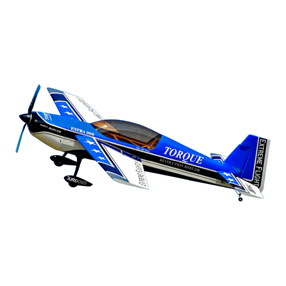
- Page 4 Congratulations on your purchase of the Extreme Flight RC 78 inch Extra 300 ARF! This aircraft is unique in that it is being offered in two versions: A gas/glow version and a dedicated electric version to satisfy the growing legions of electric power enthusiasts.
- Page 5 Your new Extreme Flight 50cc Extra 300 includes most necessary hardware with the exception of a spinner and electric motor mount. We highly recommend the use of the Extreme Flight 76mm Elite series electric spinner. You will find a complete pull-pull system, as well as high quality heavy duty ball links, titanium turnbuckle pushrods and composite control horns, and a carbon fiber tailwheel assembly.
- Page 6 Elevator 1. Locate the horizontal stabilizer/elevator assemblies as well as the composite control horns and base plates from the elevator hardware package. Use a sharp #11 blade to make a cut in the covering over the 2 slots for the elevator control horns on the bottom of the elevator surface.
- Page 7 3. Remove the horn assembly and use your #11 blade to remove the covering from inside the ink line you traced around the control horn base. Wipe away the ink line with a paper towel soaked in denatured alcohol. Scuff the portion of the horns that will be inserted into the elevator with sandpaper.
- Page 8 ...
- Page 9 ...
- Page 10 4. In this step I will outline the procedure we use to install the hinges. There are several ways to do this and several adhesives you can use. We will describe the way we do it, as this method has proven itself over many years of model building. If you are new to this type of hinging process then I recommend that you install a single hinge first just to acquaint yourself with this method.
-
Page 11: Wing Assembly
Wing Assembly 6. The assembly process for the wing is almost identical to that of the stab/elevator. For this reason we will not go into quite as much detail as in the previous procedure. Remove the aileron from the wing panel. Locate the 2 slots for the control horns and remove the covering from the slots with a sharp #11 blade. - Page 12 7. Locate the aileron servo mount and remove the covering from this area. Use a sealing iron to seal the edges of the covering to the sides of the servo opening. Take a few minutes to apply some CA to the joints of the servo rails and the ribs. 8.
- Page 13 9. Before beginning the next assembly process, take a few minutes with your sealing iron on a medium heat setting and go over all seams, paying special attention to thin trim stripes and the seam at the leading edge of the wing. If there are wrinkles in the covering on the leading edge sheeting use a heat gun with a 100% cotton t-shirt to remove them and prevent digging into the wood with an iron.
- Page 14 Rudder and tailwheel assembly and mounting 10. Locate the rudder, the rudder control horns and the 2 slotted base plates. Use a sharp #11 blade to remove the covering from the 2 pre-cut slots in the rudder. Trial fit the 2 servo horns through the slots in the rudder and into their proper position.
- Page 15 11. Locate a 2mm ball link from the hardware bag. Drill a hole 2 inches back from the leading edge of the rudder on the bottom of the rudder surface to accept the shank on the ball link. 12. Scuff the shaft of the ball link with coarse sandpaper. Mix up a small amount of 5 minute epoxy and apply it to the ball link and the hole in the bottom of the rudder.
-
Page 16: Fuselage Assembly
14. Use a rotary tool with a grinding bit or a small file to create a flat spot on the tailwheel wire for the set screws in the aluminum fittings to seat against. Reassemble the unit and apply Loctite to the threads on the setscrews and reinsert into the aluminum fittings and tighten snug. - Page 17 17. Locate the 2 fiberglass landing gear fairings and the black neoprene tubing. Use a sharp hobby blade and cut through one wall of the tubing horizontally along the length of the tubing. Press the tubing onto the edges of the fairing as shown and secure with thin CA.
- Page 18 18. Slide the fairings over the landing gear and against the sides of the fuselage. You may need to open the hole in the fairing slightly with a rotary tool bit for proper fit. Use a pencil to mark the location of the bottom of the fairing on the landing gear and then remove the fairing.
- Page 19 When satisfied with the position of the wheel pants, drill a 1/16" hole though the plywood plate that is glued inside the pant at the location of the hole in the landing gear. Secure the pant in position with a single wood screw. Repeat this process for the remaining wheel pant.
- Page 20 21. While the Extra is still upside down let’s install the rudder and finish up the tailwheel installation as well as opening the exit hole for the incoming air that cools the batteries. Apply 30 minute epoxy to the holes in the rudder post and to the rudder hinges. As you position the rudder onto the vertical fin, be sure the tailwheel tiller arm is inserted into the ball link.
- Page 21 22. Next let’s install the motor/engine. We have made this process very easy. The center and offset marks have been scribed into the front of the firewall with a laser. Holes have also been marked which correspond with the mounting holes for the cage mount used with our recommended Torque outrunner.
- Page 22 23. For mounting a gas engine, contact the engine manufacturer for a mounting template, print it and tape into position on the front of the firewall, being careful to align the vertical positioning mark with the laser scribed vertical line to the right of the center line and the horizontal positioning mark with the laser scribed horizontal line on the firewall.
- Page 23 26. Remove the covering over the holes in each side of the rear of the fuselage for the elevator servos. Attach a 36" extension to the servo lead and install the servos with the output shafts toward the rear of the fuselage using the manufacturer supplied mounting hardware.
- Page 24 Now let’s mount the cowl. 27. Before mounting the cowl place four strips of masking tape on the fuselage as shown and use a felt tipped marker to mark the location of the bolt holes in the cowl mounting tabs.
- Page 25 behind the F1 former and place the cowl into position, flush with the rear of the F1 former. Place your spinner (76mm) on the motor to help align with cowl. View the cowl from several angles to insure that it is positioned properly. When satisfied put the four tape strips back into position and drill a 1/8”...
- Page 26 This completes the assembly of the 78 inch Extra 300. As a final step clean the entire aircraft with glass cleaner, then apply a coat of spray-on wax and buff the finish to a high gloss. My favorite product for this is Eagle One Wet Wax AS-U-DRY, available in the automotive section of most Wal-Marts, K-marts, Sears, Targets, etc.
-
Page 27: Control Surface Throws
Again, this is just a starting point. Adjust to your liking. Thanks again for your purchase of the Extreme Flight RC 78 inch Extra 300 ARF. I hope you enjoy assembling and flying yours as much as I have mine.
Need help?
Do you have a question about the 78" EXTRA 300 ARF and is the answer not in the manual?
Questions and answers