Advertisement
Quick Links
Advertisement

Related Manuals for Extreme Flight F3A


Summary of Contents for Extreme Flight F3A
- Page 1 ANQUISH F3A ELECTRIC ARF Instruction Manual ©Copyright 2007 EXTREME FLIGHT RC, Ltd.
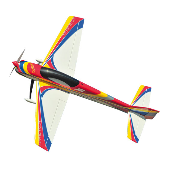
- Page 2 The Vanquish F3A can truly be assembled in an evening-buy it one day, fly it the next! As with all Extreme Flight RC airplanes, the proof is in the flying! The Vanquish flies precision aerobatics remarkably well and allows you to practice your AMA pattern or FAI F3A sequence almost anywhere.
- Page 3 Tips for Success-Please read before beginning assembly!!! 1. Read the instruction manual thoroughly before starting assembly. 2. We are very pleased with the level of craftsmanship exhibited by the workers in our factory. However, these are mass produced models. As with any ARF, take a few minutes to go over the model and add CA to high stress areas or any joints that appear to need more glue.
-
Page 4: Wing Assembly
Wing assembly 1. Locate a wing panel. Check to see that all hinges are centered between the wing and aileron. Hold the aileron fully deflected and apply a drop of thin CA to each hinge. Flip the wing over and repeat. 2. - Page 5 3. Locate the composite aileron control horn, aileron pushrod with z-bend and ez- connector. Remove the covering over the mounting hole for the control horn with your #11 blade. Scuff the part of the control horn that will glue into the aileron slot with fine sandpaper.
-
Page 6: Fuselage Assembly
Fuselage Assembly 5. Let’s mount the landing gear first. Locate the aluminum landing gear, (4) 3mm machine screws, (2) park flyer axles, (2) nylon insert lock nuts, (2) wheel collars, (2) wheel pants, (2) wheels and (2) plywood squares with slots from the hardware package. - Page 7 8. Open the gear slots in the side of the fuselage with a sharp hobby knife.
- Page 8 9. Insert the gear legs through the slots and retain with the (4) 3mm bolts and washers. Make sure to put a drop of blue Loctite on the bolt threads. The gear legs should sweep toward the rear of the plane. 10.
- Page 9 11. Add the 2 triangle support pieces to the motor box and secure with medium CA.
- Page 10 12. Open the horizontal stabilizer mounting slot in the rear of the fuselage with a sharp hobby knife. 13. Insert the elevator into the slot in the rear fuselage side. It must be inserted upside down with the counter balances facing the rear of the plane, then it can be rotated into the proper position.
- Page 11 16. Slide the elevator onto the hinges in the horizontal stab and glue in place with thin CA. Make sure the elevator is fully deflected when you apply the CA to insure maximum elevator travel is achievable. 17. Slide the vertical fin into its slot being careful to make sure the fin is properly aligned with the wing and stab and rear of fuselage.
- Page 12 19. Bend the wire with needle nose pliers as shown. 20. Drill a hole in the leading edge of the rudder to accept the wire and notch the leading edge of the rudder for the vertical portion of the wire. Mount the tailwheel bracket on the bottom of the fuselage as shown using 2 of the small wood screws.
- Page 13 21. Secure the rudder hinges with thin CA 22. Locate the elevator control horn. Use a sharp hobby knife to remove the covering from the elevator horn slot. 23. Glue the elevator horn in place with medium CA or epoxy. Make sure to scuff the surface of the control horn before gluing.
- Page 14 25. Place an ez-connector on the servo arm. Locate the elevator pushrod and insert the z-bend into the phenolic control horn and the other end into the ez connector. You may need to open the hole in the phenolic control horn slightly. Be careful not to over enlarge the hole.
- Page 15 26. Locate the (2) .060 carbon fiber reinforcement rods. Use a drill bit with a pen vise to open holes in the outer leading edge of the stab and in the solid wood part of the bottom rear of the fuselage as shown. 27.
- Page 16 28. Use a #11 blade to remove the covering from the slot near the bottom of the rudder. Locate the composite control horn for the rudder. Scuff the control horn to remove the glossy finish and glue into place in the slot in the rudder. Be sure to center the horn in the slot.
- Page 17 29. Mount the rudder servo as shown inside the fuselage. Use the supplied hardware to assemble the pull-pull cable system. There are 2 plastic guide tubes in the rear of the fuselage to accept the pull-pull cables. These tubes are located just below the elevator servo location.
- Page 19 Tighten until snug. 34. The battery should sit right in front of the receiver. Adjust the location of the battery to achieve proper CG. This concludes the assembly of the Vanquish F3A.
- Page 20 Radio Set-up and flight tips. CG range for the Vanquish is from 4.50”- 4.75” from the leading edge of the wing measured at the wing root. Correct CG should be easy to achieve by moving the battery along the length of the battery tray. Adjust to fit your flying style. Control surface recommendations are as follows: Elevator- 10 degrees low rates, 45+ degrees high rates.
Need help?
Do you have a question about the F3A and is the answer not in the manual?
Questions and answers