Advertisement
Quick Links
Advertisement

Related Manuals for Extreme Flight 60" laser ARF


Summary of Contents for Extreme Flight 60" laser ARF
-
Page 1: Instruction Manual
60" Laser ARF Instruction Manual Copyright 2013 Extreme Flight RC 1 ... - Page 2 THIS IS NOT A TOY! Serious injury, destruction of property, or even death may result from the misuse of this product. Extreme Flight RC is providing you, the consumer, with a very high quality model aircraft component kit, from which you, the consumer, will assemble a flying model.
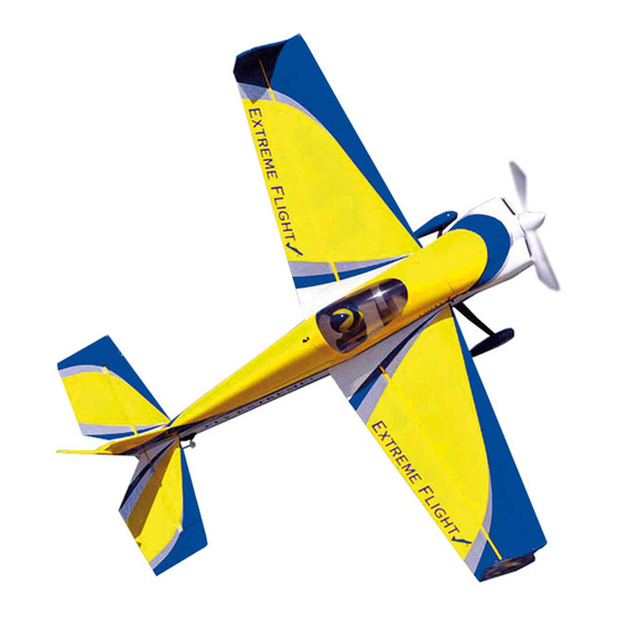
- Page 3 I am a huge fan of the Laser 200 and the late airshow legend Leo Loudenslager. I always knew that at some point Extreme Flight would have to produce a model of this iconic airframe. My goal was to honor the unique legacy of Leo and his Laser while bringing the model up to date to match the performance we have all come to expect from an Extreme Flight EXP series aircraft.
- Page 4 Items needed for completion: Masking tape. Hobby knife with #11 blades. Thin and medium CA. We highly recommend Mercury M5T thin and M100XF medium formulas as well as the Mercury glue tips. 30 minute epoxy. Mercury Adhesives Epoxies have worked very well for us. ...
- Page 5 Tips for Success: 1. Before starting assembly, take a few minutes to read the entire instruction manual to familiarize yourself with the assembly process. 2. Please take a few minutes and go over all the seams on the aircraft with a covering iron on a medium heat setting.
- Page 6 Let's begin! 1. Locate the 2 wing panels as well as the composite aileron control horns and base plates. Use a soldering iron or sharp hobby blade to remove the covering over the slot for the aileron horn. Make sure you are doing this on the bottom of the aileron! 2.
- Page 7 3. Remove the horn assembly and use a #11 blade to remove the covering from inside the ink line you traced around the control horn base. Wipe away the ink line with a cotton cloth or paper towel soaked in denatured alcohol. 4.
- Page 8 5. Insert the control horn into the base plate and apply 30 minute epoxy to the slot in the aileron and the scuffed potion of the control horn that will insert into the aileron. Use a zip tie to ensure the slot is completely filled with epoxy. 6.
- Page 9 7. Remove the aileron from the wing to ensure all hinges are centered between the wing and aileron. One way to ensure the hinges are centered is to fold them in half and re-install into the aileron using the crease as a reference point. 8.
- Page 10 9. Before installing the aileron servo, take a minute and apply some CA to the servo tray and the anti-rotation pins. 10. Before moving to the next step, it would be a good time to seal the hinge gap with a strip of Ultracote or Blenderm tape. Be sure to fully deflect the control surface when sealing the gap to allow for full deflection once the gap is sealed.
- Page 11 11. Attach a 6” servo extension to the servo and secure with thread or heat shrink tubing. Use the manufacturer supplied mounting hardware to install the servo with the output shaft toward the trailing edge of the wing. Electronically center the servo and install the second longest servo arm from the Dubro servo arm kit.
- Page 12 Fuselage Assembly 13. Locate the carbon fiber landing gear and secure the landing gear to the fuselage by inserting the 3mm bolt into a washer, through the carbon fiber gear and into the pre-installed blind nuts in the fuselage. Make sure to use a drop of blue Loctite on each bolt to prevent them from backing out.
- Page 13 15. Place the threaded portion of the axle through the hole in the landing gear and attach the lock nut and washer onto the axle. Slide the wheel pant into position over the axle and tighten the nut, making sure the wheel pant is positioned properly. 16.
- Page 14 17. Before installing the horizontal stab you will need to remove the piece of balsa at the rear of the stab slot. The factory leaves this piece intact so that the rear of the fuselage will remain true during the covering process and during transit. First place a couple strips of masking tape on the fuselage to give you a guide to cut by and to prevent the Ultracote covering from tearing.
- Page 15 19. Locate the horizontal stabilizer/elevator assembly. Turn it upside down on your building table and remove the covering over the right slot on the bottom of the elevator where the elevator control horn will be installed. Using the same process as with the ailerons, insert the horn into the base plate and into the slot.
- Page 16 21.Scuff the portion of the control horn that will insert into the elevator as well as the bottom of the base plate with sandpaper. Secure the control horn to the elevator with epoxy just as you did with the aileron horns. 22.
- Page 17 24. Insert the stabilizer into its slot and the carbon fiber wing tube into the fiberglass sleeve. Use a ruler to insure that the stabilizer is centered in its slot and compare the stabilizer to the wing tube to make sure it is properly aligned. Sand or shim the slot if necessary to ensure proper alignment.
- Page 18 26. Remove the covering over the slot on the right side of the rudder. Follow the same procedure as with the ailerons, Use a sharp hobby knife to remove the covering 1/16" inside the line you traced. Wipe away the ink line with a cotton cloth or paper towel soaked in denatured alcohol.
- Page 19 28. Slide the rudder onto the hinges in the vertical stab, making sure the hinges are centered between the rudder and stab. Also, make sure the rudder is flush with the top and bottom of the stab. Once satisfied, glue the hinges in place with thin CA making sure the rudder is fully deflected.
- Page 20 30. Attach a 24” servo extension to the elevator servo and secure with thread or heat shrink tubing. Use the hardware provided with the servos to install the elevator servo on the left side of the fuse with the output shaft toward the front of the aircraft. 31.
- Page 21 32.Using the same procedure as with the elevator, install the rudder servo on the right side of the fuse with the output shaft toward the front of the aircraft. Locate the long pushrod and 2 ball links and assemble the pushrod linkage as shown in the picture below.
- Page 22 34. Next, secure the radial mount to the motor using the provided short Phillip's head machine screws. Again be sure to use a drop of blue Loctite on each screw. 35. Secure the prop adapter using the 4 socket head cap bolts. Blue Loctite should be applied to each bolt.
- Page 23 36. Mount the Torque motor using the supplied 4mm black socket head cap bolts and washers. The bolts are to be inserted into the blind nuts which are pre-installed in the motor mount plate. Be sure to put a drop of blue Loctite onto each bolt to prevent them from backing out.
- Page 24 Mounting the Cowl 38. Tear 4 short pieces of blue painters tape from a roll. Place each piece of tape on the side of the fuselage so that each piece corresponds with one of the 4 cowl mounting tabs. Use a fine tipped marker to mark the location of the center of each mounting tab.
- Page 25 40. Remove the tape and secure the cowl with 4 of the included small wood screws that have the large heads. 41. Use a sharp hobby knife to remove the covering from the opening in the bottom of the fuselage under the canopy to allow cooling air to exit the fuselage. 25 ...
- Page 26 42. The wings are retained by inserting a 4MM bolt and washer through the tabs each wing at the side of the fuse just in front of the wing tube. Make sure the wings are pushed all the way in so the holes in the tab and fuse line up. Take care not to cross thread the bolts.
- Page 27 Set-up and Trimming The CG range for the Laser EXP starts at the front of the wing tube and extends to the rear of the wing tube. There is plenty of room on the battery tray to move your battery to achieve this CG location.
- Page 28 You may wish to apply all of your graphics before applying the coat of wax. Thanks again for your purchase of the Extreme Flight RC 60 inch Laser ARF. I hope you enjoy assembling and flying yours as much as I have mine.
Need help?
Do you have a question about the 60" laser ARF and is the answer not in the manual?
Questions and answers