Table of Contents
Advertisement
Installation & Operating Instructions
!
WARNING
!
WARNING
WARNING: If the information in these
instructions is not followed exactly, a fire
or explosion may result causing property
damage, personal injury or loss of life.
Do not store or use gasoline or other
flammable vapors and liquids in the vicinity
of this or any other appliance.
WHAT TO DO IF YOU SMELL GAS
• Do not try to light the appliance.
• Do not touch any electrical switch; do not
use any phone in your building.
• Immediately call your gas supplier from
a neighbor's phone. Follow the gas
supplier's instructions.
• If you cannot reach your gas supplier, call
the fire department.
Installation and service must be performed
by a qualified installer, service agency or the
gas supplier.
4002252-04
©2010, Miles Industries Ltd.
L
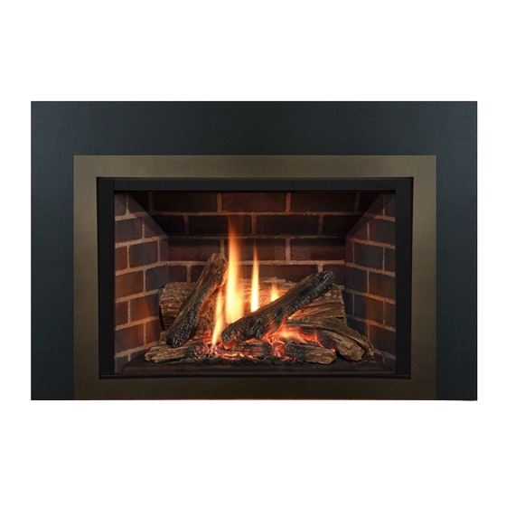
egend
Direct Vent Gas Insert
780IN (NG) & 780IP (LPG)
WARNING
HOT GLASS WILL
HOT GLASS WILL
HOT GLASS WILL
CAUSE BURNS.
CAUSE BURNS.
CAUSE BURNS.
DO NOT TOUCH GLASS
DO NOT TOUCH GLASS
DO NOT TOUCH GLASS
UNTIL COOLED.
UNTIL COOLED.
UNTIL COOLED.
NEVER ALLOW CHILDREN
NEVER ALLOW CHILDREN
NEVER ALLOW CHILDREN
TO TOUCH GLASS.
TO TOUCH GLASS.
TO TOUCH GLASS.
Manufactured by
MILES INDUSTRIES LTD., British Columbia, Canada
www.valorfireplaces.com
g4
INSTALLER: Leave this manual
with the appliance.
CONSUMER: Retain this manual
for future reference.
Please read this manual BEFORE installing
and operating this appliance.
This appliance may be installed in an
after-market permanently located,
manufactured (mobile) home where not
prohibited by local codes.
This appliance is only for use with the type
of gas indicated on the rating plate. This
appliance is not convertible for use with
other gases, unless a certified kit is used.
This appliance is a domestic room-heating
appliance. It must not be used for any other
purposes such as drying clothes, etc.
This appliance is suitable for installation in a
bedroom or bed sitting room.
Massachusetts: The piping and final
gas connection must be performed by a
licensed plumber or gas fitter in the State of
Massachusetts.
Ce guide est disponible en français sur demande.
Patent Pending
Advertisement
Table of Contents

Subscribe to Our Youtube Channel
Related Manuals for Valor Legend G4 780IN


Summary of Contents for Valor Legend G4 780IN
- Page 1 egend Patent Pending Direct Vent Gas Insert 780IN (NG) & 780IP (LPG) Installation & Operating Instructions WARNING WARNING WARNING HOT GLASS WILL HOT GLASS WILL HOT GLASS WILL CAUSE BURNS. CAUSE BURNS. CAUSE BURNS. DO NOT TOUCH GLASS DO NOT TOUCH GLASS DO NOT TOUCH GLASS UNTIL COOLED.
- Page 2 Thank You ... For purchasing a Valor by Miles Industries. Your new radiant gas heater is a technical appliance that must be installed by a qualified dealer. Each Valor fireplace is fully tested during the production process for your safety and comfort.
-
Page 3: Table Of Contents
Table of Content Safety and Warning Information..............4 ◊ Specifications ....................5 Overview ......................6 ◊ Dimensions ....................7 Cavity ......................7 ◊ Clearances ......................8 Venting ......................9 Installation Planning ..................10 Existing Fireplace Preparation ..............10 Appliance Preparation .................11 ◊ Supply Gas Installation ................14 Ceramic Panels Installation ................15 Ceramic Logs Installation ................16 Ceramic Rocks Installation .................19 Window Refitting ..................21... -
Page 4: Safety And Warning Information
Safety and Warning Information READ and UNDERSTAND all instructions carefully This unit MUST be used with a vent system as before starting the installation. FAILURE TO FOLLOW described in this installation manual. NO OTHER vent these installation instructions may result in possible fire system or components MAY BE USED. -
Page 5: Specifications
Safety and Warning Information Operating your fireplace for the first time. When It is also possible that these vapors could set off any operating your new fireplace for the first time, some smoke detection alarms in the immediate vicinity. vapors may be released due to the burning of curing These vapors are quite normal on new appliances. -
Page 6: Overview
Overview This appliance may ONLY be installed in an existing unaltered, functioning solid-fuel burning fireplace with a working flue and constructed of non-combustible material. DO NOT install into combustible construction. This appliance is NOT APPROVED for installation with a zero clearance kit. Chimney Terminal Cap Flashing 2 x 3”... -
Page 7: Dimensions
Dimensions 33” (838 mm) 24” (610 mm) 6’ (1.9 m) Fan power cord 3” (76 mm) Optional fan 3” 3” 15” (76 mm) (76 mm) (381 mm) 15” 4” Trim (381 mm) (102 mm) (sold separately) Gas line approx. 24“ (610 mm) 10”... -
Page 8: Clearances
Clearances WARNING Some materials or items, although safe, may discolor, warp, crack, peel, and so on because of the heat produced by the fireplace. Avoid placing candles, paintings, photos, and other items sensitive to heat around the fireplace. Combustible Mantel Clearances Mantel 1”... -
Page 9: Venting
Venting Typical Vent Installation See list of approved Venting Accessories on page 35 of this manual. NOTE: Flexible co-linear vent pipes may only be installed into existing non- combustible solid-fuel burning fireplaces and chimneys. Terminal Cap Vent Location The vent terminal must be located through the roof. -
Page 10: Installation Planning
Installation Planning Installer—READ THIS FIRST 14. Install ceramic panels and fuel bed. 15. Refit window. 1. YOU NEED TO KNOW FROM THE HOMEOWNER what accessories (surround, 16. Set-up remote control. screen, fan/blower, etc.) will be installed with 17. Verify operation and adjust aeration settings. this fireplace;... -
Page 11: Appliance Preparation
Existing Fireplace Preparation Gas Line Routing Combustible Mantels Plan the routing of the gas line before proceeding. Combustible mantel clearances must conform to those Utilize the existing hole for the gas line of the factory- required for the original solid-fuel fireplace into which built fireplace. -
Page 12: Window Removal
Appliance Preparation Window Removal The window is held in place by a spring-loaded lever on each side. 1. To remove the window, locate the levers on each side of the window towards the top. Using your finger, pull the lever towards you and unhook it from the window frame bracket. -
Page 13: Venting Installation
Appliance Preparation Venting Installation IMPORTANT: This appliance’s venting system is room sealed and therefore, does not require room air to be used in the combustion process. 1. Rough-in two 3” diameter vent liners into the existing chimney system from the roof. Be careful not to tear or damage the liners in the process. -
Page 14: Supply Gas Installation
Supply Gas Installation The gas supply inlet connection is a 1/2” NPT female. Pressure Test Points Gas shut-off valve supplied on the end of stainless The minimum supply pressure is given in the steel flexible connector. Flex connector is located on subsection Ratings of this manual—page 5. -
Page 15: Ceramic Panels Installation
Ceramic Panels Installation The following guidelines apply for all brick liners. 5. Rotate the anchor up and out of the way and slide the left hand side panel against the firebox side. 1. Remove the rear log support (3 screws). Rotate the anchor back down to hold the panel. -
Page 16: Ceramic Logs Installation
Ceramic Panels Installation 9. Reinstall the front brick support. 11. With logs only: Install the front bricks in front of the burner. 10. Reinstall the rear log support (3 screws). Its rear 12. With logs only: Slide the cast iron grate in the edge rests on the rear brick support ledge. - Page 17 Ceramic Logs Installation 2. Place the black glass piece on top of the burner and 4. Place the right front log with its left end flat on the move it forward to rest in the grooved recess of the glass. The notch in the log should place squarely on grate and center it.
- Page 18 Ceramic Logs Installation 6. Identify the top right log. It is the longest of the two 7. Place the top left log’s wider end on the peg of the remaining logs. Place its wider end on the front right front left log and rest its narrow end in the notch on log’s peg and rest its narrow end in the notch on the the rear log.
-
Page 19: Ceramic Rocks Installation
Ceramic Rocks Installation For ceramic logs, see previous section. Unpack the ceramic rocks very carefully to avoid damaging them. Install the rocks as shown. Please note that the position of some of the rocks identified in the following instructions is critical to ensure proper performance of the appliance. - Page 20 Ceramic Rocks Installation 4. Each rock is embossed 8. Identify the rocks 7, 9, 11 and 14. These rocks underneath with a number have one hole underneath and fit on the peg of and an arrow indicating the rocks 6, 8, 10 and 13 respectively. Install these its position.
-
Page 21: Window Refitting
Ceramic Rocks Installation 11. Optional: Lay the twigs on the rocks. They can be IMPORTANT: The rocks of the top row (14, 11, 9 placed as suggested below or elsewhere on the and 7) overhang slightly over the burner. rocks as long as they do not block the pilot flame or the burner flame. -
Page 22: Remote Control Initial Set-Up
Remote Control Initial Set-up The receiver and the handset of the remote control 5. With a sharp object, press and hold the receiver’s system must be initially synchronized before the first reset button until you hear one short and one long use. -
Page 23: Operation Check & Aeration Settings Adjustment
Operation Check & Aeration Settings Adjustment Operation Check In a few unusual installations, the flame picture may be improved by adjusting the aeration. The need for Turn the fireplace flame up and down using the adjustment should be determined only by operating the remote control to confirm that the full range of inputs appliance with the ceramic logs and window installed. -
Page 24: Remote Control Handset Wall Holder Installation
Remote Control Handset Wall Holder Installation The remote control kit for this fireplace comes complete with a wall-mounted holder. Packing Contents: Alternative 2 Alternative 3 This holder is not required in all installations 1 Wall Bracket A but is provided as an optional feature for 2 Screws B those customers who wish to mount the 1 Screw C... - Page 25 Owner’s Information Cleaning To remove the window for cleaning: WARNING 1. Find the levers on each side of the window towards DO NOT TOUCH THE GLASS WHILE IT IS HOT! the top. Using your finger, Let the fireplace cool first before cleaning it. pull the levers towards you Important - Glass cleaning - Mineral deposits and unhook them from the...
- Page 26 Owner’s Information Checks The appliance area must always be kept clear and free from combustible materials, gasoline and other A periodic check of the pilot and burner flames should flammable vapors and liquids. be made. Check after the fire has been on for at least 30 minutes.
- Page 27 Owner’s Information Servicing Automatic Turn Down/Shut-Off If any attention is required for your appliance, contact The remote control system is equipped with safety your supplier quoting the model number. It will be features which will turn down or shut off the appliance helpful if the appliance’s serial number can also be in certain circumstances.
-
Page 28: Remote Control Operation
Remote Control Operation NOTE: Before using the remote control system for the first time, the receiver and the handset must be synchronized. See the section Remote Control Initial Set-up on page 22 in this manual. Your fireplace remote control helps you get the comfort, convenience and aesthetics you want from your gas fireplace. The remote controls your fireplace in different ways. -
Page 29: Flame Height
Remote Control Operation Operation Modes STANDBY MODE—Ignited pilot only. MAN MODE —Manual Mode. You can use this mode to adjust the flame height up or down. ☼ TEMP MODE —Daytime Temperature Mode (appliance must be in Standby mode; pilot ignited): The room temp temperature is measured and compared to the set temperature. - Page 30 Remote Control Operation Time To set the time, follow the steps below. 1. The display indicates °C/24-hour or °F/12-hour clock. To change from one to the other, press and hold both the OFF and buttons until the display changes. 2. To set the time, hold down both the buttons until the display flashes.
- Page 31 Remote Control Operation Fan Setting (if equipped) The fan must be preset to function automatically when the fireplace is turned on. The fan is operated with the remote control system. It has 4 speed levels. On the remote control handset’s display, this icon ( ) represent the fan and this icon ( ) represents the speed.
-
Page 32: Options
786LSL—Ledgestone Liner Set 795CFK—Circulating Fan Kit 787EBL—Enamel Black Liner Set 796ALP—Adjustable Leveling Platform 788FBL—Fluted Black Liner Set 797FSB—Framed Safety Screen Black 789VRL—Valor Red Brick Liner Set 1265WSK—Wall Switch Kit Conversion Kit Fuel Bed (required) 780PGK—Conversion Kit to Propane Gas 781RSK—Rock Set 780NGK—Conversion Kit to Natural Gas... -
Page 33: Lighting Instructions
Lighting Instructions FOR YOUR SAFETY, READ BEFORE LIGHTING WARNING : If you do not follow these instructions exactly, a fire or explosion may result causing property damage, personal injury or loss of life. A. This appliance has a pilot which must be lighted by hand or by remote control. Follow these instructions exactly. To save gas, turn the pilot off when not using the appliance for a prolonged period of time. -
Page 34: Wiring Diagram
Wiring Diagram Optional Wall Switch Kit 1265WSK Connector Yellow Optional Fan Remote Control Battery Box Module 4 AA Batteries GV60 MAX Wiring Diagram... -
Page 35: Venting Accessories
Venting Accessories APPROVED DIRECT VENT SUPPLIERS FOR VALOR MODELS 739, 780, 785 & RF24DV Venting Parts Code / availability by Manufacturer Venting Parts Description Standard Co-axial 46DVA-VC 4DT-VC TM-4VT — HSDV4658-1313 — High Wind Co-axial 46DVA-VCH — — SV4CGV —... -
Page 36: Warranty
Warranty If you have a problem with this unit, please contact your dealer or supplier immediately. Under no circumstances should you attempt to service the unit in any way by yourself. The warranties in paragraphs 1 and 2 are provided only to the first purchaser/user of this unit, are not transferable and are subject to the conditions and limitations in paragraphs 3, 4 and 5. -
Page 37: Spare Parts
Spare Parts Part Part Code Description Code Description Number Number Exhaust slide assembly 4002287 Valve 4000873X Exhaust slide gasket 4000176 34” flex pipe with shut-off valve 4002475 Restrictor enclosure 4002330 Air shutter slider NG 4002345 Metal strip 4002329 Air shutter cover NG 4002346 Restrictor assembly 4002333... - Page 38 Ceramic platform—sand 4002439 Platform support assembly 4002663 Liner panels—complete set Ledgestone 786LSL Enamel black 787EBL Ceramic fluted black 788FBL Valor red brick 789VRL Top panel Ledgestone 4002368 Enamel black 4002374 Ceramic fluted black 4002374 Valor red brick 4002385 Rear panel...
- Page 39 Spare Parts 3 - 7 56 - 57 71 72 27 - 32 16 - 23...
- Page 41 Thank You ... For purchasing a Valor by Miles Industries. Your new radiant gas heater is a technical appliance that must be installed by a qualified dealer. Please circle where appropriate - ask your installer or your dealer if in doubt. The information provided will be used for customer records only.
- Page 42 Fold here Postage needed Miles Industries Ltd. 190 - 2255 Dollarton Highway North Vancouver, BC V7H 3B1 Canada Online Warranty registration at www.valorfireplaces.com Were you given all documentation and manuals for your product? Thank you for choosing a Valor Product...
Need help?
Do you have a question about the Legend G4 780IN and is the answer not in the manual?
Questions and answers