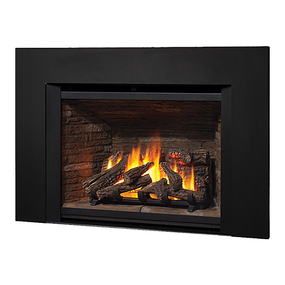
Valor Legend G4 Series Installation & Owner's Manual
Direct vent gas insert fireplace
780kn (natural gas) & 780kp (propane gas)
Hide thumbs
Also See for Legend G4 Series:
- Installation & owner's manual (44 pages) ,
- Installation and operating instructions manual (16 pages) ,
- Installation instructions manual (8 pages)
Table of Contents
Advertisement
INSTALLATION & OWNER'S MANUAL
Direct Vent Gas Insert Fireplace
780KN (natural gas) & 780KP (propane gas)
DANGER
!
A barrier designed to reduce the risk of burns from the hot
viewing glass is provided with this appliance and shall be
installed for the protection of children and other at-risk
individuals.
!
WARNING
FIRE OR EXPLOSION HAZARD
Failure to follow safety warnings exactly
could result in serious injury, death, or
property damage.
— Do not store or use gasoline or other
fl ammable vapors and liquids in the
vicinity of this or any other appliance.
— WHAT TO DO IF YOU SMELL GAS
▪ Do not try to light any appliance.
▪ Do not touch any electrical switch; do
not use any phone in your building.
▪ Leave the building immediately.
▪ Immediately call your gas supplier from
a neighbor's phone. Follow the gas
supplier's instructions.
▪ If you cannot reach your gas supplier,
call the fi re department.
— Installation and service must be
performed by a qualifi ed installer,
service agency or the gas supplier.
4006265-07
©2019, Miles Industries Ltd.
G4
HOT GLASS WILL
CAUSE BURNS.
DO NOT TOUCH GLASS
UNTIL COOLED.
NEVER ALLOW CHILDREN
TO TOUCH GLASS.
with
Please read this manual
BEFORE
operating this appliance.
INSTALLER
Leave this manual
with the appliance.
CONSUMER
Retain this manual
for future reference.
This manual contains instructions to install the
ENGINE ONLY. A front is also REQUIRED to
complete this installation. A barrier screen is pro-
vided with the front. Refer to the manual sup-
plied with the front for installation.
This appliance may be installed in an after-
market permanently located, manufactured
(mobile) home where not prohibited by local
codes.
This appliance is only for use with the type
of gas indicated on the rating plate. This
appliance is not convertible for use with
other gases, unless a certifi ed kit is used.
This appliance is a domestic room-heating
appliance. It must not be used for any other
purposes such as drying clothes, etc.
This appliance is suitable for installation in
a bedroom or bed sitting room.
Ce guide est disponible en français sur demande.
Canadian Patent 2717779
US and other patents
pending
installing and
Advertisement
Table of Contents

Related Manuals for Valor Legend G4 Series


Summary of Contents for Valor Legend G4 Series
- Page 1 INSTALLATION & OWNER’S MANUAL with Direct Vent Gas Insert Fireplace Canadian Patent 2717779 US and other patents 780KN (natural gas) & 780KP (propane gas) pending DANGER Please read this manual BEFORE installing and operating this appliance. HOT GLASS WILL CAUSE BURNS. INSTALLER DO NOT TOUCH GLASS Leave this manual...
-
Page 2: Table Of Contents
fi tter in the State assumes no responsibility for any consequential of Massachusetts. damage(s). Designed and Manufactured by / for Miles Industries Ltd. 190–2255 Dollarton Highway, North Vancouver, BC, CANADA V7H 3B1 Tel. 604-984-3496 Fax 604-984-0246 www.valorfi replaces.com... -
Page 3: Safety And Your Fireplace
Safety and Your Fireplace SAFETY AND YOUR FIREPLACE Read and understand all instructions carefully before Do not use this heater as a temporary source of starting the installation. Failure to follow these instal- heat during construction. lation instructions may result in possible fi re hazard and Due to the high temperature, the appliance should be will void the warranty. - Page 4 Safety and Your Fireplace Read and carefully follow all safety warnings and operating instructions contained in your owner’s manual Replacement manuals are available by contacting the Valor Service Department at 1-800-468-2567 or visit www.valorfi replaces.com. FOLLOW THESE IMPORTANT CHILD SAFETY...
- Page 5 SAFETY AND YOUR FIREPLACE This manual and particularly the preceeding and following pages contain very important information regarding before operating your the safe operation of your fi replace as well as maintenance instructions. Read carefully fi replace and pay special attention to the safety warnings. A heating gas appliance does require safe handling.
-
Page 6: Introduction
Each Valor fi replace curing compounds used in the manufacture of the is fully tested during the production process for your appliance. -
Page 7: Operating Your Fireplace
OWNER’S Operating Your Fireplace INFORMATION Fireplace Control Devices If the fl ames are on, they go down and you hear the valve motor wind down. You hear a clunk and a beep There are three ways to control your fi replace. indicating that the valve has received the signal from 1. -
Page 8: Using The Remote Control
OWNER’S Using the Remote Control INFORMATION Radio Frequency Turn Fireplace ON 315 MHz for USA and Canada. Press buttons until you hear a short beep; release buttons. This device complies with Part 15 of the FCC Rules and with Industry Canada license-exempt RSS standard(s). Beeps continue until pilot is lit. - Page 9 OWNER’S Using the Remote Control INFORMATION Setting ºC/24-hr or ºF/12-hr Manual Mode M A N clock Manual ame height adjustment. In MAN mode, press buttons Daytime Temperature Mode until temperature / clock display TEMP changes from When pilot is lit, room temperature is measured and compared to set °F / 12-hour °C / 24-hour...
- Page 10 OWNER’S Using the Remote Control INFORMATION Circulating Fan Operation Setting Program Timers (if equipped) You can program two periods of time between 12 am Circulating fan has 4 speed levels from and 11:50 pm in each 24-hour cycle. low to high (1 to 4 bars). Programs P1 and P2 must be set in the following order Press SET to scroll to .
- Page 11 OWNER’S Using the Remote Control INFORMATION Setting P2 ON and OFF times. Repeat same steps as Setting P1 ON and OFF times. When all settings are complete, press to save them. Timer Programming Example (default temperatures shown) 6:00 am 8:00 am 4:00 pm 10:00 pm 6:00 am...
-
Page 12: Kits & Accessories
Refl ective glass panels Risers (2-1/2”) for 790/1/2/8 788FBLV2 Fluted black panels 794BPB Backing Plates Black for 790, 791, 792 & 794BPB-1 789VRLV2 Valor Red brick panels 795CFKV2 Circulating Fan Kit Barrier Front & Backing Plates (choose one) 796ALP Adjustable Leveling Platform Screen... -
Page 13: Lighting Instructions
OWNER’S Lighting Instructions INFORMATION FOR YOUR SAFETY, READ BEFORE LIGHTING WARNING : If you do not follow these instructions exactly causing property damage, personal injury or loss of life. . To save gas, turn the pilot off when not using the appliance for a prolonged period of time. WHAT TO DO IF r’s phone. -
Page 14: Servicing & Maintenance
OWNER’S Servicing & Maintenance INFORMATION Servicing Your Fireplace We recommend having your fi replace serviced every year. Contact your supplier quoting the model number. It will be helpful if the appliance’s serial number can also be quoted. These numbers are on the information card. -
Page 15: Cleaning Your Fireplace
OWNER’S Servicing & Maintenance INFORMATION Cleaning Your Fireplace Clean the window panes following the guidelines in this section. WARNING Clean the steel trim with mild soap and warm water. DO NOT TOUCH THE GLASS WHILE IT IS HOT! Any alcohol/solvent base cleaner will weaken the coat- Let the fi... - Page 16 fi replace, damage components, cause overheating resulting in dangerous conditions. Safety warning plate Damage caused by incorrect window installa- tion is not covered by the Valor warranty. 1. Place the window in its bottom Window railing and push its top against frame 6.
-
Page 17: Checking Pilot And Burner Flames
OWNER’S Servicing & Maintenance INFORMATION Checking Pilot and Burner Flames The appliance area must always be kept clear and free from combustible materials, gasoline and other A periodic check of the pilot and burner fl ames should fl ammable vapors and liquids. be made. -
Page 18: Replacing Batteries
OWNER’S Servicing & Maintenance INFORMATION Replacing Batteries 2. Disconnect the battery holder. WARNING DO NOT ATTEMPT TO CHANGE THE BATTER- IES WHILE THE FIREPLACE IS STILL HOT! Let the fi replace cool fi rst before touching it. CAUTION DO NOT USE a screwdriver or other metallic object to remove the batteries from the battery holder or the handset! This could cause a short circuit to the receiver. -
Page 19: Specifi Cations
QUALIFIED Specifi cations INSTALLER Approval & Codes Supply Gas This appliance is certifi ed to ANSI Z21.88-2017 / CSA Heater engine 780KN is used with natural gas. 2.33-2017 American National Standard / CSA Standard Heater engine 780KP is used with propane gas. for Vented Gas Fireplace Heaters for use in Canada The supply pressure must be between the limits shown and USA, and to CGA 2.17-91 High Altitude Standard... -
Page 20: Overview
QUALIFIED Overview INSTALLER This appliance may ONLY be installed in an existing unaltered, functioning solid-fuel burning fi replace with a working fl ue and constructed of non-combustible material. DO NOT install into combustible construction. This appliance is NOT APPROVED for installation with a zero clearance kit. WARNING WARNING Some materials or items, although... -
Page 21: Dimensions
QUALIFIED Dimensions INSTALLER 33” (838 mm) 24” (610 mm) 3” 6’ (1.9 m) Fan power cord (76 mm) Optional fan 3” 3” 15” (76 mm) (76 mm) (381 mm) 15” 4” Trim (381 mm) (102 mm) (sold separately) 9-1/2” (241 mm) Gas line approx. -
Page 22: Clearances
QUALIFIED Clearances INSTALLER WARNING WARNING Some materials or items, although safe, may discolor, shrink, warp, crack, peel, and so on because of the heat produced by the fi replace. Avoid placing candles, paintings, photos, and other items sensitive to heat around the fi replace. Combustible Mantel Clearances Mantel Pro- 1”... -
Page 23: Venting
QUALIFIED Venting INSTALLER Typical Vent Installation See list of approved Venting Accessories on page 41 of this manual. NOTE: Flexible co-linear vent pipes may only be installed into existing non-combustible solid-fuel burning fi replaces and chimneys. Terminal Cap Vent Location The vent terminal must be located through the roof. -
Page 24: Existing Fireplace Preparation
QUALIFIED Installation Planning INSTALLER Only qualifi ed licensed or trained personnel should install this appliance. Installer—READ THIS FIRST 1. YOU NEED TO KNOW FROM THE 13. Refi t window. HOMEOWNER what accessories (surround, 14. Reinstall the hot glass warning plate if it has been screen, fan/blower, etc.) will be installed with removed. -
Page 25: Installation
QUALIFIED Existing Fireplace Preparation INSTALLER Gas Line Routing Combustible Mantels Plan the routing of the gas line before proceeding. Combustible mantel clearances must conform to those Utilize the existing hole for the gas line of the factory- required for the original solid-fuel fi replace into which built fi... -
Page 26: Remove Window
QUALIFIED Installation INSTALLER Remove Window The window is held in place by a spring-loaded lever on each side. 1. To remove the window, locate the levers on each side of the window towards the top. Using your fi nger, pull the lever towards you and unhook it from the window frame bracket. -
Page 27: Connect Venting
QUALIFIED Installation INSTALLER Connect Venting IMPORTANT: This appliance’s venting system is room sealed and therefore, does not require room air to be used in the combustion process. 1. Rough-in two 3” diameter vent liners into the existing chimney system from the roof. Be careful not to tear or damage the liners in the process. -
Page 28: Connect Gas Supply
QUALIFIED Installation INSTALLER Connect Gas Supply Pressure Test Points The gas supply inlet connection is a 1/2” NPT female. The minimum supply pressure is given in the Gas shut-off valve supplied on the end of stainless section Specifi cations of this manual—page 19. steel fl... - Page 29 QUALIFIED Installation INSTALLER Alternate Inlet Connection Use common elbow and fi ttings (not supplied) to redirect the position of In cases where local codes do not permit the fl ex the fl ex connector. NOTE: the fl ex connector to be used inside the appliance case, connector bend radius must be no reconnect the fl...
-
Page 30: Install Liner Panels
QUALIFIED Installation INSTALLER Install Liner Panels 5. Rotate the anchor up and out of the way and slide the left hand side panel against the fi rebox side. The following guidelines apply to all panels except Rotate the anchor back down to hold the panel. 787RGL Refl... -
Page 31: Install Traditional Logs 782Lsk
QUALIFIED Installation INSTALLER 9. Reinstall the front brick support. 11. With logs only: Install the front bricks in front of the burner. 10. Reinstall the rear log support (3 screws). Its rear 12. With logs only: Slide the cast iron grate in the edge rests on the rear brick support ledge. - Page 32 QUALIFIED Installation INSTALLER 2. Place the black glass piece, smooth side up, on 4. Place the right front log with its left end fl at on the top of the burner and move it forward to rest in the glass. The notch in the log should place squarely on grooved recess of the grate and center it.
- Page 33 QUALIFIED Installation INSTALLER 6. Identify the top right log. It is the longest of the two 7. Place the top left log’s wider end on the peg of the remaining logs. Place its wider end on the front right front left log and rest its narrow end in the notch on log’s peg and rest its narrow end in the notch on the the rear log.
-
Page 34: Install Ceramic Rocks 781Rsk
QUALIFIED Installation INSTALLER Install Ceramic Rocks 781RSK Unpack the ceramic rocks very carefully to avoid damaging them. Install the rocks as shown. Please note that the position of some of the rocks identifi ed in the following instructions is critical to ensure proper performance of the appliance. - Page 35 QUALIFIED Installation INSTALLER 4. Each rock is embossed 8. Identify the rocks 7, 9, 11 and 14. These rocks underneath with a number have one hole underneath and fi t on the peg of and an arrow indicating the rocks 6, 8, 10 and 13 respectively. Install these its position.
-
Page 36: Refi T And Check Window
Damage caused by incorrect window installa- tion is not covered by the Valor warranty. 5. If the Hot Glass Warning plate has been removed from the front lower corner of the window, reinstall it by sliding it between the glass and the frame as indicated below. -
Page 37: Synchronize Remote Control
QUALIFIED Installation INSTALLER Synchronize Remote Control 3. With a sharp object, press and hold the receiver’s reset button until you hear one short and one long The receiver and the handset of the remote control beep. Release the reset button after the second system must be initially synchronized before the fi... -
Page 38: Check Operation
QUALIFIED Installation INSTALLER Check Operation Depending of fuel bed used, altitude and other considerations, the fl ame picture may be improved by Turn the fi replace fl ame up and down using the adjusting the aeration. The need for adjustment should remote control to confi... -
Page 39: Install Front, Trim And Barrier Screen
QUALIFIED Installation INSTALLER Install Front, Trim and Barrier Screen Install the front or trim chosen by the customer for their fi replace. Install as well the barrier screen which is provided with the front or trim. Show the customer how to access the controls when the front or trim are installed and how to remove them. -
Page 40: Wiring Diagram
QUALIFIED Wiring Diagram INSTALLER Optional Wall Switch Kit 1265WSK Connector Yellow Optional 795CFKV2 Control Module Battery Holder 4 AA Batteries GV60 MAX Wiring Diagram... -
Page 41: Approved Venting Components
QUALIFIED Approved Venting Components INSTALLER... -
Page 42: Warranty
Installation and maintenance must be performed by 5. No Other Warranty an authorized and trained dealer in accordance with All obligations to repair this unit are de ned in this warranty. -
Page 43: Spare Parts
OWNER’S Spare Parts INFORMATION Part Part Description Description Number Number AutoFire exhaust slide assembly 4006540 Ignition cable 4001039 Exhaust slide gasket 4001662 Ignition cable sleeve 4002244 Valve access cover 4002289 Switch with cable 4001036 Access panel gasket 4002664 Cable interrupter 4001035 Access plate 4002510... - Page 44 Ledgestone 4002477 Ceramic platform—sand 4002439 Ceramic black 4002481 Platform support assembly 4002663 Ceramic black 4002481 Liner panels—complete set Valor red brick 4002484 Ledgestone 786LSLV2 GV60 Valve repair kit 4004544 Refl ective glass 787RGL Ceramic black 788FBLV2 Valor red brick 789VRLV2...
- Page 45 OWNER’S Spare Parts INFORMATION 51 - 52 782LSK 54 53 55 Natural gas 66 67 22 - 26 Propane gas 11 - 17 781RSK 39 38...
- Page 47 Thank You ... For purchasing a Valor by Miles Industries. Your new radiant gas heater is a technical appliance that must be installed by a qualifi ed installer. Please fi ll in the information below. The information provided will be used for customer records only.
- Page 48 Tape Shut Fold here Postage needed Valor Fireplaces 190 - 2255 Dollarton Highway North Vancouver, BC V7H 3B1 Canada Online Warranty registration at www.valorfi replaces.com Thank you for choosing a Valor Product...
Need help?
Do you have a question about the Legend G4 Series and is the answer not in the manual?
Questions and answers